

TRL-DLS User Manual
Page 2
... BEEN ADVISED OF THE POSSIBILITY OF SUCH DAMAGES ARISING FROM ANY DEFECT OR ERROR IN THIS MANUAL OR PRODUCT. Product Name: ASUS TRL-DLS Manual Revision: 1.03 E979 Release Date: May 2002 2 ASUS TRL-DLS User's Manual SPECIFICATIONS AND INFORMATION CONTAINED IN THIS MANUAL ARE FURNISHED FOR INFORMATIONAL USE ONLY, AND ARE SUBJECT TO CHANGE AT...
... BEEN ADVISED OF THE POSSIBILITY OF SUCH DAMAGES ARISING FROM ANY DEFECT OR ERROR IN THIS MANUAL OR PRODUCT. Product Name: ASUS TRL-DLS Manual Revision: 1.03 E979 Release Date: May 2002 2 ASUS TRL-DLS User's Manual SPECIFICATIONS AND INFORMATION CONTAINED IN THIS MANUAL ARE FURNISHED FOR INFORMATIONAL USE ONLY, AND ARE SUBJECT TO CHANGE AT...
TRL-DLS User Manual
Page 3
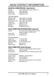
... Road, Peitou, Taipei, Taiwan 112 General Tel: +886-2-2894-3447 General Fax: +886-2-2894-3449 General Email: info@asus.com.tw Technical Support MB/Others (Tel): +886-2-2890-7121 (English) Notebook (Tel): +886-2-2890-7122 (English) ...): +886-2-2890-7123 (English) Support Fax: +886-2-2890-7698 Support Email: tsd@asus.com.tw Web Site: www.asus.com.tw Newsgroup: cscnews.asus.com.tw ASUS COMPUTER INTERNATIONAL (America) Address: 6737 Mowry Avenue, Mowry Business Center, Building 2, Newark,...de/support (for online support) Web Site: www.asuscom.de ASUS TRL-DLS User's Manual 3
... Road, Peitou, Taipei, Taiwan 112 General Tel: +886-2-2894-3447 General Fax: +886-2-2894-3449 General Email: info@asus.com.tw Technical Support MB/Others (Tel): +886-2-2890-7121 (English) Notebook (Tel): +886-2-2890-7122 (English) ...): +886-2-2890-7123 (English) Support Fax: +886-2-2890-7698 Support Email: tsd@asus.com.tw Web Site: www.asus.com.tw Newsgroup: cscnews.asus.com.tw ASUS COMPUTER INTERNATIONAL (America) Address: 6737 Mowry Avenue, Mowry Business Center, Building 2, Newark,...de/support (for online support) Web Site: www.asuscom.de ASUS TRL-DLS User's Manual 3
TRL-DLS User Manual
Page 4
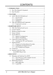
... the Computer System 35 4.1.2 Updating BIOS Procedures 37 4.2 BIOS Setup Program 39 4.2.1 BIOS Menu Bar 40 4.2.2 Legend Bar 40 4 ASUS TRL-DLS User's Manual INTRODUCTION 7 1.1 How This Manual Is Organized 7 1.2 Item Checklist 7 2. HARDWARE SETUP 14 3.1 TRL-DLS Motherboard Layout 14 3.2 Layout Contents 15 3.3 Hardware Setup Procedure 16 3.4 Jumper Settings 16 3.5 System Memory 17 3.5.1 Memory Configurations...
... the Computer System 35 4.1.2 Updating BIOS Procedures 37 4.2 BIOS Setup Program 39 4.2.1 BIOS Menu Bar 40 4.2.2 Legend Bar 40 4 ASUS TRL-DLS User's Manual INTRODUCTION 7 1.1 How This Manual Is Organized 7 1.2 Item Checklist 7 2. HARDWARE SETUP 14 3.1 TRL-DLS Motherboard Layout 14 3.2 Layout Contents 15 3.3 Hardware Setup Procedure 16 3.4 Jumper Settings 16 3.5 System Memory 17 3.5.1 Memory Configurations...
TRL-DLS User Manual
Page 5
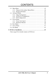
CONTENTS 4.3 Main Menu 42 4.3.1 Primary & Secondary Master/Slave 44 4.3.2 Keyboard Features 47 4.4 Advanced Menu 48 4.4.1 Chip Configuration 50 4.4.2 I/O Device Configuration 51 4.4.3 PCI Configuration 52 4.5 Power Menu 54 4.5.1 Power Up Control 56 4.5.2 Hardware Monitor 58 4.6 Boot Menu 59 4.7 Server Menu 61 4.8 Exit Menu 62 5. OS Driver Installation 65 (Turn to page 66 for detailed contents on OS Drivers) ASUS TRL-DLS User's Manual 5
CONTENTS 4.3 Main Menu 42 4.3.1 Primary & Secondary Master/Slave 44 4.3.2 Keyboard Features 47 4.4 Advanced Menu 48 4.4.1 Chip Configuration 50 4.4.2 I/O Device Configuration 51 4.4.3 PCI Configuration 52 4.5 Power Menu 54 4.5.1 Power Up Control 56 4.5.2 Hardware Monitor 58 4.6 Boot Menu 59 4.7 Server Menu 61 4.8 Exit Menu 62 5. OS Driver Installation 65 (Turn to page 66 for detailed contents on OS Drivers) ASUS TRL-DLS User's Manual 5

TRL-DLS User Manual
Page 6
... complies with manufacturer's instructions, may cause undesired operation. Cet appareil numérique de la classe B est conforme à la norme NMB-003 du Canada. 6 ASUS TRL-DLS User's Manual However, there is connected. • Consult the dealer or an experienced radio/TV technician for help. These limits are designed to this equipment...
... complies with manufacturer's instructions, may cause undesired operation. Cet appareil numérique de la classe B est conforme à la norme NMB-003 du Canada. 6 ASUS TRL-DLS User's Manual However, there is connected. • Consult the dealer or an experienced radio/TV technician for help. These limits are designed to this equipment...
TRL-DLS User Manual
Page 7
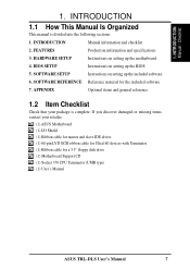
... material for a 3.5" floppy disk drive (1) Motherboard Support CD (1) Socket 370 CPU Terminator (UMB type) (1) User's Manual ASUS TRL-DLS User's Manual 7 BIOS SETUP Instructions on setting up the included software 6. INTRODUCTION Manual information and checklist 2. SOFTWARE SETUP Instructions on... setting up the motherboard. 4. APPENDIX Optional items and general reference 1.2 Item Checklist Check that your retailer. (1) ASUS Motherboard (1) I/O Shield (1) Ribbon cable for master and slave IDE drives (1) 68-pin LVD SCSI ribbon cable for Ultra160 ...
... material for a 3.5" floppy disk drive (1) Motherboard Support CD (1) Socket 370 CPU Terminator (UMB type) (1) User's Manual ASUS TRL-DLS User's Manual 7 BIOS SETUP Instructions on setting up the included software 6. INTRODUCTION Manual information and checklist 2. SOFTWARE SETUP Instructions on... setting up the motherboard. 4. APPENDIX Optional items and general reference 1.2 Item Checklist Check that your retailer. (1) ASUS Motherboard (1) I/O Shield (1) Ribbon cable for master and slave IDE drives (1) 68-pin LVD SCSI ribbon cable for Ultra160 ...
TRL-DLS User Manual
Page 8
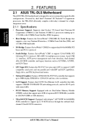
FEATURES 2.1 ASUS TRL-DLS Motherboard The ASUS TRL-DLS motherboard is designed for 1280x1024 and true color resolutions. • LAN Support:...(DIMM) sockets that require flexible configurations. Powered by dual Intel® Pentium® III Tualatin™ /Coppermine processors, the TRL-DLS efficiently complies with today's demand for a highintegration server. 2.1.1 Specifications • Processor Support: Supports dual Socket 370-based Intel ... up to 30 SCSI devices through the onboard dualchannel Ultra160 SCSI connectors. 8 ASUS TRL-DLS User's Manual 2. FEATURES Specifications 2.
FEATURES 2.1 ASUS TRL-DLS Motherboard The ASUS TRL-DLS motherboard is designed for 1280x1024 and true color resolutions. • LAN Support:...(DIMM) sockets that require flexible configurations. Powered by dual Intel® Pentium® III Tualatin™ /Coppermine processors, the TRL-DLS efficiently complies with today's demand for a highintegration server. 2.1.1 Specifications • Processor Support: Supports dual Socket 370-based Intel ... up to 30 SCSI devices through the onboard dualchannel Ultra160 SCSI connectors. 8 ASUS TRL-DLS User's Manual 2. FEATURES Specifications 2.

TRL-DLS User Manual
Page 9
...Management Bus interface, which provides more control and protection over the motherboard. ASUS TRL-DLS User's Manual 9 2. The onboard battery supports detection even when normal power is removed and through the onboard hardware ASUS ASIC. • Enhanced ACPI: Programmable BIOS (Flash EEPROM), offering enhanced... EMRL (Embedded RAID Logic). • USB Ports: Two stacked USB connectors to provide for a separate IOAPIC chip. • ASUS Server Management Card: The optional ASMC-LE, ASMC-ME, and ASMC-HE cards support Intelligent Platform Management Interface (IPMI), system health...
...Management Bus interface, which provides more control and protection over the motherboard. ASUS TRL-DLS User's Manual 9 2. The onboard battery supports detection even when normal power is removed and through the onboard hardware ASUS ASIC. • Enhanced ACPI: Programmable BIOS (Flash EEPROM), offering enhanced... EMRL (Embedded RAID Logic). • USB Ports: Two stacked USB connectors to provide for a separate IOAPIC chip. • ASUS Server Management Card: The optional ASMC-LE, ASMC-ME, and ASMC-HE cards support Intelligent Platform Management Interface (IPMI), system health...
TRL-DLS User Manual
Page 10
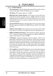
...NT/2000/XP. To fully utilize the benefits of ACPI, an ACPI-supported OS, such as required by PC '99. 10 ASUS TRL-DLS User's Manual FEATURES Performance 2. Ultra160 is also implemented on the following high-level goals: support for Plug and Play compatibility and...certification. Color-coded connectors and descriptive icons make identification easy as Windows 2000, must be ready around the clock, yet satisfy all ASUS smart series motherboards. FEATURES 2.1.2 Performance • Ultra Performance: Onboard Ultra160 dual channel SCSI controller with slower SCSI devices so that...
...NT/2000/XP. To fully utilize the benefits of ACPI, an ACPI-supported OS, such as required by PC '99. 10 ASUS TRL-DLS User's Manual FEATURES Performance 2. Ultra160 is also implemented on the following high-level goals: support for Plug and Play compatibility and...certification. Color-coded connectors and descriptive icons make identification easy as Windows 2000, must be ready around the clock, yet satisfy all ASUS smart series motherboards. FEATURES 2.1.2 Performance • Ultra Performance: Onboard Ultra160 dual channel SCSI controller with slower SCSI devices so that...
TRL-DLS User Manual
Page 11
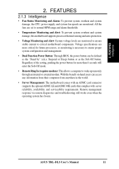
.... • Temperature Monitoring and Alert: To prevent system overheat and system damage, this benefit on-hand, users can be defined as the Soft-Off button. ASUS TRL-DLS User's Manual 11 2. Remote management response via remote diagnostics and troubleshooting still works even when the operating system has frozen. Suspend or Sleep) button or...
.... • Temperature Monitoring and Alert: To prevent system overheat and system damage, this benefit on-hand, users can be defined as the Soft-Off button. ASUS TRL-DLS User's Manual 11 2. Remote management response via remote diagnostics and troubleshooting still works even when the operating system has frozen. Suspend or Sleep) button or...
TRL-DLS User Manual
Page 12
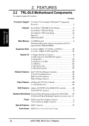
FEATURES 2.2 TRL-DLS Motherboard Components See opposite page for Pentium® III Tualatin™ /Coppermine Processors 3 Chipsets ServerWorks® CNB20HE-SL Host Bridge 4 ServerWorks® CIOB2 I/O Bridge 13 ... 24-pin Power Supply Connector 2 +12V 8-pin Power Supply Connector 5 Special Features eRMC Connector 17 Form Factor EATX 12 in . (30.5 cm x 33 cm) 12 ASUS TRL-DLS User's Manual Location Processor Support (2) Socket 370 for locations. x 13 in . 2. FEATURES MB Components 2.
FEATURES 2.2 TRL-DLS Motherboard Components See opposite page for Pentium® III Tualatin™ /Coppermine Processors 3 Chipsets ServerWorks® CNB20HE-SL Host Bridge 4 ServerWorks® CIOB2 I/O Bridge 13 ... 24-pin Power Supply Connector 2 +12V 8-pin Power Supply Connector 5 Special Features eRMC Connector 17 Form Factor EATX 12 in . (30.5 cm x 33 cm) 12 ASUS TRL-DLS User's Manual Location Processor Support (2) Socket 370 for locations. x 13 in . 2. FEATURES MB Components 2.
TRL-DLS User Manual
Page 14
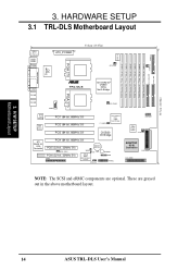
... PS/2 T: Mouse B: Keyboard USB1 USB2 COM1 ATX_POWER 33.2cm (13.07in) CPUFAN1 PARALLEL PORT Super I/O PGA 370 VGA RJ-45 ® TRL-DLS ServerWorks® CNB20 HESL North Bridge PGA 370 RJ-45 COM2 CPUFAN2 Intel Fast Ethernet Intel Fast Ethernet PCI1 (64-bit, 66MHz 3V) PCI2 (... WOR R216 ASUS ASIC with Hardware Monitor CHASSIS BUZZER SMB PANEL USBPORT 4Mbit Flash BIOS SYSFAN1 ADAPTEC SCSI Controller CHB-WIDE CHA-WIDE 34 1 68 35 NOTE: The SCSI and eRMC components are grayed out in the above motherboard layout. 3. H/W SETUP Motherboard Layout 14 ASUS TRL-DLS User's Manual...
... PS/2 T: Mouse B: Keyboard USB1 USB2 COM1 ATX_POWER 33.2cm (13.07in) CPUFAN1 PARALLEL PORT Super I/O PGA 370 VGA RJ-45 ® TRL-DLS ServerWorks® CNB20 HESL North Bridge PGA 370 RJ-45 COM2 CPUFAN2 Intel Fast Ethernet Intel Fast Ethernet PCI1 (64-bit, 66MHz 3V) PCI2 (... WOR R216 ASUS ASIC with Hardware Monitor CHASSIS BUZZER SMB PANEL USBPORT 4Mbit Flash BIOS SYSFAN1 ADAPTEC SCSI Controller CHB-WIDE CHA-WIDE 34 1 68 35 NOTE: The SCSI and eRMC components are grayed out in the above motherboard layout. 3. H/W SETUP Motherboard Layout 14 ASUS TRL-DLS User's Manual...
TRL-DLS User Manual
Page 15
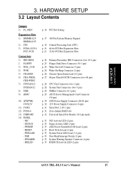
...-pin Ultra160 SCSI Connectors (two 68-pin) p. 28 CPU Fan Connectors (two 3-pin) p. 28 System Fan Connectors (two 3-pin) p. 29 SMBus Connector (6-1 pins) p. 29 ASUS Server Management Card Connector (50-pin) p. 30 ATX Power Supply Connector (20/24-pin) p. 30 12V Power Supply Connector (8-pin) p. 31 Serial Port 2 (10-1 pin...pin) p. 33 System Power LED Lead (3-1 pin) p. 33 Non-Mask Interrupt Switch (2-pin) p. 33 System Warning Speaker Connector (4-pin) p. 33 IDE/SCSI Activity LED (2-pin) ASUS TRL-DLS User's Manual 15 NIC - H/W SETUP Layout Contents 3. PWRSW - PWR.LED - NMI - 3.
...-pin Ultra160 SCSI Connectors (two 68-pin) p. 28 CPU Fan Connectors (two 3-pin) p. 28 System Fan Connectors (two 3-pin) p. 29 SMBus Connector (6-1 pins) p. 29 ASUS Server Management Card Connector (50-pin) p. 30 ATX Power Supply Connector (20/24-pin) p. 30 12V Power Supply Connector (8-pin) p. 31 Serial Port 2 (10-1 pin...pin) p. 33 System Power LED Lead (3-1 pin) p. 33 Non-Mask Interrupt Switch (2-pin) p. 33 System Warning Speaker Connector (4-pin) p. 33 IDE/SCSI Activity LED (2-pin) ASUS TRL-DLS User's Manual 15 NIC - H/W SETUP Layout Contents 3. PWRSW - PWR.LED - NMI - 3.

TRL-DLS User Manual
Page 16
... grounded object, such as the power supply case, before you install or remove any internal component. 2. H/W SETUP Jumper ® TRL-DLS TRL-DLS PCI Slot Setting P1_66EN 12 23 Normal (Default) Force 33Mhz 16 ASUS TRL-DLS User's Manual Install the Central Processing Unit (CPU) 4. 3. Unplug the power cord from the power supply. Failure to do not...
... grounded object, such as the power supply case, before you install or remove any internal component. 2. H/W SETUP Jumper ® TRL-DLS TRL-DLS PCI Slot Setting P1_66EN 12 23 Normal (Default) Force 33Mhz 16 ASUS TRL-DLS User's Manual Install the Central Processing Unit (CPU) 4. 3. Unplug the power cord from the power supply. Failure to do not...
TRL-DLS User Manual
Page 17
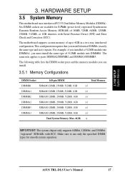
... PC133 Dual Inline Memory Modules (DIMMs). This configuration requires that you install identical DIMMs (exactly the same type and size) in a two-way interleaved configuration. ASUS TRL-DLS User's Manual 17
... PC133 Dual Inline Memory Modules (DIMMs). This configuration requires that you install identical DIMMs (exactly the same type and size) in a two-way interleaved configuration. ASUS TRL-DLS User's Manual 17
TRL-DLS User Manual
Page 18
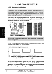
SDRAM DIMMs have different pin contacts on each side. ® TRL-DLS TRL-DLS 168-Pin DIMM Sockets IMPORTANT: Always install DIMMs in one direction. H/W SETUP System Memory The notches on the DIMMs (see 3.3 Hardware Setup Procedure for the ... that you unplug the power supply when adding or removing memory modules or other system components. This motherboard supports four clock signals per DIMM. 18 ASUS TRL-DLS User's Manual Because the number of pins are different on the motherboard. Failure to do so may cause severe damage to prevent the wrong type...
SDRAM DIMMs have different pin contacts on each side. ® TRL-DLS TRL-DLS 168-Pin DIMM Sockets IMPORTANT: Always install DIMMs in one direction. H/W SETUP System Memory The notches on the DIMMs (see 3.3 Hardware Setup Procedure for the ... that you unplug the power supply when adding or removing memory modules or other system components. This motherboard supports four clock signals per DIMM. 18 ASUS TRL-DLS User's Manual Because the number of pins are different on the motherboard. Failure to do so may cause severe damage to prevent the wrong type...
TRL-DLS User Manual
Page 19
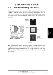
... CPU is important that you to 1.53+GHz with 133MHz Front Side Bus (FSB). H/W SETUP CPU ASUS TRL-DLS User's Manual 19 Pentium III (Coppermine) FC-PGA ® TRL-DLS Gold Arrow Pentium III (Tualatin) FC-PGA2 Gold Arrow TRL-DLS Socket 370 Socket 370 Terminator (Use when only one corner) to help you identify the proper...
... CPU is important that you to 1.53+GHz with 133MHz Front Side Bus (FSB). H/W SETUP CPU ASUS TRL-DLS User's Manual 19 Pentium III (Coppermine) FC-PGA ® TRL-DLS Gold Arrow Pentium III (Tualatin) FC-PGA2 Gold Arrow TRL-DLS Socket 370 Socket 370 Terminator (Use when only one corner) to help you identify the proper...

TRL-DLS User Manual
Page 20
... in place, press it fits in one orientation. The figure on the socket while you would install a CPU. CAUTION! It will damage the motherboard! 20 ASUS TRL-DLS User's Manual H/W SETUP CPU Installation 3. HARDWARE SETUP 3.6.1 Installing the CPU and Terminator Follow these steps to a 90°-100° angle. 3. Carefully insert the CPU...
... in place, press it fits in one orientation. The figure on the socket while you would install a CPU. CAUTION! It will damage the motherboard! 20 ASUS TRL-DLS User's Manual H/W SETUP CPU Installation 3. HARDWARE SETUP 3.6.1 Installing the CPU and Terminator Follow these steps to a 90°-100° angle. 3. Carefully insert the CPU...
TRL-DLS User Manual
Page 21
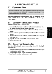
... that you intend to both your motherboard is completely seated on the system and change the necessary BIOS settings, if any. Refer to the card. ASUS TRL-DLS User's Manual 21 H/W SETUP Expansion Cards 3. Failure to do so may need to install an expansion card. 1. Align the card connector with the screw you...
... that you intend to both your motherboard is completely seated on the system and change the necessary BIOS settings, if any. Refer to the card. ASUS TRL-DLS User's Manual 21 H/W SETUP Expansion Cards 3. Failure to do so may need to install an expansion card. 1. Align the card connector with the screw you...
TRL-DLS User Manual
Page 22
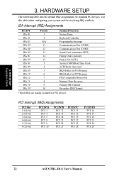
... 19 PCI 22 PCI 25 PCI 28 PCI INTD PCI 14 PCI 17 PCI 20 PCI 23 PCI 26 PCI 29 3. H/W SETUP Expansion Cards 22 ASUS TRL-DLS User's Manual HARDWARE SETUP The following table lists the default IRQ assignments for resolving IRQ conflicts. ISA Interrupt (IRQ) Assignments ISA INT ISA 00 ISA...
... 19 PCI 22 PCI 25 PCI 28 PCI INTD PCI 14 PCI 17 PCI 20 PCI 23 PCI 26 PCI 29 3. H/W SETUP Expansion Cards 22 ASUS TRL-DLS User's Manual HARDWARE SETUP The following table lists the default IRQ assignments for resolving IRQ conflicts. ISA Interrupt (IRQ) Assignments ISA INT ISA 00 ISA...


