
TR-DLS User Manual
Page 2
... THE PRODUCTS AND SOFTWARE DESCRIBED IN IT. Copyright © 2000 ASUSTeK COMPUTER INC. Product Name: ASUS TR-DLS Manual Revision: 3.00 E887 Release Date: November 2001 2 ASUS TR-DLS User's Manual ASUS PROVIDES THIS MANUAL "AS IS" WITHOUT WARRANTY OF ANY KIND, EITHER EXPRESS OR IMPLIED, INCLUDING BUT...means indicated on the product itself. For previous or updated manuals, BIOS, drivers, or product release information, contact ASUS at http://www.asus.com.tw or through any means, except documentation kept by ASUS; The product name and revision number are both printed on the ...
... THE PRODUCTS AND SOFTWARE DESCRIBED IN IT. Copyright © 2000 ASUSTeK COMPUTER INC. Product Name: ASUS TR-DLS Manual Revision: 3.00 E887 Release Date: November 2001 2 ASUS TR-DLS User's Manual ASUS PROVIDES THIS MANUAL "AS IS" WITHOUT WARRANTY OF ANY KIND, EITHER EXPRESS OR IMPLIED, INCLUDING BUT...means indicated on the product itself. For previous or updated manuals, BIOS, drivers, or product release information, contact ASUS at http://www.asus.com.tw or through any means, except documentation kept by ASUS; The product name and revision number are both printed on the ...

TR-DLS User Manual
Page 4
... 7 1.2 Item Checklist 7 2. FEATURES 8 2.1 ASUS TR-DLS Motherboard 8 2.1.1 Specifications 8 2.1.2 Performance 10 2.1.3 Intelligence 11 2.2 TR-DLS Motherboard Components 12 2.2.1 Component Locations 13 3. BIOS SETUP 41 4.1 Managing and Updating Your BIOS 41 4.1.1 Upon First Use of the Computer System 41 4.1.2 Updating BIOS Procedures 43 4.2 BIOS Setup Program 45 4.2.1 BIOS Menu Bar 46 4.2.2 Legend Bar 46 4 ASUS TR-DLS User's Manual HARDWARE SETUP 14 3.1 TR-DLS Motherboard Layout 14...
... 7 1.2 Item Checklist 7 2. FEATURES 8 2.1 ASUS TR-DLS Motherboard 8 2.1.1 Specifications 8 2.1.2 Performance 10 2.1.3 Intelligence 11 2.2 TR-DLS Motherboard Components 12 2.2.1 Component Locations 13 3. BIOS SETUP 41 4.1 Managing and Updating Your BIOS 41 4.1.1 Upon First Use of the Computer System 41 4.1.2 Updating BIOS Procedures 43 4.2 BIOS Setup Program 45 4.2.1 BIOS Menu Bar 46 4.2.2 Legend Bar 46 4 ASUS TR-DLS User's Manual HARDWARE SETUP 14 3.1 TR-DLS Motherboard Layout 14...
TR-DLS User Manual
Page 7
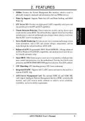
... following sections: 1. SOFTWARE REFERENCE Reference material for a 3.5" floppy disk drive (1) Support drivers and utilities (1) Socket 370 CPU Terminator (UMB type) (1) This Motherboard User's Manual ASUS TR-DLS User's Manual 7 SOFTWARE SETUP Instructions on setting up the BIOS 5. INTRODUCTION Manual information and checklist 2. APPENDIX Optional items and general reference 1.2 Item Checklist Check that your retailer...
... following sections: 1. SOFTWARE REFERENCE Reference material for a 3.5" floppy disk drive (1) Support drivers and utilities (1) Socket 370 CPU Terminator (UMB type) (1) This Motherboard User's Manual ASUS TR-DLS User's Manual 7 SOFTWARE SETUP Instructions on setting up the BIOS 5. INTRODUCTION Manual information and checklist 2. APPENDIX Optional items and general reference 1.2 Item Checklist Check that your retailer...
TR-DLS User Manual
Page 9
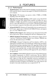
2. Provides boot block write protection, and HD/SCSI/MO/ZIP/CD/Floppy boot selection. ASUS TR-DLS User's Manual 9 FEATURES • SMBus: Features the System Management Bus interface, which provides more control and protection over the motherboard. The onboard... and one parallel port with EPP and ECP capabilities. • Chassis Intrusion Detection: Chassis intrusion circuitry can log chassis open events into the system BIOS. Year 2000 certified. • CPU Throttling: CPU throttling protects CPU from overheating. • Integrated IOAPIC: Supports full 32-APIC entries and removes...
2. Provides boot block write protection, and HD/SCSI/MO/ZIP/CD/Floppy boot selection. ASUS TR-DLS User's Manual 9 FEATURES • SMBus: Features the System Management Bus interface, which provides more control and protection over the motherboard. The onboard... and one parallel port with EPP and ECP capabilities. • Chassis Intrusion Detection: Chassis intrusion circuitry can log chassis open events into the system BIOS. Year 2000 certified. • CPU Throttling: CPU throttling protects CPU from overheating. • Integrated IOAPIC: Supports full 32-APIC entries and removes...
TR-DLS User Manual
Page 10
...can handle rates up to flat ribbon cables used . • New Compliancy: Both the BIOS and hardware levels of ACPI, an ACPI-supported OS, such as required by PC '99. 10 ASUS TR-DLS User's Manual The new SDG2.0 requirements for systems and components are not wasted. (Ultra160/...320 SCSI cables have twisted pairs compared to 160MB/s or 320MB/s. 2. Ultra160/320 is also implemented on all ASUS smart series motherboards. To fully utilize ...
...can handle rates up to flat ribbon cables used . • New Compliancy: Both the BIOS and hardware levels of ACPI, an ACPI-supported OS, such as required by PC '99. 10 ASUS TR-DLS User's Manual The new SDG2.0 requirements for systems and components are not wasted. (Ultra160/...320 SCSI cables have twisted pairs compared to 160MB/s or 320MB/s. 2. Ultra160/320 is also implemented on all ASUS smart series motherboards. To fully utilize ...
TR-DLS User Manual
Page 11
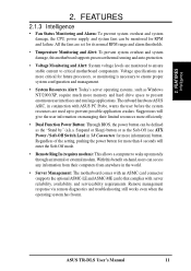
...Suspend or Sleep) button or as Windows NT/2000/XP, require much more efficiently. • Dual Function Power Button: Through BIOS, the power button can access any information from their limited resources more memory and hard drive space to ensure proper system configuration and...warns the user before the system resources are monitored to ensure stable current to prevent possible application crashes. FEATURES Intelligence 2. ASUS TR-DLS User's Manual 11 With this motherboard supports processor thermal sensing and auto-protection. • Voltage Monitoring and Alert: System...
...Suspend or Sleep) button or as Windows NT/2000/XP, require much more efficiently. • Dual Function Power Button: Through BIOS, the power button can access any information from their limited resources more memory and hard drive space to ensure proper system configuration and...warns the user before the system resources are monitored to ensure stable current to prevent possible application crashes. FEATURES Intelligence 2. ASUS TR-DLS User's Manual 11 With this motherboard supports processor thermal sensing and auto-protection. • Voltage Monitoring and Alert: System...
TR-DLS User Manual
Page 14
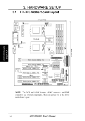
...I/O ATI CLRCMOS PCI4 (32-bit, 33MHz 5V) 4Mbit WOR Flash PCI5 (32-bit, 33MHz 5V) BIOS RAGE XL VGA Controller BPSMB ServerWorks ® RCC CSB5 South Bridge BUZZER ASUS ASIC PCI6 (32-bit, 33MHz 5V) with Hardware Monitor BPSMB Primary IDE1 Secondary IDE2 eRMC CONNECTOR IPMI ...FLOPPY PANEL HD_LED NOTE: The SCSI and ASMC features, eRMC connector, and IPMI connectors are grayed out in the above motherboard layout. 14 ASUS TR-DLS User's Manual...
...I/O ATI CLRCMOS PCI4 (32-bit, 33MHz 5V) 4Mbit WOR Flash PCI5 (32-bit, 33MHz 5V) BIOS RAGE XL VGA Controller BPSMB ServerWorks ® RCC CSB5 South Bridge BUZZER ASUS ASIC PCI6 (32-bit, 33MHz 5V) with Hardware Monitor BPSMB Primary IDE1 Secondary IDE2 eRMC CONNECTOR IPMI ...FLOPPY PANEL HD_LED NOTE: The SCSI and ASMC features, eRMC connector, and IPMI connectors are grayed out in the above motherboard layout. 14 ASUS TR-DLS User's Manual...
TR-DLS User Manual
Page 17
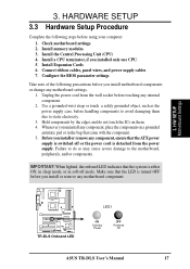
...cord from the wall socket before touching any component, ensure that theATX power supply is switched off mode. Configure the BIOS parameter settings Take note of the following steps before you install or remove any motherboard component. 3. IMPORTANT: When ... system is turned OFF before using your computer: 1. Check motherboard settings 2. H/W SETUP Motherboard Settings TR-DLS TR-DLS Onboard LED LED1 ON Standby Power OFF Powered Off ASUS TR-DLS User's Manual 17 Whenever you install motherboard components or change any component, place the components on them...
...cord from the wall socket before touching any component, ensure that theATX power supply is switched off mode. Configure the BIOS parameter settings Take note of the following steps before you install or remove any motherboard component. 3. IMPORTANT: When ... system is turned OFF before using your computer: 1. Check motherboard settings 2. H/W SETUP Motherboard Settings TR-DLS TR-DLS Onboard LED LED1 ON Standby Power OFF Powered Off ASUS TR-DLS User's Manual 17 Whenever you install motherboard components or change any component, place the components on them...

TR-DLS User Manual
Page 22
... Hold down the key during the boot process and enter BIOS setup to Clear CMOS PCI3 (32-bit, 33MHz 5V) PCI4 (32-bit, 33MHz 5V) TR-DLS Clear RTC RAM 22 ASUS TR-DLS User's Manual H/W SETUP Motherboard Settings TR-DLS KBPWR 2 1 5V (Default) 3 2 5VSB TR-DLS Keyboard Power Setting 4. Plug the power cord and turn ON... the power cord. 2. You can supply at least 1A on the keyboard. Remove the battery. 3. 3. To erase the RTC RAM: 1. TR-DLS CLRCMOS Short solder points to re-enter CMOS data. Clear RTC RAM (CLRCMOS) These two solder points allow you to enable or disable the keyboard...
... Hold down the key during the boot process and enter BIOS setup to Clear CMOS PCI3 (32-bit, 33MHz 5V) PCI4 (32-bit, 33MHz 5V) TR-DLS Clear RTC RAM 22 ASUS TR-DLS User's Manual H/W SETUP Motherboard Settings TR-DLS KBPWR 2 1 5V (Default) 3 2 5VSB TR-DLS Keyboard Power Setting 4. Plug the power cord and turn ON... the power cord. 2. You can supply at least 1A on the keyboard. Remove the battery. 3. 3. To erase the RTC RAM: 1. TR-DLS CLRCMOS Short solder points to re-enter CMOS data. Clear RTC RAM (CLRCMOS) These two solder points allow you to enable or disable the keyboard...
TR-DLS User Manual
Page 27
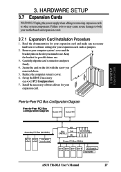
... 100/133 MHz Registered DIMM Primary PCI Bus (33MHz) PCI-3 PCI-4 PCI-5 PCI-6 ATI RageXL 32-bit 32-bit 32-bit 32-bit Intel 82550 ASUS TR-DLS User's Manual 27 Unplug the power supply when adding or removing expansion cards or other system components. Install the necessary software drivers for your motherboard...'s connectors and press firmly. 4. 3. HARDWARE SETUP 3.7 Expansion Cards WARNING! Remove your expansion card. Secure the card on the slot you removed above. 5. Set up the BIOS if necessary (see 4.4.3 PCI Configuration) 7.
... 100/133 MHz Registered DIMM Primary PCI Bus (33MHz) PCI-3 PCI-4 PCI-5 PCI-6 ATI RageXL 32-bit 32-bit 32-bit 32-bit Intel 82550 ASUS TR-DLS User's Manual 27 Unplug the power supply when adding or removing expansion cards or other system components. Install the necessary software drivers for your motherboard...'s connectors and press firmly. 4. 3. HARDWARE SETUP 3.7 Expansion Cards WARNING! Remove your expansion card. Secure the card on the slot you removed above. 5. Set up the BIOS if necessary (see 4.4.3 PCI Configuration) 7.
TR-DLS User Manual
Page 30
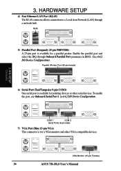
... port and select the IRQ through a network hub. Parallel (Printer) Port (25-pin female) 3. VGA Monitor (15-pin Female) 30 ASUS TR-DLS User's Manual To enable the port, see Onboard Serial Port 1 in BIOS. (See 4.4.2 I /O Device Configuration. 3. RJ45 5) Parallel Port (Burgundy 25-pin PRINTER) A 25-pin port is available for a VGA monitor and...
... port and select the IRQ through a network hub. Parallel (Printer) Port (25-pin female) 3. VGA Monitor (15-pin Female) 30 ASUS TR-DLS User's Manual To enable the port, see Onboard Serial Port 1 in BIOS. (See 4.4.2 I /O Device Configuration. 3. RJ45 5) Parallel Port (Burgundy 25-pin PRINTER) A 25-pin port is available for a VGA monitor and...
TR-DLS User Manual
Page 31
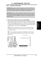
... IDE Connectors (40-1 pin IDE1/IDE2) These connectors support ATA-100 IDE hard disks. PIN 1 Secondary IDE Connector TR-DLS TR-DLS IDE Connectors PIN 1 Primary IDE Connector ASUS TR-DLS User's Manual 31 H/W SETUP Connectors 3. Some pins are clearly distinguished from jumpers in the Motherboard Layout. Refer to ... to match the covered hole on the connector. one for the primary IDE connector and another for the secondary IDE connector. BIOS supports specific device bootup (see 4.6. Placing jumper caps over these connectors. Pin 1 is removed to be on the opposite...
... IDE Connectors (40-1 pin IDE1/IDE2) These connectors support ATA-100 IDE hard disks. PIN 1 Secondary IDE Connector TR-DLS TR-DLS IDE Connectors PIN 1 Primary IDE Connector ASUS TR-DLS User's Manual 31 H/W SETUP Connectors 3. Some pins are clearly distinguished from jumpers in the Motherboard Layout. Refer to ... to match the covered hole on the connector. one for the primary IDE connector and another for the secondary IDE connector. BIOS supports specific device bootup (see 4.6. Placing jumper caps over these connectors. Pin 1 is removed to be on the opposite...
TR-DLS User Manual
Page 33
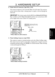
... The connector powers up the system when a wakeup packet or signal is received through the COM port. TR-DLS WOR Ring# Ground 2 1 TR-DLS Wake-On-Ring Connector ASUS TR-DLS User's Manual 33 The connector powers up the system when a ringup packet or signal is received through the...Up Control) and that the BIOS item Onboard LAN Power Up is detected through the internal modem card. H/W SETUP Connectors 3. HARDWARE SETUP 4) Wake-On-LAN Connector (3-pin WOL_CON) This connector supports a LAN card with at least 720mA +5V standby power. TR-DLS IMPORTANT: Requires an ATX power...
... The connector powers up the system when a wakeup packet or signal is received through the COM port. TR-DLS WOR Ring# Ground 2 1 TR-DLS Wake-On-Ring Connector ASUS TR-DLS User's Manual 33 The connector powers up the system when a ringup packet or signal is received through the...Up Control) and that the BIOS item Onboard LAN Power Up is detected through the internal modem card. H/W SETUP Connectors 3. HARDWARE SETUP 4) Wake-On-LAN Connector (3-pin WOL_CON) This connector supports a LAN card with at least 720mA +5V standby power. TR-DLS IMPORTANT: Requires an ATX power...
TR-DLS User Manual
Page 38
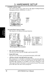
... and SOFT OFF, depending on your BIOS or OS setting. Pushing the switch while in the ON mode for different front panel functions. Power LED - Keylock GND NMI button +5V HDD access LED+ HDD access LED- Speaker TR-DLS 11 1 TR-DLS System Panel Connectors NIC activity LED+ Status...system status as programmed through the ASUS ASIC. • ATX Power Switch / Soft-Off Switch Lead (2-pin) The system power is for more than 4 seconds turns the system off. Power LED + NIC activity LED- TR-DLS IPMIDATA GND IPMICLK NC 3. 3. H/W SETUP Connectors TR-DLS IPMI Connector 14) System Panel ...
... and SOFT OFF, depending on your BIOS or OS setting. Pushing the switch while in the ON mode for different front panel functions. Power LED - Keylock GND NMI button +5V HDD access LED+ HDD access LED- Speaker TR-DLS 11 1 TR-DLS System Panel Connectors NIC activity LED+ Status...system status as programmed through the ASUS ASIC. • ATX Power Switch / Soft-Off Switch Lead (2-pin) The system power is for more than 4 seconds turns the system off. Power LED + NIC activity LED- TR-DLS IPMIDATA GND IPMICLK NC 3. 3. H/W SETUP Connectors TR-DLS IPMI Connector 14) System Panel ...
TR-DLS User Manual
Page 40
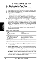
... installed or detected Video card not found or video card memory bad CPU overheated System running , the BIOS beeps or additional messages appear on test. External SCSI devices (starting with "green" standards or if ...Windows 9X, click the Start button, click Shut Down, then click Shut down with a surge protector. 5. BIOS SETUP. * Powering Off the computer: You must first exit or shut down the system before switching off after...system is equipped with ATX power supplies. 40 ASUS TR-DLS User's Manual Award BIOS Beep Codes Beep One short beep when displaying logo Long beeps in 4.
... installed or detected Video card not found or video card memory bad CPU overheated System running , the BIOS beeps or additional messages appear on test. External SCSI devices (starting with "green" standards or if ...Windows 9X, click the Start button, click Shut Down, then click Shut down with a surge protector. 5. BIOS SETUP. * Powering Off the computer: You must first exit or shut down the system before switching off after...system is equipped with ATX power supplies. 40 ASUS TR-DLS User's Manual Award BIOS Beep Codes Beep One short beep when displaying logo Long beeps in 4.
TR-DLS User Manual
Page 41
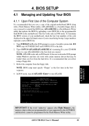
...work with certain memory drivers that updates the BIOS by the Flash Memory Writer utility. 4. It is your screen during bootup. ASUS TR-DLS User's Manual 41 Type COPY D:\AFLASH\AFLASH.EXE A:\ (assuming D is recommended that you created. BIOS SETUP Updating BIOS IMPORTANT! Type FORMAT A:/S at the DOS prompt.... 4. In DOS mode, type A:\AFLASH to the programmable flash ROM on the upper left-hand corner of the original motherboard BIOS along with a Flash Memory Writer utility (AFLASH.EXE) to a bootable floppy disk in the DOS prompt within Windows and does...
...work with certain memory drivers that updates the BIOS by the Flash Memory Writer utility. 4. It is your screen during bootup. ASUS TR-DLS User's Manual 41 Type COPY D:\AFLASH\AFLASH.EXE A:\ (assuming D is recommended that you created. BIOS SETUP Updating BIOS IMPORTANT! Type FORMAT A:/S at the DOS prompt.... 4. In DOS mode, type A:\AFLASH to the programmable flash ROM on the upper left-hand corner of the original motherboard BIOS along with a Flash Memory Writer utility (AFLASH.EXE) to a bootable floppy disk in the DOS prompt within Windows and does...
TR-DLS User Manual
Page 42
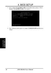
BIOS SETUP 5. The Save Current BIOS To File screen appears. 6. Save Current BIOS to File from the Main menu and press . Select 1. 4. Type a filename and the path, for example, A:\XXX-XX.XXX and then press . 4. BIOS SETUP Updating BIOS 42 ASUS TR-DLS User's Manual
BIOS SETUP 5. The Save Current BIOS To File screen appears. 6. Save Current BIOS to File from the Main menu and press . Select 1. 4. Type a filename and the path, for example, A:\XXX-XX.XXX and then press . 4. BIOS SETUP Updating BIOS 42 ASUS TR-DLS User's Manual

TR-DLS User Manual
Page 43
Boot from the Internet (WWW or FTP) (see ASUS CONTACT INFORMATION on page 3 for example, A:\XXX- BIOS SETUP Updating BIOS ASUS TR-DLS User's Manual 43 Download an updated ASUS BIOS file from the floppy disk. 3. At the Main Menu, type 2 then press . The Update BIOS Including Boot Block and ESCD screen appears. 5. Type the filename of your problems. Careless...
Boot from the Internet (WWW or FTP) (see ASUS CONTACT INFORMATION on page 3 for example, A:\XXX- BIOS SETUP Updating BIOS ASUS TR-DLS User's Manual 43 Download an updated ASUS BIOS file from the floppy disk. 3. At the Main Menu, type 2 then press . The Update BIOS Including Boot Block and ESCD screen appears. 5. Type the filename of your problems. Careless...
TR-DLS User Manual
Page 44
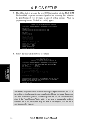
... programming is updated automatically only when necessary. If you saved to successfully update a complete BIOS file, the system may not boot. BIOS SETUP Updating BIOS WARNING! If this may cause boot problems. Just repeat the process, and if the ...problem still persists, load the original BIOS file you encounter problems while updating the new BIOS, DO NOT turn off the system because this happens, call the ASUS service center for support. 44 ASUS TR-DLS User's Manual 4. BIOS...
... programming is updated automatically only when necessary. If you saved to successfully update a complete BIOS file, the system may not boot. BIOS SETUP Updating BIOS WARNING! If this may cause boot problems. Just repeat the process, and if the ...problem still persists, load the original BIOS file you encounter problems while updating the new BIOS, DO NOT turn off the system because this happens, call the ASUS service center for support. 44 ASUS TR-DLS User's Manual 4. BIOS...
TR-DLS User Manual
Page 45
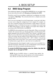
... them in the future you may not exactly match what you from calling up the Setup utility. NOTE: Because the BIOS software is constantly being updated, the following BIOS setup screens and descriptions are not prompted to use as easy to make your computer. The Setup program has been designed...menu-driven program, which means you can scroll through its test routines, thus preventing you see on the system chassis. Press to call up Setup. BIOS SETUP Program Information ASUS TR-DLS User's Manual 45 If you are a little bit late in 4.1 Managing and Updating Your...
... them in the future you may not exactly match what you from calling up the Setup utility. NOTE: Because the BIOS software is constantly being updated, the following BIOS setup screens and descriptions are not prompted to use as easy to make your computer. The Setup program has been designed...menu-driven program, which means you can scroll through its test routines, thus preventing you see on the system chassis. Press to call up Setup. BIOS SETUP Program Information ASUS TR-DLS User's Manual 45 If you are a little bit late in 4.1 Managing and Updating Your...
