Spresso Hardware User Manual
Page 3
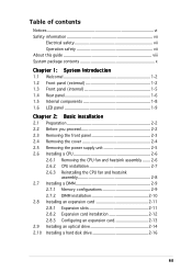
... 1-2 1.3 Front panel (internal 1-5 1.4 Rear panel 1-6 1.5 Internal components 1-8 1.6 LED panel 1-9 Chapter 2: Basic installation 2.1 Preparation 2-2 2.2 Before you proceed 2-2 2.3 Removing the front panel 2-3 2.4 Removing the cover 2-4 2.5 Removing the power supply unit 2-5 2.6 Installing a CPU 2-6 2.6.1 Removing the CPU fan and heatsink assembly ....... 2-6 2.6.2 CPU installation 2-7 2.6.3 Reinstalling the CPU fan and heatsink assembly 2-8 2.7 Installing a DIMM 2-9 2.7.1 Memory configurations 2-9 2.7.2 DIMM installation...
... 1-2 1.3 Front panel (internal 1-5 1.4 Rear panel 1-6 1.5 Internal components 1-8 1.6 LED panel 1-9 Chapter 2: Basic installation 2.1 Preparation 2-2 2.2 Before you proceed 2-2 2.3 Removing the front panel 2-3 2.4 Removing the cover 2-4 2.5 Removing the power supply unit 2-5 2.6 Installing a CPU 2-6 2.6.1 Removing the CPU fan and heatsink assembly ....... 2-6 2.6.2 CPU installation 2-7 2.6.3 Reinstalling the CPU fan and heatsink assembly 2-8 2.7 Installing a DIMM 2-9 2.7.1 Memory configurations 2-9 2.7.2 DIMM installation...
Spresso Hardware User Manual
Page 4
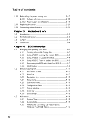
...contents 2.11 2.11 2.12 Reinstalling the power supply unit 2-17 2.11.1 Voltage selector 2-18 2.11.2 Power supply specifications 2-19 Replacing the cover 2-20 ...Connecting external devices 2-21 Chapter 3: Motherboard info 3.1 Introduction 3-2 3.2 Motherboard layout 3-2 3.3 Jumper 3-3 3.4 Connectors 3-4 Chapter 4: BIOS information 4.1 Managing and updating your BIOS 4-2 4.1.1 Creating a bootable floppy disk 4-2 4.1.2 Using AFUDOS to copy the current BIOS 4-3 4.1.3 Using AFUDOS to update the BIOS 4-4 4.1.4 Using ASUS...
...contents 2.11 2.11 2.12 Reinstalling the power supply unit 2-17 2.11.1 Voltage selector 2-18 2.11.2 Power supply specifications 2-19 Replacing the cover 2-20 ...Connecting external devices 2-21 Chapter 3: Motherboard info 3.1 Introduction 3-2 3.2 Motherboard layout 3-2 3.3 Jumper 3-3 3.4 Connectors 3-4 Chapter 4: BIOS information 4.1 Managing and updating your BIOS 4-2 4.1.1 Creating a bootable floppy disk 4-2 4.1.2 Using AFUDOS to copy the current BIOS 4-3 4.1.3 Using AFUDOS to update the BIOS 4-4 4.1.4 Using ASUS...
Spresso Hardware User Manual
Page 7
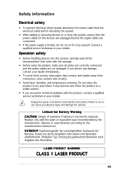
...came with the package. • Before using the product, make sure all cables are correctly connected and the power cables are connected. • If the power supply is incorrectly replaced. Dispose of explosion if battery is broken, do so can cause you physical injury and ...problems with the same or equivalent type recommended by yourself. Safety information Electrical safety • To prevent electrical shock hazard, disconnect the power cable from the electrical outlet before relocating the system. • When adding or removing devices to or from connectors, slots, sockets...
...came with the package. • Before using the product, make sure all cables are correctly connected and the power cables are connected. • If the power supply is incorrectly replaced. Dispose of explosion if battery is broken, do so can cause you physical injury and ...problems with the same or equivalent type recommended by yourself. Safety information Electrical safety • To prevent electrical shock hazard, disconnect the power cable from the electrical outlet before relocating the system. • When adding or removing devices to or from connectors, slots, sockets...
Spresso Hardware User Manual
Page 10
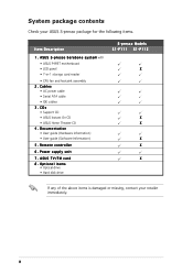
... • Hard disk drive S-presso Models S1-P111 S1-P112 X X X X X X If any of the above items is damaged or missing, contact your ASUS S-presso package for the following items. Item Description 1 . p r e s s o b a r e b o n e s y s t e m with • ASUS P4P8T motherboard • LED panel • 7-in-1 storage card reader • CPU fan and heatsink assembly 2 . Cables • AC power cable • Serial ATA...
... • Hard disk drive S-presso Models S1-P111 S1-P112 X X X X X X If any of the above items is damaged or missing, contact your ASUS S-presso package for the following items. Item Description 1 . p r e s s o b a r e b o n e s y s t e m with • ASUS P4P8T motherboard • LED panel • 7-in-1 storage card reader • CPU fan and heatsink assembly 2 . Cables • AC power cable • Serial ATA...
Spresso Hardware User Manual
Page 16
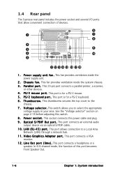
...8 2 3 9 4 10 5 11 12 13 14 15 16 17 18 1 . C h a s s i s f a n . This fan provides ventilation inside the power supply unit. 2 . This port is for a PS/2 keyboard. 6 . This port connects an external audio output device via an optical S/PDIF cable. 1 0 . V i d... e o G r a p h i c s A d a p t e r p o r t . This thumbscrew secures the top cover to the chassis. 7 . 1.4 Rear panel The S-presso rear panel includes the power socket and several I F O u t p o r t . This port connects a headphone or a speaker. P o w e r s o c k e t . P S / 2 m o u s e p o r ...
...8 2 3 9 4 10 5 11 12 13 14 15 16 17 18 1 . C h a s s i s f a n . This fan provides ventilation inside the power supply unit. 2 . This port is for a PS/2 keyboard. 6 . This port connects an external audio output device via an optical S/PDIF cable. 1 0 . V i d... e o G r a p h i c s A d a p t e r p o r t . This thumbscrew secures the top cover to the chassis. 7 . 1.4 Rear panel The S-presso rear panel includes the power socket and several I F O u t p o r t . This port connects a headphone or a speaker. P o w e r s o c k e t . P S / 2 m o u s e p o r ...
Spresso Hardware User Manual
Page 22
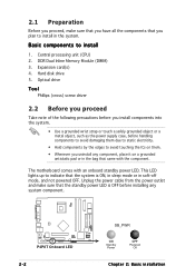
... to install in the bag that came with an onboard standby power LED. P4P8T ® P4P8T Onboard LED 2-2 SB_PWR ON Standby Power OFF Powered Off Chapter 2: Basic installation 2.1 Preparation Before you proceed, make sure that the standby power LED is ON, in sleep mode or in soft-off mode... into the system. • Use a grounded wrist strap or touch a safely grounded object or a metal object, such as the power supply case, before installing any component, place it on them. • Whenever you plan to install 1. Expansion card(s) 4. Central processing unit (CPU) 2.
... to install in the bag that came with an onboard standby power LED. P4P8T ® P4P8T Onboard LED 2-2 SB_PWR ON Standby Power OFF Powered Off Chapter 2: Basic installation 2.1 Preparation Before you proceed, make sure that the standby power LED is ON, in sleep mode or in soft-off mode... into the system. • Use a grounded wrist strap or touch a safely grounded object or a metal object, such as the power supply case, before installing any component, place it on them. • Whenever you plan to install 1. Expansion card(s) 4. Central processing unit (CPU) 2.
Spresso Hardware User Manual
Page 25
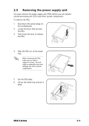
... PSU: 1. Slide the PSU out of the metal tray. Push down the lever to hold or support it aside. ASUS S-presso 2-5 Disconnect the power plugs on the motherboard. 2. 2.5 Removing the power supply unit You must remove the power supply unit (PSU) before you can install a central processing unit (CPU) and other system components. 5. When removing the PSU...
... PSU: 1. Slide the PSU out of the metal tray. Push down the lever to hold or support it aside. ASUS S-presso 2-5 Disconnect the power plugs on the motherboard. 2. 2.5 Removing the power supply unit You must remove the power supply unit (PSU) before you can install a central processing unit (CPU) and other system components. 5. When removing the PSU...
Spresso Hardware User Manual
Page 35
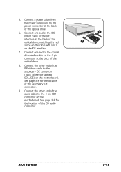
...of the optical drive audio cable to the 4-pin connector at the back of the optical drive. 8. Connect a power cable from the power supply unit to the power connector at the back of the IDE ribbon cable to the 4-pin CD1 connector on the motherboard. Connect the ...other end of the optical drive. 6. See page 3-8 for the location of the secondary IDE connector. 9. 5. See page 3-8 for the location of the CD audio connector. 5 6 7 ASUS S-presso...
...of the optical drive audio cable to the 4-pin connector at the back of the optical drive. 8. Connect a power cable from the power supply unit to the power connector at the back of the IDE ribbon cable to the 4-pin CD1 connector on the motherboard. Connect the ...other end of the optical drive. 6. See page 3-8 for the location of the secondary IDE connector. 9. 5. See page 3-8 for the location of the CD audio connector. 5 6 7 ASUS S-presso...
Spresso Hardware User Manual
Page 36
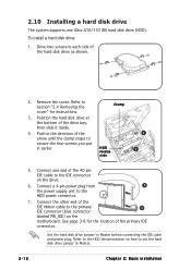
... hard disk drive jumper to Master before connecting the IDE cable and power plug. To install a hard disk drive: 1. 2.10 Installing a hard disk drive The system supports one end of the 40-pin IDE cable to the IDE connector on the drive. 6. Connect a 4-pin power plug from 5 the power supply unit to the HDD...
... hard disk drive jumper to Master before connecting the IDE cable and power plug. To install a hard disk drive: 1. 2.10 Installing a hard disk drive The system supports one end of the 40-pin IDE cable to the IDE connector on the drive. 6. Connect a 4-pin power plug from 5 the power supply unit to the HDD...
Spresso Hardware User Manual
Page 37
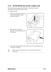
Make sure that the PSU cables do not interfere with the CPU and/or chassis fans. Make sure that the hooks align to the connectors on the motherboard. See next page for details. To reinstall the PSU: 1. Replace the metal tray. ASUS S-presso 2-17 2.11 Reinstalling the power supply unit Re-install the power supply unit (PSU) after installing the system components and reconnecting the cables. Connect the power plugs to their respective grooves. 2. Slide the PSU toward the direction of the rear panel until it fits in place. 3.
Make sure that the PSU cables do not interfere with the CPU and/or chassis fans. Make sure that the hooks align to the connectors on the motherboard. See next page for details. To reinstall the PSU: 1. Replace the metal tray. ASUS S-presso 2-17 2.11 Reinstalling the power supply unit Re-install the power supply unit (PSU) after installing the system components and reconnecting the cables. Connect the power plugs to their respective grooves. 2. Slide the PSU toward the direction of the rear panel until it fits in place. 3.
Spresso Hardware User Manual
Page 38
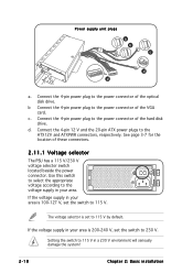
Power supply unit plugs a b c d d a. Connect the 4-pin 12 V and the 20-pin ATX power plugs to 115 V. Setting the switch to 115 V in your area. Connect the 4-pin power plug to 115 V by default. d. If the voltage supply in your area is 200-240 V, set the switch to the voltage supply in a 230 ...hard disk drive. Connect the 4-pin power plug to the power connector of the optical disk drive. b Connect the 4-pin power plug to the power connector of the VGA card. Use this switch to select the appropriate voltage according to 230 V. If the voltage supply in your area is 100-127 ...
Power supply unit plugs a b c d d a. Connect the 4-pin 12 V and the 20-pin ATX power plugs to 115 V. Setting the switch to 115 V in your area. Connect the 4-pin power plug to 115 V by default. d. If the voltage supply in your area is 200-240 V, set the switch to the voltage supply in a 230 ...hard disk drive. Connect the 4-pin power plug to the power connector of the optical disk drive. b Connect the 4-pin power plug to the power connector of the VGA card. Use this switch to select the appropriate voltage according to 230 V. If the voltage supply in your area is 100-127 ...
Spresso Hardware User Manual
Page 39
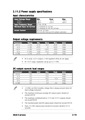
2.11.2 Power supply specifications Input characteristics Input Voltage Range Range 1 Range 2 Input Frequency... Volts • At no load, +3.3 V output +/-5% regulation limits do not apply. • At +12 V surge, regulation can go up to +/-10%. ASUS S-presso 2-19 DC output current load ranges Parameter +3.3 V +5 V +12 V -12 V +5 VSB Min 0.5 0.3 1.0 0.0 0.0 Nom - Max 17.0 13.0...that is always present when AC main voltage is present. • The maximum continuous average DC output power should not exceed 220 W. • The maximum combined load on +5 V and +3.3 V outputs should not exceed...
2.11.2 Power supply specifications Input characteristics Input Voltage Range Range 1 Range 2 Input Frequency... Volts • At no load, +3.3 V output +/-5% regulation limits do not apply. • At +12 V surge, regulation can go up to +/-10%. ASUS S-presso 2-19 DC output current load ranges Parameter +3.3 V +5 V +12 V -12 V +5 VSB Min 0.5 0.3 1.0 0.0 0.0 Nom - Max 17.0 13.0...that is always present when AC main voltage is present. • The maximum continuous average DC output power should not exceed 220 W. • The maximum combined load on +5 V and +3.3 V outputs should not exceed...
Spresso Hardware User Manual
Page 49
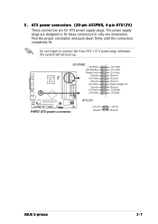
... connect the 4-pin ATX +12 V power plug; The power supply plugs are for ATX power supply plugs. Do not forget to fit these connectors in only one orientation. otherwise, the system will not boot up. ATXPWR +12.0Volts +5V Standby Power Good Ground +5.0 Volts Ground +5.0 Volts... Ground +3.3 Volts +3.3 Volts P4P8T ® P4P8T ATX power connector ATX12V +12V DC Ground +5.0 Volts +5.0 Volts -5.0 Volts Ground Ground Ground Power Supply On Ground -12.0Volts +3.3Volts +12V DC Ground ASUS S-presso 3-7 Find the proper ...
... connect the 4-pin ATX +12 V power plug; The power supply plugs are for ATX power supply plugs. Do not forget to fit these connectors in only one orientation. otherwise, the system will not boot up. ATXPWR +12.0Volts +5V Standby Power Good Ground +5.0 Volts Ground +5.0 Volts... Ground +3.3 Volts +3.3 Volts P4P8T ® P4P8T ATX power connector ATX12V +12V DC Ground +5.0 Volts +5.0 Volts -5.0 Volts Ground Ground Ground Power Supply On Ground -12.0Volts +3.3Volts +12V DC Ground ASUS S-presso 3-7 Find the proper ...
Spresso Hardware User Manual
Page 53
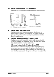
...Ground PWR P4P8T ® P4P8T System panel connector ATX Power Switch* * Requires an ATX power supply. • System power LED (2-pin PLED) This 3-pin connector is for more than four seconds while the system is ON turns the system OFF. ASUS S-presso 3-11 The IDE LED lights up when you turn ...on the BIOS settings. Pressing the power button turns the system...
...Ground PWR P4P8T ® P4P8T System panel connector ATX Power Switch* * Requires an ATX power supply. • System power LED (2-pin PLED) This 3-pin connector is for more than four seconds while the system is ON turns the system OFF. ASUS S-presso 3-11 The IDE LED lights up when you turn ...on the BIOS settings. Pressing the power button turns the system...
Spresso Hardware User Manual
Page 81
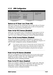
... the computer and applications are fully running. Thus, connection cannot be made on . This feature requires an ATX power supply that provides at least 1A on the +5VSB lead. Configuration options: [Disabled] [Enabled] ASUS S-presso 4-27 When this parameter allows you to use specific keys on the system. Turning an external modem off and...
... the computer and applications are fully running. Thus, connection cannot be made on . This feature requires an ATX power supply that provides at least 1A on the +5VSB lead. Configuration options: [Disabled] [Enabled] ASUS S-presso 4-27 When this parameter allows you to use specific keys on the system. Turning an external modem off and...


