
User Manual
Page 4
... rail kit items 3-2 3.2 Rack rails assembly 3-2 3.3 Attaching the rails to the rack 3-3 3.4 Rackmounting the server 3-4 Chapter 4: Motherboard information 4.1 Motherboard layout 4-2 4.2 Jumpers 4-4 4.3 Internal connectors 4-8 Chapter 5: BIOS setup 5.1 Managing and updating your... BIOS 5-2 5.1.1 Creating a bootable floppy disk 5-2 5.1.2 AFUDOS utility 5-3 5.1.3 ASUS CrashFree BIOS 2 utility 5-6 5.1.4 ASUS Update utility 5-8 5.2 BIOS setup program 5-11 5.2.1 BIOS menu screen 5-12 5.2.2 Menu bar 5-12 5.2.3 Navigation keys 5-12...
... rail kit items 3-2 3.2 Rack rails assembly 3-2 3.3 Attaching the rails to the rack 3-3 3.4 Rackmounting the server 3-4 Chapter 4: Motherboard information 4.1 Motherboard layout 4-2 4.2 Jumpers 4-4 4.3 Internal connectors 4-8 Chapter 5: BIOS setup 5.1 Managing and updating your... BIOS 5-2 5.1.1 Creating a bootable floppy disk 5-2 5.1.2 AFUDOS utility 5-3 5.1.3 ASUS CrashFree BIOS 2 utility 5-6 5.1.4 ASUS Update utility 5-8 5.2 BIOS setup program 5-11 5.2.1 BIOS menu screen 5-12 5.2.2 Menu bar 5-12 5.2.3 Navigation keys 5-12...

User Manual
Page 5
... 5.4.1 CPU Configuration 5-20 5.4.2 Chipset Configuration 5-21 5.4.3 PCI PnP 5-23 5.4.4 USB Configuration 5-24 5.4.5 Peripheral Devices Configuration 5-25 5.4.6 ACPI Configuration 5-26 5.4.7 APM Configuration 5-27 5.4.8 Hardware Monitor 5-28 5.5 Server menu 5-30 5.6 Security menu 5-32 5.7 Boot menu 5-35 5.7.1 Boot Device Priority 5-35 5.7.2 Boot Settings Configuration 5-36 5.8 Exit menu 5-38 Chapter 6: RAID configuration 6.1 Setting up RAID...
... 5.4.1 CPU Configuration 5-20 5.4.2 Chipset Configuration 5-21 5.4.3 PCI PnP 5-23 5.4.4 USB Configuration 5-24 5.4.5 Peripheral Devices Configuration 5-25 5.4.6 ACPI Configuration 5-26 5.4.7 APM Configuration 5-27 5.4.8 Hardware Monitor 5-28 5.5 Server menu 5-30 5.6 Security menu 5-32 5.7 Boot menu 5-35 5.7.1 Boot Device Priority 5-35 5.7.2 Boot Settings Configuration 5-36 5.8 Exit menu 5-38 Chapter 6: RAID configuration 6.1 Setting up RAID...

User Manual
Page 8
...temperature extremes. Dispose of explosion if battery is heavy. Use the power cable with the same or equivalent type recommended by yourself. This server system is incorrectly replaced. Danger of used batteries according to fix it by the manufacturer. CD-ROM Drive Safety Warning CLASS 1 LASER ... that the power cables for the devices are unplugged before the signal cables are connected. This product is equipped with the server package. • Before using the server, make sure all power cables from the existing system before you add a device. • If the power supply is...
...temperature extremes. Dispose of explosion if battery is heavy. Use the power cable with the same or equivalent type recommended by yourself. This server system is incorrectly replaced. Danger of used batteries according to fix it by the manufacturer. CD-ROM Drive Safety Warning CLASS 1 LASER ... that the power cables for the devices are unplugged before the signal cables are connected. This product is equipped with the server package. • Before using the server, make sure all power cables from the existing system before you add a device. • If the power supply is...
User Manual
Page 9
... Chapter 7: Driver installation This chapter provides instructions for installing the necessary drivers for system integrators, and experienced users with the server. About this guide Audience This user guide is intended for different system components. 8. Chapter 3: Installation options This chapter describes... 1. Chapter 4: Motherboard information This chapter gives information about the motherboard that comes with at least basic knowledge of the server, including sections on front panel and rear panel specifications. 2. Chapter 2: Hardware setup This chapter lists the hardware setup ...
... Chapter 7: Driver installation This chapter provides instructions for installing the necessary drivers for system integrators, and experienced users with the server. About this guide Audience This user guide is intended for different system components. 8. Chapter 3: Installation options This chapter describes... 1. Chapter 4: Motherboard information This chapter gives information about the motherboard that comes with at least basic knowledge of the server, including sections on front panel and rear panel specifications. 2. Chapter 2: Hardware setup This chapter lists the hardware setup ...

User Manual
Page 10
...a word or a phrase. Example: At the DOS prompt, type the command line: format A:/S Refer to aid in brackets. x ASUS Server Web-based Management (ASWM) user guide This manual tells how to select. Example: Means that you must type the command exactly as ...task. Typography Bold text Italics Command References Indicates a menu or an item to set up and use the proprietary ASUS server management utility. 2. ASUS websites The ASUS websites worldwide provide updated information for product and software updates. 1 . Example: means that you perform certain tasks properly...
...a word or a phrase. Example: At the DOS prompt, type the command line: format A:/S Refer to aid in brackets. x ASUS Server Web-based Management (ASWM) user guide This manual tells how to select. Example: Means that you must type the command exactly as ...task. Typography Bold text Italics Command References Indicates a menu or an item to set up and use the proprietary ASUS server management utility. 2. ASUS websites The ASUS websites worldwide provide updated information for product and software updates. 1 . Example: means that you perform certain tasks properly...

User Manual
Page 13
... r e q u i r e m e n t 500 W power supply, 100~240 VAC, 47~63 Hz Dimensions 663 mm (l) x 444 mm (w) x 43.6 mm (h) ASUS RS161-E2/PA2 1-3 The server supports dual 940-pin AMD Opteron™ 64 processors, and includes the latest technologies through the chipsets embedded on this motherboard due to 4 GB...Gigabit PCI-E LAN controllers VGA ATI RAGE-XL PCI-based VGA controller with 8 MB display memory Expansion slots 2 x PCI Express™ x16 slots (x8 link) 1 x mini-PCI socket for ASUS® Server Management Board Storage NVIDIA® nForce™ Professional 2200 chipset supports: - 2...
... r e q u i r e m e n t 500 W power supply, 100~240 VAC, 47~63 Hz Dimensions 663 mm (l) x 444 mm (w) x 43.6 mm (h) ASUS RS161-E2/PA2 1-3 The server supports dual 940-pin AMD Opteron™ 64 processors, and includes the latest technologies through the chipsets embedded on this motherboard due to 4 GB...Gigabit PCI-E LAN controllers VGA ATI RAGE-XL PCI-based VGA controller with 8 MB display memory Expansion slots 2 x PCI Express™ x16 slots (x8 link) 1 x mini-PCI socket for ASUS® Server Management Board Storage NVIDIA® nForce™ Professional 2200 chipset supports: - 2...

User Manual
Page 14
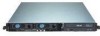
... Serial port USB ports PS/2 keyboard port PS/2 mouse port Power fan AC power socket Power fan 1-4 Chapter 1: Product introduction 1.3 Front panel features The barebone server displays a simple yet stylish front panel with openings for the rear panel connectors on the motherboard. Refer to section "1.6.1 Front panel LEDs" for the PS...
... Serial port USB ports PS/2 keyboard port PS/2 mouse port Power fan AC power socket Power fan 1-4 Chapter 1: Product introduction 1.3 Front panel features The barebone server displays a simple yet stylish front panel with openings for the rear panel connectors on the motherboard. Refer to section "1.6.1 Front panel LEDs" for the PS...
User Manual
Page 15
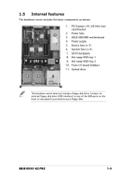
... HDD tray 1 5 9. Optical drive 8 9 11 10 The barebone server does not include a floppy disk drive. Power fans 4 3. System fans (x 4) 7. ASUS RS161-E2/PA2 1-5 ASUS K8N-DRE motherboard 3 4. Device fans (x 3) 6. Hot-swap HDD tray 2 10. PCI Express x16 (x8 link) riser 1 2 card bracket 2. 1.5 Internal features The barebone server includes the basic components as shown. 1. Power supply 5. SATA...
... HDD tray 1 5 9. Optical drive 8 9 11 10 The barebone server does not include a floppy disk drive. Power fans 4 3. System fans (x 4) 7. ASUS RS161-E2/PA2 1-5 ASUS K8N-DRE motherboard 3 4. Device fans (x 3) 6. Hot-swap HDD tray 2 10. PCI Express x16 (x8 link) riser 1 2 card bracket 2. 1.5 Internal features The barebone server includes the basic components as shown. 1. Power supply 5. SATA...

User Manual
Page 20
Refer to do so may cause you physical injury and may damage motherboard components. 2-4 Chapter 2: Hardware setup Failure to "Chapter 4 Motherboard information" for detailed information on the motherboard. K8N-DRE ¤ Make sure to the chassis by 10 screws as indicated by the circles in the illustration below. The motherboard is secured to unplug the power cord before installing or removing any motherboard component or connection. 2.2 Motherboard information The barebone server comes with the K8N-DRE motherboard already installed.
Refer to do so may cause you physical injury and may damage motherboard components. 2-4 Chapter 2: Hardware setup Failure to "Chapter 4 Motherboard information" for detailed information on the motherboard. K8N-DRE ¤ Make sure to the chassis by 10 screws as indicated by the circles in the illustration below. The motherboard is secured to unplug the power cord before installing or removing any motherboard component or connection. 2.2 Motherboard information The barebone server comes with the K8N-DRE motherboard already installed.

User Manual
Page 30
... setup Place the riser card bracket on the motherboard. 2. Remove the slot metal cover, then set it up to the riser card bracket The barebone server comes with a riser card bracket. To install the PCI Express x16 expansion cards: 1.
... setup Place the riser card bracket on the motherboard. 2. Remove the slot metal cover, then set it up to the riser card bracket The barebone server comes with a riser card bracket. To install the PCI Express x16 expansion cards: 1.
User Manual
Page 43
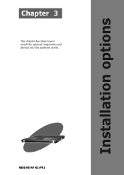
ASUS RS161-E2/PA2 2-1 Installation options Chapter 3 This chapter describes how to install the optional components and devices into the barebone server.
ASUS RS161-E2/PA2 2-1 Installation options Chapter 3 This chapter describes how to install the optional components and devices into the barebone server.

User Manual
Page 45
... the outer holes to secure the front end. 1U space 5. When properly installed, the rack rails appear as shown. ASUS RS161-E2 (PA2) 3-3 Select one unit of a rack rail pair to install the barebone server. 2. Find the r e a r 1 U s p a c e that corresponds to the f r o n t 1 U s p a c e where you wish to the 1U space. 4. Repeat steps 2 to 7 to the rack...
... the outer holes to secure the front end. 1U space 5. When properly installed, the rack rails appear as shown. ASUS RS161-E2 (PA2) 3-3 Select one unit of a rack rail pair to install the barebone server. 2. Find the r e a r 1 U s p a c e that corresponds to the f r o n t 1 U s p a c e where you wish to the 1U space. 4. Repeat steps 2 to 7 to the rack...

User Manual
Page 46
3.4 Rackmounting the server To mount the server to the rack. Rack screw 3-4 Chapter 3: Installation options Tighten the two rack screws to secure the server to the rack: 1. Firmly hold the server on both sides and insert the rear panel side to the front end of the rack rail, then carefully push the server all the way to the back until the front panel fits the front end of the rack, and the rack screws on the server match the middle hole on the rack.. 2.
3.4 Rackmounting the server To mount the server to the rack. Rack screw 3-4 Chapter 3: Installation options Tighten the two rack screws to secure the server to the rack: 1. Firmly hold the server on both sides and insert the rear panel side to the front end of the rack rail, then carefully push the server all the way to the back until the front panel fits the front end of the rack, and the rack screws on the server match the middle hole on the rack.. 2.

User Manual
Page 47
Motherboard info Chapter 4 This chapter gives information about the motherboard that comes with the server. This chapter includes the motherboard layout, jumper settings, and connector locations ASUS RS161-E2/PA2 2-1
Motherboard info Chapter 4 This chapter gives information about the motherboard that comes with the server. This chapter includes the motherboard layout, jumper settings, and connector locations ASUS RS161-E2/PA2 2-1

User Manual
Page 61
...panel. Devices communicate with an intrusion detection feature. This requires an external detection mechanism such as a chassis intrusion sensor or microswitch. ASUS RS161-E2 (PA2) 4-15 Connect the LAN2 Activity LED cable to record a chassis intrusion event. • LAN1 link activity LED (2-pin...-level signal to this lead to this connector. 12. System panel auxiliary connector (20-pin AUX_PANEL1) This connector supports several server system functions. Connect the LAN1 Activity LED cable to this connector. • Locator Button/Switch (2-pin LOCATORBTN) This connector ...
...panel. Devices communicate with an intrusion detection feature. This requires an external detection mechanism such as a chassis intrusion sensor or microswitch. ASUS RS161-E2 (PA2) 4-15 Connect the LAN2 Activity LED cable to record a chassis intrusion event. • LAN1 link activity LED (2-pin...-level signal to this lead to this connector. 12. System panel auxiliary connector (20-pin AUX_PANEL1) This connector supports several server system functions. Connect the LAN1 Activity LED cable to this connector. • Locator Button/Switch (2-pin LOCATORBTN) This connector ...

User Manual
Page 74
.... Some of a menu screen are the navigation keys for that particular menu. 5.2.1 BIOS menu screen Menu items Menu bar Configuration fields General help Main Advanced Server System Date System Time Floppy A: IDE Configuration Primary IDE Master Primary IDE Slave Secondary IDE Master Secondary IDE Slave Tertiary IDE Master Fourth IDE Master... Fifth IDE Master Sixth IDE Master System Information BIOS SETUP UTILITY Security Boot Exit [Mon, 06/27/2005] [08:52:30] [1.44 MB, 3.5 in the menu and change the settings. Use [+] or [-] to another. 5-12 Chapter 5: BIOS setup
.... Some of a menu screen are the navigation keys for that particular menu. 5.2.1 BIOS menu screen Menu items Menu bar Configuration fields General help Main Advanced Server System Date System Time Floppy A: IDE Configuration Primary IDE Master Primary IDE Slave Secondary IDE Master Secondary IDE Slave Tertiary IDE Master Fourth IDE Master... Fifth IDE Master Sixth IDE Master System Information BIOS SETUP UTILITY Security Boot Exit [Mon, 06/27/2005] [08:52:30] [1.44 MB, 3.5 in the menu and change the settings. Use [+] or [-] to another. 5-12 Chapter 5: BIOS setup

User Manual
Page 76
... M a i n menu screen appears, giving you to set the system date. 5.3.2 System Time [xx:xx:xx] Allows you an overview of floppy drive installed. Main Advanced Server System Date System Time Floppy A: IDE Configuration Primary IDE Master Primary IDE Slave Secondary IDE Master Secondary IDE Slave Tertiary IDE Master Fourth IDE Master...
... M a i n menu screen appears, giving you to set the system date. 5.3.2 System Time [xx:xx:xx] Allows you an overview of floppy drive installed. Main Advanced Server System Date System Time Floppy A: IDE Configuration Primary IDE Master Primary IDE Slave Secondary IDE Master Secondary IDE Slave Tertiary IDE Master Fourth IDE Master...

User Manual
Page 82
... version. Change Field Tab Select Field F1 General Help F10 Save and Exit ESC Exit V00.00 (C)Copyright 1985-2004, American Megatrends, Inc. Main Advanced Server BIOS SETUP UTILITY Security Boot Exit WARNING: Setting wrong values in this menu show the CPU-related information that the BIOS automatically detects. Configuration options...
... version. Change Field Tab Select Field F1 General Help F10 Save and Exit ESC Exit V00.00 (C)Copyright 1985-2004, American Megatrends, Inc. Main Advanced Server BIOS SETUP UTILITY Security Boot Exit WARNING: Setting wrong values in this menu show the CPU-related information that the BIOS automatically detects. Configuration options...

User Manual
Page 92
... Help F10 Save and Exit ESC Exit V00.00 (C)Copyright 1985-2004, American Megatrends, Inc. Remote Access [Disabled] Enables or disables the remote access feature. Server BIOS SETUP UTILITY Configure Remote Access type and parameters Remote Access [Disabled] →← Select Screen ↑↓ Select Item...
... Help F10 Save and Exit ESC Exit V00.00 (C)Copyright 1985-2004, American Megatrends, Inc. Remote Access [Disabled] Enables or disables the remote access feature. Server BIOS SETUP UTILITY Configure Remote Access type and parameters Remote Access [Disabled] →← Select Screen ↑↓ Select Item...

User Manual
Page 94
To set your BIOS password, you can clear it by erasing the CMOS Real Time Clock (RTC) RAM. Confirm the password when prompted. 5.6 Security menu The Security menu items allow you to change the supervisor password. Change Supervisor Password Select this...To change the user password, follow the same steps as in setting a supervisor password. The message "Password Uninstalled" appears. Main Advanced Server BIOS SETUP UTILITY Security Boot Exit Supervisor Password : Not Installed User Password : Not Installed Change Supervisor Password Install or Change the password....
To set your BIOS password, you can clear it by erasing the CMOS Real Time Clock (RTC) RAM. Confirm the password when prompted. 5.6 Security menu The Security menu items allow you to change the supervisor password. Change Supervisor Password Select this...To change the user password, follow the same steps as in setting a supervisor password. The message "Password Uninstalled" appears. Main Advanced Server BIOS SETUP UTILITY Security Boot Exit Supervisor Password : Not Installed User Password : Not Installed Change Supervisor Password Install or Change the password....