
PRL-DL M/B User Guide
Page 14
Chapter summary 1.1 Welcome 1-1 1.2 Package contents 1-1 1.3 Special features 1-2 1.4 Motherboard overview 1-6 ASUS PRL-DL motherboard
Chapter summary 1.1 Welcome 1-1 1.2 Package contents 1-1 1.3 Special features 1-2 1.4 Motherboard overview 1-6 ASUS PRL-DL motherboard
PRL-DL M/B User Guide
Page 15
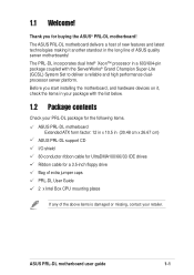
The ASUS PRL-DL motherboard delivers a host of new features and latest technologies making it , check the items in your retailer. The PRL-DL incorporates dual Intel® Xeon™ processor in the long line of the above items is damaged or missing, contact your package with...a 603/604-pin package coupled with the list below. 1.2 Package contents Check your PRL-DL package for the following items. ASUS PRL-DL motherboard Extended ATX form factor: 12 in x 10.5 in (30.48 cm x 26.67 cm) ASUS PRL-DL support CD I/O shield 80-conductor ribbon cable for UltraDMA100/66//33 IDE drives Ribbon cable...
The ASUS PRL-DL motherboard delivers a host of new features and latest technologies making it , check the items in your retailer. The PRL-DL incorporates dual Intel® Xeon™ processor in the long line of the above items is damaged or missing, contact your package with...a 603/604-pin package coupled with the list below. 1.2 Package contents Check your PRL-DL package for the following items. ASUS PRL-DL motherboard Extended ATX form factor: 12 in x 10.5 in (30.48 cm x 26.67 cm) ASUS PRL-DL support CD I/O shield 80-conductor ribbon cable for UltraDMA100/66//33 IDE drives Ribbon cable...
PRL-DL M/B User Guide
Page 17
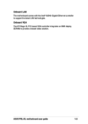
Onboard LAN The motherboard comes with the Intel® 82540 Gigabit Ethernet controller to provide onboard video solution. ASUS PRL-DL motherboard user guide 1-3 Onboard VGA The ATI Rage-XL PCI-based VGA controller integrates an 8MB display SDRAM to support the latest LAN technologies.
Onboard LAN The motherboard comes with the Intel® 82540 Gigabit Ethernet controller to provide onboard video solution. ASUS PRL-DL motherboard user guide 1-3 Onboard VGA The ATI Rage-XL PCI-based VGA controller integrates an 8MB display SDRAM to support the latest LAN technologies.
PRL-DL M/B User Guide
Page 19
... procedures for more control and protection to the motherboard. Color-coded connectors and descriptive icons make identification easy as required by the PC '99 specification. ASUS PRL-DL motherboard user guide 1-5 A chassis intrusion event is Year 2000 certified. Compliance Both the BIOS and the hardware levels of the motherboard meet the stringent requirements...
... procedures for more control and protection to the motherboard. Color-coded connectors and descriptive icons make identification easy as required by the PC '99 specification. ASUS PRL-DL motherboard user guide 1-5 A chassis intrusion event is Year 2000 certified. Compliance Both the BIOS and the hardware levels of the motherboard meet the stringent requirements...

PRL-DL M/B User Guide
Page 21
1 2 34 5 6 19 7 8 18 17 16 15 14 13 12 11 10 9 20 21 26 25 24 23 22 ASUS PRL-DL motherboard user guide 1-7
1 2 34 5 6 19 7 8 18 17 16 15 14 13 12 11 10 9 20 21 26 25 24 23 22 ASUS PRL-DL motherboard user guide 1-7
PRL-DL M/B User Guide
Page 23
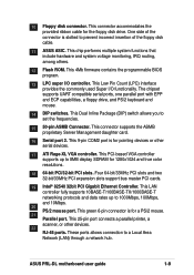
... PCI Gigabit Ethernet Controller. These ports allows connection to prevent incorrect insertion of the floppy disk cable. 11 ASUS ASIC. This green 6-pin connector is slotted to a Local Area Network (LAN) through a network hub. ASUS PRL-DL motherboard user guide 1-9 This chip performs multiple system functions that include hardware and system voltage monitoring, IRQ...
... PCI Gigabit Ethernet Controller. These ports allows connection to prevent incorrect insertion of the floppy disk cable. 11 ASUS ASIC. This green 6-pin connector is slotted to a Local Area Network (LAN) through a network hub. ASUS PRL-DL motherboard user guide 1-9 This chip performs multiple system functions that include hardware and system voltage monitoring, IRQ...

PRL-DL M/B User Guide
Page 26
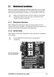
Chapter summary 2.1 Motherboard installation 2-1 2.2 Motherboard layout 2-2 2.3 Before you proceed 2-3 2.4 Central Processing Unit (CPU 2-4 2.5 System memory 2-8 2.6 Expansion slots 2-11 2.7 Switches and jumpers 2-14 2.8 Connectors 2-19 ASUS PRL-DL motherboard
Chapter summary 2.1 Motherboard installation 2-1 2.2 Motherboard layout 2-2 2.3 Before you proceed 2-3 2.4 Central Processing Unit (CPU 2-4 2.5 System memory 2-8 2.6 Expansion slots 2-11 2.7 Switches and jumpers 2-14 2.8 Connectors 2-19 ASUS PRL-DL motherboard
PRL-DL M/B User Guide
Page 27
The PRL-DL uses the extended ATX form factor that you place it . Make sure to ensure that the motherboard fits into it into the chassis in the ... towards the rear of the chassis as indicated in the correct orientation. The edge with external ports goes to the rear part of the chassis ASUS PRL-DL motherboard user guide 2-1 Do not overtighten the screws!
The PRL-DL uses the extended ATX form factor that you place it . Make sure to ensure that the motherboard fits into it into the chassis in the ... towards the rear of the chassis as indicated in the correct orientation. The edge with external ports goes to the rear part of the chassis ASUS PRL-DL motherboard user guide 2-1 Do not overtighten the screws!
PRL-DL M/B User Guide
Page 29
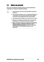
... wall socket before handling components to the motherboard, peripherals, and/or components. Unplug the power cord from the power supply. Whenever you uninstall any component. 2. ASUS PRL-DL motherboard user guide 2-3 2.3 Before you proceed Take note of the following precautions before you install motherboard components or change any component, ensure that came with...
... wall socket before handling components to the motherboard, peripherals, and/or components. Unplug the power cord from the power supply. Whenever you uninstall any component. 2. ASUS PRL-DL motherboard user guide 2-3 2.3 Before you proceed Take note of the following precautions before you install motherboard components or change any component, ensure that came with...
PRL-DL M/B User Guide
Page 31
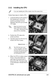
... lift it is locked. The lever clicks on the side tab to at least 115° angle, otherwise the CPU does not fit in place. ASUS PRL-DL motherboard user guide 2-5 Make sure that it up to secure the CPU. Position the CPU above the socket as shown. 3. When the CPU is lifted...
... lift it is locked. The lever clicks on the side tab to at least 115° angle, otherwise the CPU does not fit in place. ASUS PRL-DL motherboard user guide 2-5 Make sure that it up to secure the CPU. Position the CPU above the socket as shown. 3. When the CPU is lifted...
PRL-DL M/B User Guide
Page 33
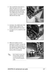
... the heatsink and fan assembly. Don't forget to plug the cable. Hardware monitoring problems may occur if you fail to connect the CPU fan cable. ASUS PRL-DL motherboard user guide 2-7 3. Use a small flat screw driver to the fan connector on the motherboard labeled FAN1 (for the CPU on socket 1) and FAN2 (for...
... the heatsink and fan assembly. Don't forget to plug the cable. Hardware monitoring problems may occur if you fail to connect the CPU fan cable. ASUS PRL-DL motherboard user guide 2-7 3. Use a small flat screw driver to the fan connector on the motherboard labeled FAN1 (for the CPU on socket 1) and FAN2 (for...
PRL-DL M/B User Guide
Page 35
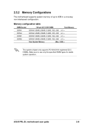
ASUS PRL-DL motherboard user guide 2-9 2.5.2 Memory Configurations The motherboard supports system memory of up to use only the specified DIMM types for stable system operation. Memory configuration ...
ASUS PRL-DL motherboard user guide 2-9 2.5.2 Memory Configurations The motherboard supports system memory of up to use only the specified DIMM types for stable system operation. Memory configuration ...
PRL-DL M/B User Guide
Page 37
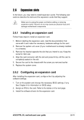
... screw you intend to use . 4. Secure the card to the chassis with the slot and press firmly until the card is already installed in a chassis). 3. ASUS PRL-DL motherboard user guide 2-11 Remove the bracket opposite the slot that they support. Failure to do so may cause you may need to install expansion...
... screw you intend to use . 4. Secure the card to the chassis with the slot and press firmly until the card is already installed in a chassis). 3. ASUS PRL-DL motherboard user guide 2-11 Remove the bracket opposite the slot that they support. Failure to do so may cause you may need to install expansion...
PRL-DL M/B User Guide
Page 39
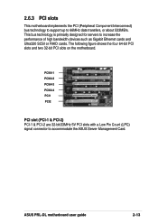
...PCI-2) PCI-1 & PCI-2 are 32-bit/33MHz 5V PCI slots with a Low Pin Count (LPC) signal connector to 66MHz data transfers, or about 533MB/s. ASUS PRL-DL motherboard user guide 2-13 2.6.3 PCI slots This motherboard implements the PCI (Peripheral Component Interconnect) bus technology to support up to accommodate the... ASUS Server Management Card. The following figure shows the four 64-bit PCI slots and two 32-bit PCI slots on the motherboard....
...PCI-2) PCI-1 & PCI-2 are 32-bit/33MHz 5V PCI slots with a Low Pin Count (LPC) signal connector to 66MHz data transfers, or about 533MB/s. ASUS PRL-DL motherboard user guide 2-13 2.6.3 PCI slots This motherboard implements the PCI (Peripheral Component Interconnect) bus technology to support up to accommodate the... ASUS Server Management Card. The following figure shows the four 64-bit PCI slots and two 32-bit PCI slots on the motherboard....
PRL-DL M/B User Guide
Page 41
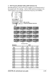
Set the DSW switches according to coordinate the ratio of your processor and the bus frequency (133/100MHz). ® PRL-DL SW2 PRL-DL CPU Frequency Multiple Selection 12345678 12345678 12345678 12345678 ON ON ON ON 8.0x 10.0x 11.0x 12.0x 12345678 12345678 12345678 ... [ON] [OFF] [OFF] [ON] [ON] [ON] 24.0x 8 [OFF] [OFF] [OFF] [OFF] [OFF] [OFF] [OFF] [ON] [ON] [ON] [ON] [ON] [ON] [ON] [OFF] [ON] ASUS PRL-DL motherboard user guide 2-15 2. CPU Frequency Multiple Setting (SW2 Switches 5-8) Set DSW switches (1-4) to use the clock multiplier to the internal speed of bus speeds...
Set the DSW switches according to coordinate the ratio of your processor and the bus frequency (133/100MHz). ® PRL-DL SW2 PRL-DL CPU Frequency Multiple Selection 12345678 12345678 12345678 12345678 ON ON ON ON 8.0x 10.0x 11.0x 12.0x 12345678 12345678 12345678 ... [ON] [OFF] [OFF] [ON] [ON] [ON] 24.0x 8 [OFF] [OFF] [OFF] [OFF] [OFF] [OFF] [OFF] [ON] [ON] [ON] [ON] [ON] [ON] [ON] [OFF] [ON] ASUS PRL-DL motherboard user guide 2-15 2. CPU Frequency Multiple Setting (SW2 Switches 5-8) Set DSW switches (1-4) to use the clock multiplier to the internal speed of bus speeds...
PRL-DL M/B User Guide
Page 43
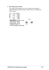
Reset to pins 2-3 to enable the onboard the onboard ATI Rage XL VGA controller. 3. VGA setting (3-pin JVGA1) This jumper is set by default, pins [1-2], to disable the VGA controller. ® PRL-DL JVGA1 12 23 PRL-DL ATI RageXL VGA Setting Enable (Default) Disable ASUS PRL-DL motherboard user guide 2-17
Reset to pins 2-3 to enable the onboard the onboard ATI Rage XL VGA controller. 3. VGA setting (3-pin JVGA1) This jumper is set by default, pins [1-2], to disable the VGA controller. ® PRL-DL JVGA1 12 23 PRL-DL ATI RageXL VGA Setting Enable (Default) Disable ASUS PRL-DL motherboard user guide 2-17
PRL-DL M/B User Guide
Page 45
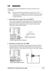
Pin 1 is removed to prevent incorrect insertion when using an optional serial port bracket. PRL-DL Floppy Disk Drive Connector 2. Always connect ribbon cables with pin 5 plug). FLOPPY1 ® PRL-DL PIN 1 NOTE: Orient the red markings on the motherboard. Connect the bracket cable to...closest to this connector then install the bracket into a slot opening at the back of the system chassis. ® PRL-DL COM2 PIN 1 PRL-DL Serial COM2 Connector ASUS PRL-DL motherboard user guide 2-19 Serial port 2 connector (10-1 pin COM2) This connector accommodates a second serial port using...
Pin 1 is removed to prevent incorrect insertion when using an optional serial port bracket. PRL-DL Floppy Disk Drive Connector 2. Always connect ribbon cables with pin 5 plug). FLOPPY1 ® PRL-DL PIN 1 NOTE: Orient the red markings on the motherboard. Connect the bracket cable to...closest to this connector then install the bracket into a slot opening at the back of the system chassis. ® PRL-DL COM2 PIN 1 PRL-DL Serial COM2 Connector ASUS PRL-DL motherboard user guide 2-19 Serial port 2 connector (10-1 pin COM2) This connector accommodates a second serial port using...
PRL-DL M/B User Guide
Page 47
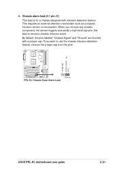
... wish to record a chassis intrusion event. By default, the pins labeled "Chassis Signal" and "Ground" are shorted with intrusion detection feature. J1 ® PRL-DL (Default) PRL-DL Chassis Open Alarm Lead +5VSB_MB Chassis Signal GND ASUS PRL-DL motherboard user guide 2-21 Chassis alarm lead (4-1 pin J1) This lead is for a chassis designed with a jumper cap.
... wish to record a chassis intrusion event. By default, the pins labeled "Chassis Signal" and "Ground" are shorted with intrusion detection feature. J1 ® PRL-DL (Default) PRL-DL Chassis Open Alarm Lead +5VSB_MB Chassis Signal GND ASUS PRL-DL motherboard user guide 2-21 Chassis alarm lead (4-1 pin J1) This lead is for a chassis designed with a jumper cap.
PRL-DL M/B User Guide
Page 49
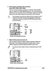
...OnRing output. For external modems, Wake-On-Ring is received through the COM port. ® PRL-DL J1 PRL-DL Wake on the fan connectors! DO NOT place jumper caps on Ring Header ASUS PRL-DL motherboard user guide 2-23 Connect the fan cables to the fan connectors on the motherboard, making ...12V. Lack of sufficient air flow within the system may damage the motherboard components. FAN2 Rotation +12V GND ® PRL-DL FAN1 FAN3 GND +12V Rotation GND +12V Rotation PRL-DL 12-Volt Cooling Fan Power 7. 6. The connector powers up the system when a ringup packet or signal is detected ...
...OnRing output. For external modems, Wake-On-Ring is received through the COM port. ® PRL-DL J1 PRL-DL Wake on the fan connectors! DO NOT place jumper caps on Ring Header ASUS PRL-DL motherboard user guide 2-23 Connect the fan cables to the fan connectors on the motherboard, making ...12V. Lack of sufficient air flow within the system may damage the motherboard components. FAN2 Rotation +12V GND ® PRL-DL FAN1 FAN3 GND +12V Rotation GND +12V Rotation PRL-DL 12-Volt Cooling Fan Power 7. 6. The connector powers up the system when a ringup packet or signal is detected ...
PRL-DL M/B User Guide
Page 51
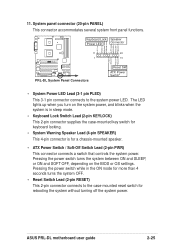
...This 2-pin connector connects to the system power LED. Keyboard Lock Speaker Power LED Connector +5 V PLED Keylock Ground +5V IDELED+ IDELEDSpeaker ® PRL-DL 11 1 PRL-DL System Panel Connectors PWR Ground Reset Ground 20 10 Reset SW ATX Power Switch* • System Power LED Lead (3-1 pin PLED) This 3-1 ... connects a switch that controls the system power. The LED lights up when you turn on the BIOS or OS settings. ASUS PRL-DL motherboard user guide 2-25 11. System panel connector (20-pin PANEL) This connector accommodates several system front panel functions.
...This 2-pin connector connects to the system power LED. Keyboard Lock Speaker Power LED Connector +5 V PLED Keylock Ground +5V IDELED+ IDELEDSpeaker ® PRL-DL 11 1 PRL-DL System Panel Connectors PWR Ground Reset Ground 20 10 Reset SW ATX Power Switch* • System Power LED Lead (3-1 pin PLED) This 3-1 ... connects a switch that controls the system power. The LED lights up when you turn on the BIOS or OS settings. ASUS PRL-DL motherboard user guide 2-25 11. System panel connector (20-pin PANEL) This connector accommodates several system front panel functions.


