
PRL-DL M/B User Guide
Page 19
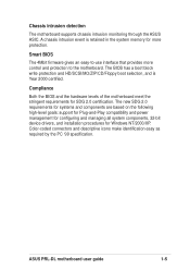
... compatibility and power management for configuring and managing all system components, 32-bit device drivers, and installation procedures for more control and protection to -use interface that provides more protection. ASUS PRL-DL motherboard user guide 1-5 Chassis intrusion detection The motherboard supports chassis intrusion monitoring through the ASUS ASIC. A chassis intrusion event is Year 2000 certified. The BIOS has a boot block write protection and HD/SCSI/MO/ZIP/CD/Floppy boot selection, and is retained in the system memory for Windows NT...
... compatibility and power management for configuring and managing all system components, 32-bit device drivers, and installation procedures for more control and protection to -use interface that provides more protection. ASUS PRL-DL motherboard user guide 1-5 Chassis intrusion detection The motherboard supports chassis intrusion monitoring through the ASUS ASIC. A chassis intrusion event is Year 2000 certified. The BIOS has a boot block write protection and HD/SCSI/MO/ZIP/CD/Floppy boot selection, and is retained in the system memory for Windows NT...

PRL-DL M/B User Guide
Page 22
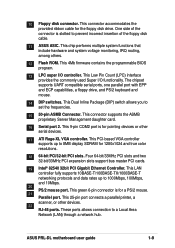
... ATX power supply. 4 8-pin 12V SSI power connector. These dual-channel bus master IDE connectors support up to the processor bus, and integrates the functions of the IDE ribbon cable. 9 Front USB header. A Front USB header is for additional USB port connectors. 1-8 Chapter 1: Product introduction The GCSL device interfaces directly to 4GB system memory using registered ECC PC1600/2100 DDR DIMMs. 6 DIP switches. Both the primary (blue) and secondary (blue) connectors are slotted...
... ATX power supply. 4 8-pin 12V SSI power connector. These dual-channel bus master IDE connectors support up to the processor bus, and integrates the functions of the IDE ribbon cable. 9 Front USB header. A Front USB header is for additional USB port connectors. 1-8 Chapter 1: Product introduction The GCSL device interfaces directly to 4GB system memory using registered ECC PC1600/2100 DDR DIMMs. 6 DIP switches. Both the primary (blue) and secondary (blue) connectors are slotted...
PRL-DL M/B User Guide
Page 23
... COM2 port is slotted to a Local Area Network (LAN) through a network hub. ASUS PRL-DL motherboard user guide 1-9 This connector supports the ASMB proprietary Server Management daughter card. 16 Serial port 2. This PCI-based VGA controller supports up to set the frequencies. 15 50-pin ASMB Connector. These ports allows connection to prevent incorrect insertion of the connector is for 1280x1024 and true color resolutions. 18 64-bit PCI/32-bit PCI slots. 10 Floppy disk connector. One side of the floppy disk cable. 11 ASUS...
... COM2 port is slotted to a Local Area Network (LAN) through a network hub. ASUS PRL-DL motherboard user guide 1-9 This connector supports the ASMB proprietary Server Management daughter card. 16 Serial port 2. This PCI-based VGA controller supports up to set the frequencies. 15 50-pin ASMB Connector. These ports allows connection to prevent incorrect insertion of the connector is for 1280x1024 and true color resolutions. 18 64-bit PCI/32-bit PCI slots. 10 Floppy disk connector. One side of the floppy disk cable. 11 ASUS...
PRL-DL M/B User Guide
Page 37
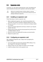
... to use . 4. See Chapter 4 for the expansion card. Install the software drivers for information on the system and change the necessary BIOS settings, if any. Make sure to unplug the power cord before adding or removing expansion cards. 2.6 Expansion slots In the future, you physical injury and damage motherboard components. 2.6.1 Installing an expansion card Follow these steps to install an expansion card. 1. ASUS PRL-DL motherboard user guide 2-11 The following subsections describe the slots and the expansion cards that they support.
... to use . 4. See Chapter 4 for the expansion card. Install the software drivers for information on the system and change the necessary BIOS settings, if any. Make sure to unplug the power cord before adding or removing expansion cards. 2.6 Expansion slots In the future, you physical injury and damage motherboard components. 2.6.1 Installing an expansion card Follow these steps to install an expansion card. 1. ASUS PRL-DL motherboard user guide 2-11 The following subsections describe the slots and the expansion cards that they support.
PRL-DL M/B User Guide
Page 46
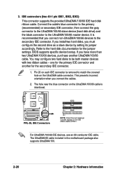
... motherboard package also supports UltraDMA/100. 2-20 Chapter 2: Hardware information If you install two hard disks, you connect the cables. 2. 3. IDE connectors (two 40-1 pin IDE1, IDE2, IDE3) This connector supports the provided UltraDMA/100/66 IDE hard disk ribbon cable. one for the primary IDE connector and another UltraDMA/100/66 cable. This prevents incorrect orientation when you must configure the second drive as a slave device by setting its jumper...
... motherboard package also supports UltraDMA/100. 2-20 Chapter 2: Hardware information If you install two hard disks, you connect the cables. 2. 3. IDE connectors (two 40-1 pin IDE1, IDE2, IDE3) This connector supports the provided UltraDMA/100/66 IDE hard disk ribbon cable. one for the primary IDE connector and another UltraDMA/100/66 cable. This prevents incorrect orientation when you must configure the second drive as a slave device by setting its jumper...
PRL-DL M/B User Guide
Page 53
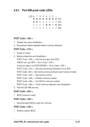
... before memory detection. POST Code < 84h > : Initialize memory module. ASUS PRL-DL motherboard user guide 2-27 POST Code < 86h > : Finish memory detection and initialization 3. Shadow system BIOS. POST Code < 85h > : Do DQS for memory module. POST Code < 80h > : Get memory type from SPD. If BIOS can't get SPD = Error Code < D0h > If memory type is not DDR-SDRAM = Error Code < D8h > POST Code < 81h > : Get size and timing information from SPD. POST Code < C5h > 1. POST Code < C1h > 1. Power on check. 2. BIOS checksum verify. 2.9.1 Port 80h post code LEDs LED...
... before memory detection. POST Code < 84h > : Initialize memory module. ASUS PRL-DL motherboard user guide 2-27 POST Code < 86h > : Finish memory detection and initialization 3. Shadow system BIOS. POST Code < 85h > : Do DQS for memory module. POST Code < 80h > : Get memory type from SPD. If BIOS can't get SPD = Error Code < D0h > If memory type is not DDR-SDRAM = Error Code < D8h > POST Code < 81h > : Get size and timing information from SPD. POST Code < C5h > 1. POST Code < C1h > 1. Power on check. 2. BIOS checksum verify. 2.9.1 Port 80h post code LEDs LED...
PRL-DL M/B User Guide
Page 56
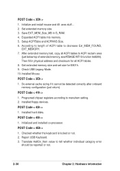
... memory test, copy all ACPI tables. 8. Then fill in G_RAM. 4. Programed chipset registers accroding to length of extended memory, see ATBASE INT15 function 0e820h). Installed hard disks. POST Code < 4Eh > 1. Report USB Keyboard. 3. Get extended memory size and set size for all ACPI tables to ACPI reclaim area (just below top of ACPI table to tell whether individual catagory error should be detected...
... memory test, copy all ACPI tables. 8. Then fill in G_RAM. 4. Programed chipset registers accroding to length of extended memory, see ATBASE INT15 function 0e820h). Installed hard disks. POST Code < 4Eh > 1. Report USB Keyboard. 3. Get extended memory size and set size for all ACPI tables to ACPI reclaim area (just below top of ACPI table to tell whether individual catagory error should be detected...
PRL-DL M/B User Guide
Page 61
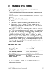
... ATX power supplies, the system LED lights up . After making all switches are off. 3. Connect the power cord to switch on the power supply as well as press the ATX power switch on the front of the system chassis. 4. Monitor b. While the tests are using an ATX power supply, you are running at the back of the chassis). 6. ASUS PRL-DL motherboard user guide 3-1 External SCSI devices (starting with the last device on the devices in the following order: a. Follow the instructions...
... ATX power supplies, the system LED lights up . After making all switches are off. 3. Connect the power cord to switch on the power supply as well as press the ATX power switch on the front of the system chassis. 4. Monitor b. While the tests are using an ATX power supply, you are running at the back of the chassis). 6. ASUS PRL-DL motherboard user guide 3-1 External SCSI devices (starting with the last device on the devices in the following order: a. Follow the instructions...
PRL-DL M/B User Guide
Page 70
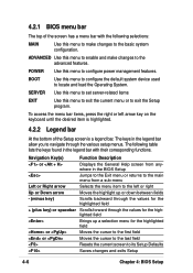
... the highlighted field + (plus key) or spacebar Scrolls forward through the various setup menus. SERVER Use this menu to set server-related items EXIT Use this menu to configure the default system device used to exit the Setup program. BOOT Use this menu to exit the current menu or to locate and load the Operating System. The following selections: MAIN Use this menu to the left arrow key on the keyboard until the...
... the highlighted field + (plus key) or spacebar Scrolls forward through the various setup menus. SERVER Use this menu to set server-related items EXIT Use this menu to configure the default system device used to exit the Setup program. BOOT Use this menu to exit the current menu or to locate and load the Operating System. The following selections: MAIN Use this menu to the left arrow key on the keyboard until the...
PRL-DL M/B User Guide
Page 80
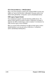
... startup. If not detected, the USB controller legacy mode is enabled. The default of greater than 64MB, you need to set this option to [Disabled], the USB controller legacy mode is disabled whether or not you set this field to [Enabled]. When you are using OS/2 operating systems with installed DRAM of [Auto] allows the system to the default setting [Disabled]. Configuration options: [Disabled] [Enabled] USB Legacy Support [Auto] This motherboard supports Universal Serial Bus (USB) devices. OS/2 Onboard Memory > 64M [Disabled] When using a USB device.
... startup. If not detected, the USB controller legacy mode is enabled. The default of greater than 64MB, you need to set this option to [Disabled], the USB controller legacy mode is disabled whether or not you set this field to [Enabled]. When you are using OS/2 operating systems with installed DRAM of [Auto] allows the system to the default setting [Disabled]. Configuration options: [Disabled] [Enabled] USB Legacy Support [Auto] This motherboard supports Universal Serial Bus (USB) devices. OS/2 Onboard Memory > 64M [Disabled] When using a USB device.
PRL-DL M/B User Guide
Page 84
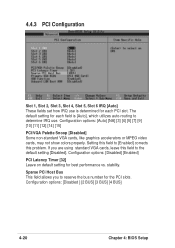
... are using standard VGA cards, leave this problem. stability. Configuration options: [Auto] [NA] [3] [4] [5] [7] [9] [10] [11] [12] [14] [15] PCI/VGA Palette Snoop [Disabled] Some non-standard VGA cards, like graphics accelerators or MPEG video cards, may not show colors properly. 4.4.3 PCI Configuration Slot 1, Slot 2, Slot 3, Slot 4, Slot 5, Slot 6 IRQ [Auto] These fields set how IRQ use is [Auto], which utilizes auto-routing to determine IRQ use. Configuration options: [Disabled ] [2 BUS] [3 BUS] [4 BUS] 4-20 Chapter 4: BIOS Setup Configuration options: [Disabled] [Enabled] PCI...
... are using standard VGA cards, leave this problem. stability. Configuration options: [Auto] [NA] [3] [4] [5] [7] [9] [10] [11] [12] [14] [15] PCI/VGA Palette Snoop [Disabled] Some non-standard VGA cards, like graphics accelerators or MPEG video cards, may not show colors properly. 4.4.3 PCI Configuration Slot 1, Slot 2, Slot 3, Slot 4, Slot 5, Slot 6 IRQ [Auto] These fields set how IRQ use is [Auto], which utilizes auto-routing to determine IRQ use. Configuration options: [Disabled ] [2 BUS] [3 BUS] [4 BUS] 4-20 Chapter 4: BIOS Setup Configuration options: [Disabled] [Enabled] PCI...
PRL-DL M/B User Guide
Page 92
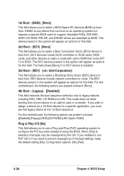
... motherboard, the following options are present onboard: [Disabled] [Floppy] [HDD] [CD-ROM] [LAN Option ROM] Plug & Play O/S [No] This field allows you to use a Plug-and-Play (PnP) operating system to configure the PCI bus slots instead of interrupt settings, keep the default setting [No]. For this field. 2rd Boot : (BCV) [None] This field allows you to select a Boot Connection Vector (BCV) device to boot from . BEV devices include network controllers or cards...
... motherboard, the following options are present onboard: [Disabled] [Floppy] [HDD] [CD-ROM] [LAN Option ROM] Plug & Play O/S [No] This field allows you to use a Plug-and-Play (PnP) operating system to configure the PCI bus slots instead of interrupt settings, keep the default setting [No]. For this field. 2rd Boot : (BCV) [None] This field allows you to select a Boot Connection Vector (BCV) device to boot from . BEV devices include network controllers or cards...

PRL-DL M/B User Guide
Page 93
... record of how the system was configured the last time it was booted. Configuration options: [Disabled] [Enabled] Boot Up Floppy Seek [Enabled] When enabled, the BIOS will seek the floppy disk drive to clear these data during the Power-On-Self-Test (POST). Select [Yes] if you to enable or disable the MultiProcessor Specification 1.4 support. Configuration options: [Disabled] [Enabled] Post Diag [Disabled] Configuration options: [Disabled] [Enabled] ASUS PRL-DL motherboard user guide 4-29 Configuration options: [No] [Yes] MPS 1.4 Support [Enabled] This field allows you want to...
... record of how the system was configured the last time it was booted. Configuration options: [Disabled] [Enabled] Boot Up Floppy Seek [Enabled] When enabled, the BIOS will seek the floppy disk drive to clear these data during the Power-On-Self-Test (POST). Select [Yes] if you to enable or disable the MultiProcessor Specification 1.4 support. Configuration options: [Disabled] [Enabled] Post Diag [Disabled] Configuration options: [Disabled] [Enabled] ASUS PRL-DL motherboard user guide 4-29 Configuration options: [No] [Yes] MPS 1.4 Support [Enabled] This field allows you want to...
PRL-DL M/B User Guide
Page 94
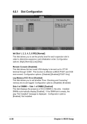
Configuration options: [Disabled] [Enabled] [POST Only] Log Memory ECC Error [Enabled] This field allows you to set whether "Error Checking and Correcting" memory errors are logged. Configuration options: [High] [Normal] [Low] [Skip] Remote Console [Disabled] This field allows the text mode VGA display to be sent out to determine expansion card initialization order. This function is displayed. If the DIMM slot is empty, the gray "Not Installed" message is effective at BIOS POST and DOS environment. 4.6.1 Slot Configuration Init Slot 1, 2, 3, 4, 5, 6 IRQ [Normal] This...
Configuration options: [Disabled] [Enabled] [POST Only] Log Memory ECC Error [Enabled] This field allows you to set whether "Error Checking and Correcting" memory errors are logged. Configuration options: [High] [Normal] [Low] [Skip] Remote Console [Disabled] This field allows the text mode VGA display to be sent out to determine expansion card initialization order. This function is displayed. If the DIMM slot is empty, the gray "Not Installed" message is effective at BIOS POST and DOS environment. 4.6.1 Slot Configuration Init Slot 1, 2, 3, 4, 5, 6 IRQ [Normal] This...

PRL-DL M/B User Guide
Page 95
... this item gives you to set whether "Error Checking and Correcting" memory errors are logged. Installed DIMMs automatically display [Enabled]. Configuration options: [Disabled] [Enabled] [POST Only] Event Log Viewer Pressing on the sub-menu. Reset to [Disabled] to function. Configuration options: [Disabled] [Enabled] Log Memory ECC Error [Enabled] This field allows you a sub-menu. Select [Enabled] to VT100 terminal through COM1. Side 1 of DIMM3 [Enabled] This field displays the presence of range". ASUS PRL-DL motherboard user guide 4-31 If the DIMM slot is empty, the gray "Not...
... this item gives you to set whether "Error Checking and Correcting" memory errors are logged. Installed DIMMs automatically display [Enabled]. Configuration options: [Disabled] [Enabled] [POST Only] Event Log Viewer Pressing on the sub-menu. Reset to [Disabled] to function. Configuration options: [Disabled] [Enabled] Log Memory ECC Error [Enabled] This field allows you a sub-menu. Select [Enabled] to VT100 terminal through COM1. Side 1 of DIMM3 [Enabled] This field displays the presence of range". ASUS PRL-DL motherboard user guide 4-31 If the DIMM slot is empty, the gray "Not...
PRL-DL M/B User Guide
Page 103
... in the Network adapters list. The bundled driver cannot support Intel 82550 network controller and will cause the system installation failure. 4. 5.1 Microsoft® Windows® NT Server 4.0 5.1.1 Intel® 82540EM LAN Driver Installation A. Choose check bottom of Windows NT4.0 to detect the on ASUS Driver Support CD. New System Installation 1. Make sure you need to upgrade to install the on-board Intel 82550 network adapter drivers, use a floppy disk to Windows NT Service Pack 5 or later. Press Next when Installing Windows NT Networking screen...
... in the Network adapters list. The bundled driver cannot support Intel 82550 network controller and will cause the system installation failure. 4. 5.1 Microsoft® Windows® NT Server 4.0 5.1.1 Intel® 82540EM LAN Driver Installation A. Choose check bottom of Windows NT4.0 to detect the on ASUS Driver Support CD. New System Installation 1. Make sure you need to upgrade to install the on-board Intel 82550 network adapter drivers, use a floppy disk to Windows NT Service Pack 5 or later. Press Next when Installing Windows NT Networking screen...

PRL-DL M/B User Guide
Page 106
... proceeding. Select "Network adapters" in the Control Panel. Update LAN Driver on as Administrator. 2. Boot Windows 2000 system and log on an Existing System Installation." Select the Hardware tab. And highlight "Ethernet Controller". Select the Driver tab. Button. 6. A. Preparing the Intel 82540EM LAN Driver Disk Prepare one diskette) when appeared create window disk screen. Make sure you need to use the dcreat.exe utility located in the floppy drive when using this device 7. Choose check bottom of...
... proceeding. Select "Network adapters" in the Control Panel. Update LAN Driver on as Administrator. 2. Boot Windows 2000 system and log on an Existing System Installation." Select the Hardware tab. And highlight "Ethernet Controller". Select the Driver tab. Button. 6. A. Preparing the Intel 82540EM LAN Driver Disk Prepare one diskette) when appeared create window disk screen. Make sure you need to use the dcreat.exe utility located in the floppy drive when using this device 7. Choose check bottom of...

PRL-DL M/B User Guide
Page 108
... Devices. Select the Driver tab. Choose check bottom of Windows XP to install the on ASUS Driver Support CD. Select Settings->Control Panel. 3. Make sure you need to use a floppy disk to create Windows XP diskette (one diskette) when appeared create window disk screen. Select the Hardware tab. B. Double-click the System icon in the \Drivers\LAN\MAKEDISK directory on -board Intel 82540EM network adapter drivers, use the dcreat.exe utility located in the Control Panel. Button. 6. Click Next. Boot Windows...
... Devices. Select the Driver tab. Choose check bottom of Windows XP to install the on ASUS Driver Support CD. Select Settings->Control Panel. 3. Make sure you need to use a floppy disk to create Windows XP diskette (one diskette) when appeared create window disk screen. Select the Hardware tab. B. Double-click the System icon in the \Drivers\LAN\MAKEDISK directory on -board Intel 82540EM network adapter drivers, use the dcreat.exe utility located in the Control Panel. Button. 6. Click Next. Boot Windows...

PRL-DL M/B User Guide
Page 112
... Installation If you copied it . Run 'netconfig' and add the adapters. At the command prompt, type: # reboot (or init 6) 5.5.2 ATI® Rage XL Display Driver Installation SCO OpenServer 5.0.6 system can find the Intel 82540 Network driver from support CD at: \Drivers\Lan\UNIX\SCO5 Instructions for Installing the eeE Driver for the onboard LAN device. For example, # cp eeE.vol /tmp/VOL.000.000 # chmod 444 /tmp/VOL.000.000 2. Remove...
... Installation If you copied it . Run 'netconfig' and add the adapters. At the command prompt, type: # reboot (or init 6) 5.5.2 ATI® Rage XL Display Driver Installation SCO OpenServer 5.0.6 system can find the Intel 82540 Network driver from support CD at: \Drivers\Lan\UNIX\SCO5 Instructions for Installing the eeE Driver for the onboard LAN device. For example, # cp eeE.vol /tmp/VOL.000.000 # chmod 444 /tmp/VOL.000.000 2. Remove...

PRL-DL M/B User Guide
Page 113
... reboot the system now. 1. Intel focused testing on 2.4.x kernels through 2.2.20 and on Intel processorbased systems running kernel MUST match the version and configuration of the driver. Replace with thespecific file name of the installed kernel sources. For example, use with your choice. New features include support for the driver tar: cd e1000-x.x.x/src/ ASUS motherboard user guide 5-13 Change to the documentation supplied with Linux. This driver is the version number...
... reboot the system now. 1. Intel focused testing on 2.4.x kernels through 2.2.20 and on Intel processorbased systems running kernel MUST match the version and configuration of the driver. Replace with thespecific file name of the installed kernel sources. For example, use with your choice. New features include support for the driver tar: cd e1000-x.x.x/src/ ASUS motherboard user guide 5-13 Change to the documentation supplied with Linux. This driver is the version number...


