

PRL-DL M/B User Guide
Page 13
It includes brief explanations of the special attributes of the PRL-DL motherboard. Chapter 1 This chapter describes the features of the motherboard and the new technology it supports. Product introduction
It includes brief explanations of the special attributes of the PRL-DL motherboard. Chapter 1 This chapter describes the features of the motherboard and the new technology it supports. Product introduction
PRL-DL M/B User Guide
Page 14
Chapter summary 1.1 Welcome 1-1 1.2 Package contents 1-1 1.3 Special features 1-2 1.4 Motherboard overview 1-6 ASUS PRL-DL motherboard
Chapter summary 1.1 Welcome 1-1 1.2 Package contents 1-1 1.3 Special features 1-2 1.4 Motherboard overview 1-6 ASUS PRL-DL motherboard
PRL-DL M/B User Guide
Page 15
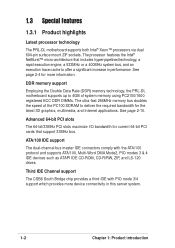
... is damaged or missing, contact your PRL-DL package for the following items. ASUS PRL-DL motherboard Extended ATX form factor: 12 in x 10.5 in (30.48 cm x 26.67 cm) ASUS PRL-DL support CD I/O shield 80-conductor ribbon cable for UltraDMA100/66//33 IDE drives Ribbon cable for buying the ASUS® PRL-DL motherboard! ASUS PRL-DL motherboard user guide 1-1 Thank you start installing...
... is damaged or missing, contact your PRL-DL package for the following items. ASUS PRL-DL motherboard Extended ATX form factor: 12 in x 10.5 in (30.48 cm x 26.67 cm) ASUS PRL-DL support CD I/O shield 80-conductor ribbon cable for UltraDMA100/66//33 IDE drives Ribbon cable for buying the ASUS® PRL-DL motherboard! ASUS PRL-DL motherboard user guide 1-1 Thank you start installing...
PRL-DL M/B User Guide
Page 16
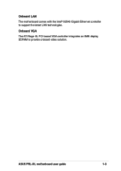
DDR memory support Employing the Double Data Rate (DDR) memory technology, the PRL-DL motherboard supports up to 4GB of system memory using PC2100/1600 registered ECC DDR DIMMs. The ultra-fast 266MHz memory bus doubles the speed of the ... devices such as ATAPI IDE CD-ROM, CD-R/RW, ZIP, and LS-120 drives. See page 2-10. 1.3 Special features 1.3.1 Product highlights Latest processor technology The PRL-DL motherboard supports both Intel® Xeon™ processors via dual 604-pin surface mount ZIF sockets.
DDR memory support Employing the Double Data Rate (DDR) memory technology, the PRL-DL motherboard supports up to 4GB of system memory using PC2100/1600 registered ECC DDR DIMMs. The ultra-fast 266MHz memory bus doubles the speed of the ... devices such as ATAPI IDE CD-ROM, CD-R/RW, ZIP, and LS-120 drives. See page 2-10. 1.3 Special features 1.3.1 Product highlights Latest processor technology The PRL-DL motherboard supports both Intel® Xeon™ processors via dual 604-pin surface mount ZIF sockets.
PRL-DL M/B User Guide
Page 17
Onboard VGA The ATI Rage-XL PCI-based VGA controller integrates an 8MB display SDRAM to support the latest LAN technologies. ASUS PRL-DL motherboard user guide 1-3 Onboard LAN The motherboard comes with the Intel® 82540 Gigabit Ethernet controller to provide onboard video solution.
Onboard VGA The ATI Rage-XL PCI-based VGA controller integrates an 8MB display SDRAM to support the latest LAN technologies. ASUS PRL-DL motherboard user guide 1-3 Onboard LAN The motherboard comes with the Intel® 82540 Gigabit Ethernet controller to provide onboard video solution.
PRL-DL M/B User Guide
Page 19
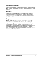
... and power management for configuring and managing all system components, 32-bit device drivers, and installation procedures for SDG 2.0 certification. ASUS PRL-DL motherboard user guide 1-5 The BIOS has a boot block write protection and HD/SCSI/MO/ZIP/CD/Floppy boot selection, and is...requirements for Windows NT/2000/XP. Smart BIOS The 4Mbit firmware gives an easy-to the motherboard. Chassis intrusion detection The motherboard supports chassis intrusion monitoring through the ASUS ASIC. Color-coded connectors and descriptive icons make identification easy as required by the PC '99...
... and power management for configuring and managing all system components, 32-bit device drivers, and installation procedures for SDG 2.0 certification. ASUS PRL-DL motherboard user guide 1-5 The BIOS has a boot block write protection and HD/SCSI/MO/ZIP/CD/Floppy boot selection, and is...requirements for Windows NT/2000/XP. Smart BIOS The 4Mbit firmware gives an easy-to the motherboard. Chassis intrusion detection The motherboard supports chassis intrusion monitoring through the ASUS ASIC. Color-coded connectors and descriptive icons make identification easy as required by the PC '99...

PRL-DL M/B User Guide
Page 20
...Serial port 2 17. ATI Rage-XL VGA controller 18. 64-bit PCI slots (PCI64-1 to Chapter 2 for the specifications of the PRL-DL motherboard as pointed out in the picture on the components. 1-6 Chapter 1: Product introduction USB header 10. LPC Super-I/O controller 14. Intel®...6. USB ports 1 and 2 26. ASUS ASIC 12. Parallel port 22. Floppy connector 11. VGA port 24. Refer to PCI64-4), 32-bit PCI slots (PCI-1 & PCI-2) 19. A sufficient knowledge of the motherboard specifications will also help you install the PRL-DL motherboard, familiarize yourself with its components. 1.4.1...
...Serial port 2 17. ATI Rage-XL VGA controller 18. 64-bit PCI slots (PCI64-1 to Chapter 2 for the specifications of the PRL-DL motherboard as pointed out in the picture on the components. 1-6 Chapter 1: Product introduction USB header 10. LPC Super-I/O controller 14. Intel®...6. USB ports 1 and 2 26. ASUS ASIC 12. Parallel port 22. Floppy connector 11. VGA port 24. Refer to PCI64-4), 32-bit PCI slots (PCI-1 & PCI-2) 19. A sufficient knowledge of the motherboard specifications will also help you install the PRL-DL motherboard, familiarize yourself with its components. 1.4.1...

PRL-DL M/B User Guide
Page 21
1 2 34 5 6 19 7 8 18 17 16 15 14 13 12 11 10 9 20 21 26 25 24 23 22 ASUS PRL-DL motherboard user guide 1-7
1 2 34 5 6 19 7 8 18 17 16 15 14 13 12 11 10 9 20 21 26 25 24 23 22 ASUS PRL-DL motherboard user guide 1-7
PRL-DL M/B User Guide
Page 23
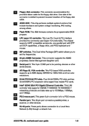
.... This LAN controller fully supports 10BASE-T/100BASE-TX/1000BASE-T networking protocols and data rates up to 8MB display SDRAM for the floppy disk drive. ASUS PRL-DL motherboard user guide 1-9 This 9-pin COM2 port is for a PS/2 mouse. 21 Parallel port. This 25-pin port connects a parallel printer, ...port. This Low Pin Count (LPC) interface provides the commonly used Super I /O controller. One side of the floppy disk cable. 11 ASUS ASIC. This connector accommodates the provided ribbon cable for 1280x1024 and true color resolutions. 18 64-bit PCI/32-bit PCI slots. This ...
.... This LAN controller fully supports 10BASE-T/100BASE-TX/1000BASE-T networking protocols and data rates up to 8MB display SDRAM for the floppy disk drive. ASUS PRL-DL motherboard user guide 1-9 This 9-pin COM2 port is for a PS/2 mouse. 21 Parallel port. This 25-pin port connects a parallel printer, ...port. This Low Pin Count (LPC) interface provides the commonly used Super I /O controller. One side of the floppy disk cable. 11 ASUS ASIC. This connector accommodates the provided ribbon cable for 1280x1024 and true color resolutions. 18 64-bit PCI/32-bit PCI slots. This ...

PRL-DL M/B User Guide
Page 26
Chapter summary 2.1 Motherboard installation 2-1 2.2 Motherboard layout 2-2 2.3 Before you proceed 2-3 2.4 Central Processing Unit (CPU 2-4 2.5 System memory 2-8 2.6 Expansion slots 2-11 2.7 Switches and jumpers 2-14 2.8 Connectors 2-19 ASUS PRL-DL motherboard
Chapter summary 2.1 Motherboard installation 2-1 2.2 Motherboard layout 2-2 2.3 Before you proceed 2-3 2.4 Central Processing Unit (CPU 2-4 2.5 System memory 2-8 2.6 Expansion slots 2-11 2.7 Switches and jumpers 2-14 2.8 Connectors 2-19 ASUS PRL-DL motherboard
PRL-DL M/B User Guide
Page 27
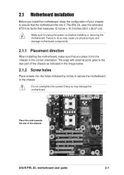
...cord before installing or removing the motherboard. The PRL-DL uses the extended ATX form factor that you place it into the chassis in the image below. 2.1.2 Screw holes Place screws into it. Place this side towards the rear of the chassis ASUS PRL-DL motherboard user guide 2-1 Failure to do... so may damage the motherboard. The edge with external ports goes to the rear part of the chassis as indicated in the correct ...
...cord before installing or removing the motherboard. The PRL-DL uses the extended ATX form factor that you place it into the chassis in the image below. 2.1.2 Screw holes Place screws into it. Place this side towards the rear of the chassis ASUS PRL-DL motherboard user guide 2-1 Failure to do... so may damage the motherboard. The edge with external ports goes to the rear part of the chassis as indicated in the correct ...
PRL-DL M/B User Guide
Page 29
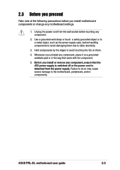
2.3 Before you proceed Take note of the following precautions before you install motherboard components or change any component, place it on them due to static electricity. 3....the power cord from the power supply. Hold components by the edges to avoid damaging them . 4. Before you uninstall any motherboard settings. 1. Failure to do so may cause severe damage to a metal object, such as the power supply case, .... 5. Use a grounded wrist strap or touch a safely grounded object or to the motherboard, peripherals, and/or components. ASUS PRL-DL motherboard user guide 2-3
2.3 Before you proceed Take note of the following precautions before you install motherboard components or change any component, place it on them due to static electricity. 3....the power cord from the power supply. Hold components by the edges to avoid damaging them . 4. Before you uninstall any motherboard settings. 1. Failure to do so may cause severe damage to a metal object, such as the power supply case, .... 5. Use a grounded wrist strap or touch a safely grounded object or to the motherboard, peripherals, and/or components. ASUS PRL-DL motherboard user guide 2-3
PRL-DL M/B User Guide
Page 31
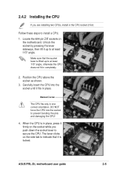
... socket while you are installing two CPUs, install in completely. 2. DO NOT force the CPU into the socket until it fits in one correct orientation. ASUS PRL-DL motherboard user guide 2-5 Make sure that it is in place, press it up to install a CPU. 1. 2.4.2 Installing the CPU If you push down the socket lever... the socket to prevent bending the pins and damaging the CPU! 4. Unlock the socket by pressing the lever sideways, then lift it firmly on the motherboard.
... socket while you are installing two CPUs, install in completely. 2. DO NOT force the CPU into the socket until it fits in one correct orientation. ASUS PRL-DL motherboard user guide 2-5 Make sure that it is in place, press it up to install a CPU. 1. 2.4.2 Installing the CPU If you push down the socket lever... the socket to prevent bending the pins and damaging the CPU! 4. Unlock the socket by pressing the lever sideways, then lift it firmly on the motherboard.
PRL-DL M/B User Guide
Page 33
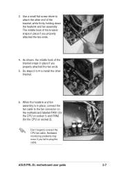
Do steps 2 to 4 to install the other end of the bracket, while firmly holding down the heatsink and fan assembly. ASUS PRL-DL motherboard user guide 2-7 Hardware monitoring problems may occur if you fail to connect the CPU fan cable. When the heatsink and fan assembly is in place ... the bracket snaps in place, connect the fan cable to attach the other bracket. 6. Use a small flat screw driver to the fan connector on the motherboard labeled FAN1 (for the CPU on socket 1) and FAN2 (for the CPU on socket 2).
Do steps 2 to 4 to install the other end of the bracket, while firmly holding down the heatsink and fan assembly. ASUS PRL-DL motherboard user guide 2-7 Hardware monitoring problems may occur if you fail to connect the CPU fan cable. When the heatsink and fan assembly is in place ... the bracket snaps in place, connect the fan cable to attach the other bracket. 6. Use a small flat screw driver to the fan connector on the motherboard labeled FAN1 (for the CPU on socket 1) and FAN2 (for the CPU on socket 2).
PRL-DL M/B User Guide
Page 35
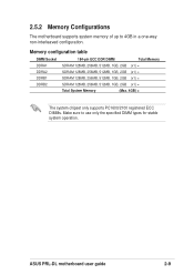
ASUS PRL-DL motherboard user guide 2-9 Memory configuration table DIMM Socket DDRA1 DDRA2 DDRB1 DDRB2 184-pin ECC DDR DIMM Total Memory SDRAM 128MB, 256MB, 512MB, 1GB, 2GB (x1) = ... (Max. 4GB) = The system chipset only supports PC1600/2100 registered ECC DIMMs. Make sure to 4GB in a one-way non-interleaved configuration. 2.5.2 Memory Configurations The motherboard supports system memory of up to use only the specified DIMM types for stable system operation.
ASUS PRL-DL motherboard user guide 2-9 Memory configuration table DIMM Socket DDRA1 DDRA2 DDRB1 DDRB2 184-pin ECC DDR DIMM Total Memory SDRAM 128MB, 256MB, 512MB, 1GB, 2GB (x1) = ... (Max. 4GB) = The system chipset only supports PC1600/2100 registered ECC DIMMs. Make sure to 4GB in a one-way non-interleaved configuration. 2.5.2 Memory Configurations The motherboard supports system memory of up to use only the specified DIMM types for stable system operation.
PRL-DL M/B User Guide
Page 37
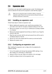
Remove the bracket opposite the slot that you physical injury and damage motherboard components. 2.6.1 Installing an expansion card Follow these steps to install an expansion card. 1. ASUS PRL-DL motherboard user guide 2-11 Align the card connector with the screw you may cause you intend to the tables...the card to install expansion cards. Make sure to the card. Turn on the slot. 5. Remove the system unit cover (if your motherboard is completely seated on the system and change the necessary BIOS settings, if any. 2.6 Expansion slots In the future, you removed earlier....
Remove the bracket opposite the slot that you physical injury and damage motherboard components. 2.6.1 Installing an expansion card Follow these steps to install an expansion card. 1. ASUS PRL-DL motherboard user guide 2-11 Align the card connector with the screw you may cause you intend to the tables...the card to install expansion cards. Make sure to the card. Turn on the slot. 5. Remove the system unit cover (if your motherboard is completely seated on the system and change the necessary BIOS settings, if any. 2.6 Expansion slots In the future, you removed earlier....
PRL-DL M/B User Guide
Page 39
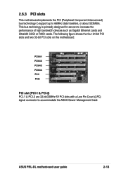
... Management Card. The following figure shows the four 64-bit PCI slots and two 32-bit PCI slots on the motherboard. ASUS PRL-DL motherboard user guide 2-13 PCI64-1 PCI64-2 PCI64-3 PCI64-4 PCI1 PCI2 PCI slot (PCI-1 & PCI-2) PCI-1 & PCI-2 are 32-bit/33MHz 5V PCI slots with a Low Pin ...
... Management Card. The following figure shows the four 64-bit PCI slots and two 32-bit PCI slots on the motherboard. ASUS PRL-DL motherboard user guide 2-13 PCI64-1 PCI64-2 PCI64-3 PCI64-4 PCI1 PCI2 PCI slot (PCI-1 & PCI-2) PCI-1 & PCI-2 are 32-bit/33MHz 5V PCI slots with a Low Pin ...
PRL-DL M/B User Guide
Page 41
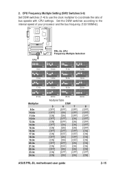
Set the DSW switches according to coordinate the ratio of your processor and the bus frequency (133/100MHz). ® PRL-DL SW2 PRL-DL CPU Frequency Multiple Selection 12345678 12345678 12345678 12345678 ON ON ON ON 8.0x 10.0x 11.0x 12.0x 12345678 12345678 ...ON] [OFF] [OFF] [ON] [ON] [ON] 24.0x 8 [OFF] [OFF] [OFF] [OFF] [OFF] [OFF] [OFF] [ON] [ON] [ON] [ON] [ON] [ON] [ON] [OFF] [ON] ASUS PRL-DL motherboard user guide 2-15 2. CPU Frequency Multiple Setting (SW2 Switches 5-8) Set DSW switches (1-4) to use the clock multiplier to the internal speed of bus speeds with...
Set the DSW switches according to coordinate the ratio of your processor and the bus frequency (133/100MHz). ® PRL-DL SW2 PRL-DL CPU Frequency Multiple Selection 12345678 12345678 12345678 12345678 ON ON ON ON 8.0x 10.0x 11.0x 12.0x 12345678 12345678 ...ON] [OFF] [OFF] [ON] [ON] [ON] 24.0x 8 [OFF] [OFF] [OFF] [OFF] [OFF] [OFF] [OFF] [ON] [ON] [ON] [ON] [ON] [ON] [ON] [OFF] [ON] ASUS PRL-DL motherboard user guide 2-15 2. CPU Frequency Multiple Setting (SW2 Switches 5-8) Set DSW switches (1-4) to use the clock multiplier to the internal speed of bus speeds with...
PRL-DL M/B User Guide
Page 43
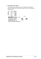
VGA setting (3-pin JVGA1) This jumper is set by default, pins [1-2], to disable the VGA controller. ® PRL-DL JVGA1 12 23 PRL-DL ATI RageXL VGA Setting Enable (Default) Disable ASUS PRL-DL motherboard user guide 2-17 Reset to pins 2-3 to enable the onboard the onboard ATI Rage XL VGA controller. 3.
VGA setting (3-pin JVGA1) This jumper is set by default, pins [1-2], to disable the VGA controller. ® PRL-DL JVGA1 12 23 PRL-DL ATI RageXL VGA Setting Enable (Default) Disable ASUS PRL-DL motherboard user guide 2-17 Reset to pins 2-3 to enable the onboard the onboard ATI Rage XL VGA controller. 3.
PRL-DL M/B User Guide
Page 45
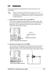
FLOPPY1 ® PRL-DL PIN 1 NOTE: Orient the red markings on the motherboard. Serial port 2 connector (10-1 pin COM2) This connector accommodates a second... the provided floppy drive ribbon cable. Always connect ribbon cables with pin 5 plug). After connecting one end to the motherboard, connect the other end to the floppy drive. (Pin 5 is usually on the side closest to Pin 1 on... into a slot opening at the back of the system chassis. ® PRL-DL COM2 PIN 1 PRL-DL Serial COM2 Connector ASUS PRL-DL motherboard user guide 2-19 PRL-DL Floppy Disk Drive Connector 2.
FLOPPY1 ® PRL-DL PIN 1 NOTE: Orient the red markings on the motherboard. Serial port 2 connector (10-1 pin COM2) This connector accommodates a second... the provided floppy drive ribbon cable. Always connect ribbon cables with pin 5 plug). After connecting one end to the motherboard, connect the other end to the floppy drive. (Pin 5 is usually on the side closest to Pin 1 on... into a slot opening at the back of the system chassis. ® PRL-DL COM2 PIN 1 PRL-DL Serial COM2 Connector ASUS PRL-DL motherboard user guide 2-19 PRL-DL Floppy Disk Drive Connector 2.

