
User Manual
Page 4
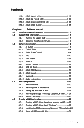
Contents 2.3.8 Front I/O Connector 2-44 2.3.9 Rear panel connection 2-45 2.3.10 Audio I/O connections 2-46 2.3.11 USB BIOS Flashback 2-49 2.4 Starting up for the first time 2-50 2.5 Turning off the computer 2-51 Chapter 3: BIOS ...3.5.5 SATA Configuration 3-33 3.5.6 USB Configuration 3-36 3.5.7 Onboard Devices Configuraton 3-37 3.5.8 APM 3-39 3.6 Monitor menu 3-40 3.7 Boot menu 3-43 3.8 Tools menu 3-44 3.8.1 ASUS EZ Flash 2 Utility 3-45 3.8.2 ASUS DRAM SPD Information 3-45 3.8.3 ASUS O.C. Profile 3-46 3.8.4 ASUS Drive Xpert 3-47 3.9 Exit menu 3-48 3.10 Updating BIOS 3-49 iv
Contents 2.3.8 Front I/O Connector 2-44 2.3.9 Rear panel connection 2-45 2.3.10 Audio I/O connections 2-46 2.3.11 USB BIOS Flashback 2-49 2.4 Starting up for the first time 2-50 2.5 Turning off the computer 2-51 Chapter 3: BIOS ...3.5.5 SATA Configuration 3-33 3.5.6 USB Configuration 3-36 3.5.7 Onboard Devices Configuraton 3-37 3.5.8 APM 3-39 3.6 Monitor menu 3-40 3.7 Boot menu 3-43 3.8 Tools menu 3-44 3.8.1 ASUS EZ Flash 2 Utility 3-45 3.8.2 ASUS DRAM SPD Information 3-45 3.8.3 ASUS O.C. Profile 3-46 3.8.4 ASUS Drive Xpert 3-47 3.9 Exit menu 3-48 3.10 Updating BIOS 3-49 iv
User Manual
Page 5
Contents 3.10.1 3.10.2 3.10.3 3.10.4 ASUS Update utility 3-49 ASUS EZ Flash 2 utility 3-52 ASUS CrashFree BIOS 3 utility 3-53 ASUS BIOS Updater 3-54 Chapter 4: Software support 4.1 Installing an operating system 4-1 4.2 Support DVD information 4-1 4.2.1 ... 4-10 4.3.5 FAN Xpert 4-11 4.3.6 Probe II 4-12 4.3.7 Sensor Recorder 4-13 4.3.8 USB 3.0 Boost 4-14 4.3.9 ASUS SSD Caching 4-15 4.3.10 ASUS Update 4-16 4.3.11 MyLogo2 4-17 4.3.12 Audio configurations 4-19 4.4 RAID configurations 4-20 4.4.1 RAID definitions 4-20 4.4.2 Installing Serial ATA hard disks 4-21 4.4.3 Setting the...
Contents 3.10.1 3.10.2 3.10.3 3.10.4 ASUS Update utility 3-49 ASUS EZ Flash 2 utility 3-52 ASUS CrashFree BIOS 3 utility 3-53 ASUS BIOS Updater 3-54 Chapter 4: Software support 4.1 Installing an operating system 4-1 4.2 Support DVD information 4-1 4.2.1 ... 4-10 4.3.5 FAN Xpert 4-11 4.3.6 Probe II 4-12 4.3.7 Sensor Recorder 4-13 4.3.8 USB 3.0 Boost 4-14 4.3.9 ASUS SSD Caching 4-15 4.3.10 ASUS Update 4-16 4.3.11 MyLogo2 4-17 4.3.12 Audio configurations 4-19 4.4 RAID configurations 4-20 4.4.1 RAID definitions 4-20 4.4.2 Installing Serial ATA hard disks 4-21 4.4.3 Setting the...
User Manual
Page 13
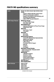
... ASUS DRAM Power - Auto Tuning, TurboV - ASUS SSD Caching - USB BIOS Flashback - ASUS Q-Connector - ASUS EZ Flash 2 Utility ASUS MyLogo 2 Multi-language BIOS ASUS Q-Code ASUS Shield ASUS Q-Slot ASUS Q-Connector ASUS Q-DIMM (continued on the next page) xiii ASUS O.C. DTS Surround Sensation UltraPC II - Supports Jack-Detection, Multi-Streaming, and Front Panel Jack-Retasking - ASUS CrashFree BIOS 3 - P9X79 WS specifications summary Audio ASUS Unique Features ASUS...
... ASUS DRAM Power - Auto Tuning, TurboV - ASUS SSD Caching - USB BIOS Flashback - ASUS Q-Connector - ASUS EZ Flash 2 Utility ASUS MyLogo 2 Multi-language BIOS ASUS Q-Code ASUS Shield ASUS Q-Slot ASUS Q-Connector ASUS Q-DIMM (continued on the next page) xiii ASUS O.C. DTS Surround Sensation UltraPC II - Supports Jack-Detection, Multi-Streaming, and Front Panel Jack-Retasking - ASUS CrashFree BIOS 3 - P9X79 WS specifications summary Audio ASUS Unique Features ASUS...
User Manual
Page 14
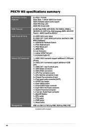
... 1 x PWR button 1 x Reset button WfM 2.0, DMI 2.0, WOL by PME, WOR by PME, PXE (continued on board ASUS SASsaby series Cards support ASUS WS Diag. P9X79 WS specifications summary Workstation Unique Features BIOS Features Back Panel I/O Ports Internal I /O 1 x USB 3.0/2.0 connector support additional 2 USB ports... (4-pin) 1 x Front panel audio connector(AAFP) 1 x S/PDIF Out header 1 x Clear CMOS button 1 x 24-pin EATX Power connector 1 x 8-pin EATX 12V Power connector 1 x System Panel (Q-Connector) 1 x 4-pin EZ_PLUG Power connector 1 x MemOK! LED ASUS WS 3-color LED 64 Mb Flash ROM...
... 1 x PWR button 1 x Reset button WfM 2.0, DMI 2.0, WOL by PME, WOR by PME, PXE (continued on board ASUS SASsaby series Cards support ASUS WS Diag. P9X79 WS specifications summary Workstation Unique Features BIOS Features Back Panel I/O Ports Internal I /O 1 x USB 3.0/2.0 connector support additional 2 USB ports... (4-pin) 1 x Front panel audio connector(AAFP) 1 x S/PDIF Out header 1 x Clear CMOS button 1 x 24-pin EATX Power connector 1 x 8-pin EATX 12V Power connector 1 x System Panel (Q-Connector) 1 x 4-pin EZ_PLUG Power connector 1 x MemOK! LED ASUS WS 3-color LED 64 Mb Flash ROM...
User Manual
Page 21
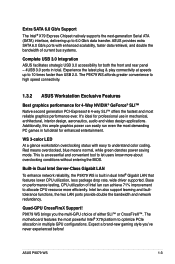
... Server-Class Gigabit LAN To enhance network reliability, the P9X79 WS is an essential and convenient tool to allocate CPU resource more about overclocking conditions without entering the BIOS. ASUS P9X79 WS 1-3 Intel lan also support teaming and faulttolerance functions, ... most powerful Intel® X79 platform to high speed connectivity. 1.3.2 ASUS Workstation Exclusive Features Best graphics performance for professional use in mechanical, architectural, interior design, aeronautics, audio and video design applications. Base on performance testing, CPU utilization of current...
... Server-Class Gigabit LAN To enhance network reliability, the P9X79 WS is an essential and convenient tool to allocate CPU resource more about overclocking conditions without entering the BIOS. ASUS P9X79 WS 1-3 Intel lan also support teaming and faulttolerance functions, ... most powerful Intel® X79 platform to high speed connectivity. 1.3.2 ASUS Workstation Exclusive Features Best graphics performance for professional use in mechanical, architectural, interior design, aeronautics, audio and video design applications. Base on performance testing, CPU utilization of current...

User Manual
Page 26
.... DTS Connect To get the most popular PC audio setups - Consumers can then connect their PC to a home theater system.DTS Interactive is European Union's Energy-related Products (ErP) ready, and ErP requires products to meet certain energy efficiency requirement in line with ASUS vision of creating environmentfriendly and energy-efficient products...
.... DTS Connect To get the most popular PC audio setups - Consumers can then connect their PC to a home theater system.DTS Interactive is European Union's Energy-related Products (ErP) ready, and ErP requires products to meet certain energy efficiency requirement in line with ASUS vision of creating environmentfriendly and energy-efficient products...
User Manual
Page 31
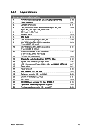
...;A�F�A�N�_�S��E�L�) 14. Front panel audio connector (10-1 pin AAFP) Page 2-32 2-5 2-4 2-29 2-33 2-13 2-10 2-22 2-23 2-24 2-25 2-14 2-22 2-34 2-27 2-12 2-26 2-25 2-30 2-21 2-10 2-28 2-28 2-30 ASUS P9X79 WS 2-3 Intel® X79 Serial ATA 3.0 Gb/s connectors (7-pin SATA3G_3-6 [blue]) 11...
...;A�F�A�N�_�S��E�L�) 14. Front panel audio connector (10-1 pin AAFP) Page 2-32 2-5 2-4 2-29 2-33 2-13 2-10 2-22 2-23 2-24 2-25 2-14 2-22 2-34 2-27 2-12 2-26 2-25 2-30 2-21 2-10 2-28 2-28 2-30 ASUS P9X79 WS 2-3 Intel® X79 Serial ATA 3.0 Gb/s connectors (7-pin SATA3G_3-6 [blue]) 11...

User Manual
Page 36
PCIEx16_5 shared - - - - - - - PCIEx16_6 shared - - - - - - - Asmedia USB3.0-1 shared - - - - - - - LAN1 (82579V) - - SATA Controller 1 - - shared USB 2.0 Controller 2 - - - - - - - shared HD Audio - - - - - - Marvell9128 shared - - - - - - - shared - - - USB 2.0 Controller 1 - - - - - - - Asmedia USB3.0-2 - PCIEx16_4 shared - - - - - - - VIA1394 - shared - - - - - Standard Interrupt assignments IRQ Priority Standard function 0 1 System Timer 1 2 Keyboard Controller 2 - ...
PCIEx16_5 shared - - - - - - - PCIEx16_6 shared - - - - - - - Asmedia USB3.0-1 shared - - - - - - - LAN1 (82579V) - - SATA Controller 1 - - shared USB 2.0 Controller 2 - - - - - - - shared HD Audio - - - - - - Marvell9128 shared - - - - - - - shared - - - USB 2.0 Controller 1 - - - - - - - Asmedia USB3.0-2 - PCIEx16_4 shared - - - - - - - VIA1394 - shared - - - - - Standard Interrupt assignments IRQ Priority Standard function 0 1 System Timer 1 2 Keyboard Controller 2 - ...

User Manual
Page 56
... purchased separately. 2-28 Chapter 2: Hardware information Connect the IEEE 1394a module cable to this connector, then install the module to the IEEE 1394a connector. 6. Digital audio connector (4-1 pin SPDIF_OUT) This connector is for an additional Sony/Philips Digital Interface (S/PDIF) port(s). IEEE 1394a port connector (10-1 pin IE1394_2) This connector is...
... purchased separately. 2-28 Chapter 2: Hardware information Connect the IEEE 1394a module cable to this connector, then install the module to the IEEE 1394a connector. 6. Digital audio connector (4-1 pin SPDIF_OUT) This connector is for an additional Sony/Philips Digital Interface (S/PDIF) port(s). IEEE 1394a port connector (10-1 pin IE1394_2) This connector is...

User Manual
Page 58
...pin COM1) This connector is purchased separately. 2-30 Chapter 2: Hardware information if you want to connect an AC'97 front panel audio module to this connector, then install the module to [AC97]. Connect the serial port module cable to this connector, set to [HD];... at the back of the front panel audio I /O module that you connect a high-definition front panel audio module to this connector to avail of the motherboard's high-definition audio capability. • If you want to connect a high-definition front panel audio module to this connector. ® •...
...pin COM1) This connector is purchased separately. 2-30 Chapter 2: Hardware information if you want to connect an AC'97 front panel audio module to this connector, then install the module to [AC97]. Connect the serial port module cable to this connector, set to [HD];... at the back of the front panel audio I /O module that you connect a high-definition front panel audio module to this connector to avail of the motherboard's high-definition audio capability. • If you want to connect a high-definition front panel audio module to this connector. ® •...

User Manual
Page 72
IDE_LED PWR Ground Reset Ground POWER SW RESET SW To install USB Connector To install front panel audio connector AAFP USB The actual location may vary with motherboards. 2-44 Chapter 2: Hardware information 2.3.8 Front I/O Connector To install ASUS Q-Connector 1 2 IDE_LED+ IDE_LED-
IDE_LED PWR Ground Reset Ground POWER SW RESET SW To install USB Connector To install front panel audio connector AAFP USB The actual location may vary with motherboards. 2-44 Chapter 2: Hardware information 2.3.8 Front I/O Connector To install ASUS Q-Connector 1 2 IDE_LED+ IDE_LED-

User Manual
Page 73
PS/2 keyboard port 6. USB 2.0 ports 5 and 6 10. USB 2.0 ports 7 and 8 11. USB 3.0 ports 1 and 2 12. Audio I/O ports** *and **: Refer to the tables on the next page for LAN port and audio port definitions. USB 2.0 ports 1, 2, 3, and 4 7. LAN (RJ-45) port 2** 5. USB BIOS Flashback button 8. IEEE 1394a port 4. ASUS P9X79 WS 2-45 2.3.9 Rear panel connection 1 2 3 4 5 6 7 8 9 10 11 12 Rear panel connectors 1. Optical S/PDIF Out port 9. LAN (RJ-45) port 1* 3. PS/2 mouse port 2.
PS/2 keyboard port 6. USB 2.0 ports 5 and 6 10. USB 2.0 ports 7 and 8 11. USB 3.0 ports 1 and 2 12. Audio I/O ports** *and **: Refer to the tables on the next page for LAN port and audio port definitions. USB 2.0 ports 1, 2, 3, and 4 7. LAN (RJ-45) port 2** 5. USB BIOS Flashback button 8. IEEE 1394a port 4. ASUS P9X79 WS 2-45 2.3.9 Rear panel connection 1 2 3 4 5 6 7 8 9 10 11 12 Rear panel connectors 1. Optical S/PDIF Out port 9. LAN (RJ-45) port 1* 3. PS/2 mouse port 2.

User Manual
Page 74
...Center/Subwoofer Rear Speaker Out - 8-channel Line In Front Speaker Out Mic In Center/Subwoofer Rear Speaker Out Side Speaker Out 2.3.10 Audio I/O connections Audio I/O ports Connect to USB 3.0 ports for faster and better performance for your USB 3.0 devices. * LAN port LED indications Activity ... Data activity Speed LED Status Description OFF 10 Mbps connection ORANGE 100 Mbps connection GREEN 1 Gbps connection ACT/LINK SPEED LED LED LAN port **Audio 2, 4, 6, or 8-channel configuration Port Light Blue Lime Pink Orange Black Gray Headset 2-channel Line In Line Out Mic In - - ...
...Center/Subwoofer Rear Speaker Out - 8-channel Line In Front Speaker Out Mic In Center/Subwoofer Rear Speaker Out Side Speaker Out 2.3.10 Audio I/O connections Audio I/O ports Connect to USB 3.0 ports for faster and better performance for your USB 3.0 devices. * LAN port LED indications Activity ... Data activity Speed LED Status Description OFF 10 Mbps connection ORANGE 100 Mbps connection GREEN 1 Gbps connection ACT/LINK SPEED LED LED LAN port **Audio 2, 4, 6, or 8-channel configuration Port Light Blue Lime Pink Orange Black Gray Headset 2-channel Line In Line Out Mic In - - ...

User Manual
Page 117
... Screen Version 2.10.1208. The following two items appear only when you to set the HD Audio Controller item to [Enabled]. Chapter 3 ASUS P9X79 WS 3-37 Azalia HD Audio [Enabled] [Disabled] Disables the controller. [Enabled] Enables the High Definition Audio Controller. 3.5.7 Onboard Devices Configuraton UEFI BIOS Utility - Front Panel Type [HD] Allows you set the front...
... Screen Version 2.10.1208. The following two items appear only when you to set the HD Audio Controller item to [Enabled]. Chapter 3 ASUS P9X79 WS 3-37 Azalia HD Audio [Enabled] [Disabled] Disables the controller. [Enabled] Enables the High Definition Audio Controller. 3.5.7 Onboard Devices Configuraton UEFI BIOS Utility - Front Panel Type [HD] Allows you set the front...

User Manual
Page 155
... button Minimize button Control settings window Chapter 4 Information button Refer to display the Realtek HD Audio Manager. ASUS P9X79 WS 4-19 Follow the installation wizard to install the Realtek® Audio Driver from the support DVD that came with the audio devices connected) Device advanced settings Information button Exit button Minimize button Control settings Analog and...
... button Minimize button Control settings window Chapter 4 Information button Refer to display the Realtek HD Audio Manager. ASUS P9X79 WS 4-19 Follow the installation wizard to install the Realtek® Audio Driver from the support DVD that came with the audio devices connected) Device advanced settings Information button Exit button Minimize button Control settings Analog and...

User Manual
Page 159
5. Press after completing your selection. 6. Use the up /down arrow key to select the stripe size for the RAID array (for audio and video editing. 7. When the Capacity item is selected, press . The following are typical values: RAID 0: 128KB RAID 10: 64KB RAID 5: 64KB We... a drive, and then press to create this volume? (Y/N): 9. A small triangle marks the selected drive. Are you sure you want to select. Chapter 4 ASUS P9X79 WS 4-23 The available stripe size values range from 4KB to the CREATE VOLUME menu. The default value indicates the maximum allowed capacity. 8. When the Create...
5. Press after completing your selection. 6. Use the up /down arrow key to select the stripe size for the RAID array (for audio and video editing. 7. When the Capacity item is selected, press . The following are typical values: RAID 0: 128KB RAID 10: 64KB RAID 5: 64KB We... a drive, and then press to create this volume? (Y/N): 9. A small triangle marks the selected drive. Are you sure you want to select. Chapter 4 ASUS P9X79 WS 4-23 The available stripe size values range from 4KB to the CREATE VOLUME menu. The default value indicates the maximum allowed capacity. 8. When the Create...

User Manual
Page 162
.... A smaller stripe size is recommended for the RAID array. 5. The new RAID array appears under Virtual Disks, as shown in much smaller size, such as audio, video, and graphics.
.... A smaller stripe size is recommended for the RAID array. 5. The new RAID array appears under Virtual Disks, as shown in much smaller size, such as audio, video, and graphics.

