
P8B75-M LX PLUS User's Manual
Page 1
Motherboard P8B75-M LX PLUS
Motherboard P8B75-M LX PLUS
P8B75-M LX PLUS User's Manual
Page 3
Contents Safety information vi About this guide vi P8B75-M LX PLUS specifications summary viii Product introduction 1.1 Special features 1-1 1.1.1 Product highlights 1-1 1.1.2 ASUS Exclusive features 1-2 1.2 Before you proceed 1-5 1.3 Motherboard overview 1-5 1.3.1 Placement direction 1-5 1.3.2 Screw holes 1-6 1.3.3 Motherboard layout 1-7 1.3.4 Layout contents 1-8 1.4 Central Processing Unit (CPU 1-9 1.4.1 Installing the CPU 1-10 1.4.2 CPU heatsink and fan assembly installation 1-12 1.5 System memory 1-14 1.5.1 Overview 1-14 1.5.2 Memory...
Contents Safety information vi About this guide vi P8B75-M LX PLUS specifications summary viii Product introduction 1.1 Special features 1-1 1.1.1 Product highlights 1-1 1.1.2 ASUS Exclusive features 1-2 1.2 Before you proceed 1-5 1.3 Motherboard overview 1-5 1.3.1 Placement direction 1-5 1.3.2 Screw holes 1-6 1.3.3 Motherboard layout 1-7 1.3.4 Layout contents 1-8 1.4 Central Processing Unit (CPU 1-9 1.4.1 Installing the CPU 1-10 1.4.2 CPU heatsink and fan assembly installation 1-12 1.5 System memory 1-14 1.5.1 Overview 1-14 1.5.2 Memory...
P8B75-M LX PLUS User's Manual
Page 6
... connectors, slots, sockets and circuitry. • Avoid dust, humidity, and temperature extremes. Operation safety • Before installing the motherboard and adding components, carefully read all the manuals that all cables are correctly connected and the power cables are also provided. It...grounding circuit. • Ensure that your area. If you add a device. • Before connecting or removing signal cables from the motherboard, ensure that came with the product, contact a qualified service technician or your retailer. Safety information Electrical safety • To prevent ...
... connectors, slots, sockets and circuitry. • Avoid dust, humidity, and temperature extremes. Operation safety • Before installing the motherboard and adding components, carefully read all the manuals that all cables are correctly connected and the power cables are also provided. It...grounding circuit. • Ensure that your area. If you add a device. • Before connecting or removing signal cables from the motherboard, ensure that came with the product, contact a qualified service technician or your retailer. Safety information Electrical safety • To prevent ...
P8B75-M LX PLUS User's Manual
Page 11
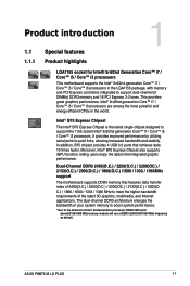
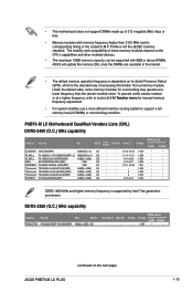
...-Channel DDR3 2400(O.C.) / 2250(O.C.) / 2200(OC.) / 2133(O.C.) / 2000(O.C.) / 1866(O.C.) /1600 / 1333 / 1066MHz support The motherboard supports DDR3 memory that retrieves data 10 times faster. C.) / 1866 / 1600 / 1333 / 1066 MHz to meet the higher bandwidth ...motherboard supports the Intel® 3rd/2nd generation Core™ i7 / Core™ i5 / Core™ i3 processors in the world. This provides great graphics performance. Moreover, Intel® B75 Express Chipset also supports iGPU function, letting users enjoy the latest Intel integrated graphic performance. ASUS P8B75-M LX PLUS...
...-Channel DDR3 2400(O.C.) / 2250(O.C.) / 2200(OC.) / 2133(O.C.) / 2000(O.C.) / 1866(O.C.) /1600 / 1333 / 1066MHz support The motherboard supports DDR3 memory that retrieves data 10 times faster. C.) / 1866 / 1600 / 1333 / 1066 MHz to meet the higher bandwidth ...motherboard supports the Intel® 3rd/2nd generation Core™ i7 / Core™ i5 / Core™ i3 processors in the world. This provides great graphics performance. Moreover, Intel® B75 Express Chipset also supports iGPU function, letting users enjoy the latest Intel integrated graphic performance. ASUS P8B75-M LX PLUS...
P8B75-M LX PLUS User's Manual
Page 12
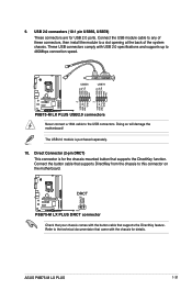
... Shortcut for both the front and rear panel - 4 USB 3.0 ports in 64-bit operating systems. ASUS exclusive interface EZ Mode displays frequently-accessed info. Quick and easy information for sharing UEFI information and troubleshooting - This motherboard delivers up to high speed connectivity. It also natively supports fully-utilized hard drives larger than...
... Shortcut for both the front and rear panel - 4 USB 3.0 ports in 64-bit operating systems. ASUS exclusive interface EZ Mode displays frequently-accessed info. Quick and easy information for sharing UEFI information and troubleshooting - This motherboard delivers up to high speed connectivity. It also natively supports fully-utilized hard drives larger than...
P8B75-M LX PLUS User's Manual
Page 14
... products through the intutive user interface. Network iControl With a one -step setup and an intuitive network bandwidth control center. ASUS Anti-Surge Protection This special design prevents expensive devices and the motherboard from switching power supply (PSU). feature automatically restores CPU default settings when the system crashes due to their default settings...
... products through the intutive user interface. Network iControl With a one -step setup and an intuitive network bandwidth control center. ASUS Anti-Surge Protection This special design prevents expensive devices and the motherboard from switching power supply (PSU). feature automatically restores CPU default settings when the system crashes due to their default settings...
P8B75-M LX PLUS User's Manual
Page 15
...indicated in the correct orientation. Failure to do so may cause severe damage to the motherboard, peripherals, or components. 1.3 Motherboard overview Before you uninstall any component. • Before handling components, use a grounded wrist...motherboard, study the configuration of your chassis to the rear part of the following precautions before you install motherboard components or change any motherboard settings. • Unplug the power cord from the power supply. Unplug the power cord before touching any component, place it into the chassis in the image. ASUS P8B75-M LX PLUS...
...indicated in the correct orientation. Failure to do so may cause severe damage to the motherboard, peripherals, or components. 1.3 Motherboard overview Before you uninstall any component. • Before handling components, use a grounded wrist...motherboard, study the configuration of your chassis to the rear part of the following precautions before you install motherboard components or change any motherboard settings. • Unplug the power cord from the power supply. Unplug the power cord before touching any component, place it into the chassis in the image. ASUS P8B75-M LX PLUS...

P8B75-M LX PLUS User's Manual
Page 16
1.3.2 Screw holes Place six screws into the holes indicated by circles to secure the motherboard to the chassis. Doing so can damage the motherboard. Do not overtighten the screws! Place this side towards the rear of the chassis P8B75-M LX PLUS 1-6 Chapter 1: Product introduction
1.3.2 Screw holes Place six screws into the holes indicated by circles to secure the motherboard to the chassis. Doing so can damage the motherboard. Do not overtighten the screws! Place this side towards the rear of the chassis P8B75-M LX PLUS 1-6 Chapter 1: Product introduction

P8B75-M LX PLUS User's Manual
Page 19
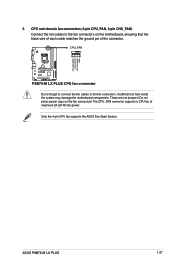
... socket contacts resulting from incorrect CPU installation/removal, or misplacement/loss/incorrect removal of the motherboard, ensure that the PnP cap is shipment/ transit-related. • Keep the cap after installing the motherboard. ASUS P8B75-M LX PLUS 1-9 1.4 Central Processing Unit (CPU) This motherboard comes with the cap on the socket and the socket contacts are not bent.
... socket contacts resulting from incorrect CPU installation/removal, or misplacement/loss/incorrect removal of the motherboard, ensure that the PnP cap is shipment/ transit-related. • Keep the cap after installing the motherboard. ASUS P8B75-M LX PLUS 1-9 1.4 Central Processing Unit (CPU) This motherboard comes with the cap on the socket and the socket contacts are not bent.
P8B75-M LX PLUS User's Manual
Page 24
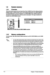
... the OS can be about 3GB or less. For optimal compatibility, we recommend that you want to prevent installation on the motherboard. 1-14 Chapter 1: Product introduction For effective use of memory, we recommend that you are developed for single-channel operation. ... DIMM_B1 P8B75-M LX PLUS P8B75-M LX PLUS 240-pin DDR3 DIMM sockets 1.5.2 Memory configurations You may install 1GB, 2GB, 4GB and 8GB unbuffered non-ECC DDR3 DIMMs into the DIMM sockets. • You may install varying memory sizes in Channel A and Channel B. 1.5 System memory 1.5.1 Overview This motherboard comes with...
... the OS can be about 3GB or less. For optimal compatibility, we recommend that you want to prevent installation on the motherboard. 1-14 Chapter 1: Product introduction For effective use of memory, we recommend that you are developed for single-channel operation. ... DIMM_B1 P8B75-M LX PLUS P8B75-M LX PLUS 240-pin DDR3 DIMM sockets 1.5.2 Memory configurations You may install 1GB, 2GB, 4GB and 8GB unbuffered non-ECC DDR3 DIMMs into the DIMM sockets. • You may install varying memory sizes in Channel A and Channel B. 1.5 System memory 1.5.1 Overview This motherboard comes with...
P8B75-M LX PLUS User's Manual
Page 25
...and its Serial Presence Detect (SPD), which is the standard way of these memory modules depend on the next page) ASUS P8B75-M LX PLUS 1-15 The stability and compatibility of accessing information from a memory module. DIMM socket Size SS/DS Chip Brand Chip ...KINGSTON KHX2250C9D3T1K2/4GX(XMP) 4GB(2 x 2GB) DS Chip Brand Chip NO. - - Profile is supported by Intel® 3rd generation processors. P8B75-M LX Motherboard Qualified Vendors Lists (QVL) DDR3-2400 (O.C.) MHz capability Vendors Part No. Timing Voltage support (optional) 1DIMM 2DIMMs CORSAIR CMGTX8(XMP) 8GB(2GB...
...and its Serial Presence Detect (SPD), which is the standard way of these memory modules depend on the next page) ASUS P8B75-M LX PLUS 1-15 The stability and compatibility of accessing information from a memory module. DIMM socket Size SS/DS Chip Brand Chip ...KINGSTON KHX2250C9D3T1K2/4GX(XMP) 4GB(2 x 2GB) DS Chip Brand Chip NO. - - Profile is supported by Intel® 3rd generation processors. P8B75-M LX Motherboard Qualified Vendors Lists (QVL) DDR3-2400 (O.C.) MHz capability Vendors Part No. Timing Voltage support (optional) 1DIMM 2DIMMs CORSAIR CMGTX8(XMP) 8GB(2GB...

P8B75-M LX PLUS User's Manual
Page 30
... Chapter 1: Product introduction Align a DIMM on the socket such that it flips out 1 with extra force. 1 2. Simultaneously press the retaining clips outward to both the motherboard and the components. 1. Failure to do so can cause severe damage to unlock the DIMM. The DIMM might get damaged when it fits in place...
... Chapter 1: Product introduction Align a DIMM on the socket such that it flips out 1 with extra force. 1 2. Simultaneously press the retaining clips outward to both the motherboard and the components. 1. Failure to do so can cause severe damage to unlock the DIMM. The DIMM might get damaged when it fits in place...
P8B75-M LX PLUS User's Manual
Page 31
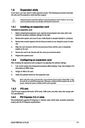
...Expansion slots In the future, you removed earlier. 6. Before installing the expansion card, read the documentation that you physical injury and damage motherboard components. 1.6.1 Installing an expansion card To install an expansion card: 1. Turn on BIOS setup. 2. Assign an IRQ to use ...This motherboard supports PCI Express x1 network cards, SCSI cards, and other cards that they support. Replace the system cover. 1.6.2 Configuring an expansion card After installing the expansion card, configure it and make the necessary hardware settings for the expansion card. ASUS P8B75-M LX PLUS 1-...
...Expansion slots In the future, you removed earlier. 6. Before installing the expansion card, read the documentation that you physical injury and damage motherboard components. 1.6.1 Installing an expansion card To install an expansion card: 1. Turn on BIOS setup. 2. Assign an IRQ to use ...This motherboard supports PCI Express x1 network cards, SCSI cards, and other cards that they support. Replace the system cover. 1.6.2 Configuring an expansion card After installing the expansion card, configure it and make the necessary hardware settings for the expansion card. ASUS P8B75-M LX PLUS 1-...
P8B75-M LX PLUS User's Manual
Page 32
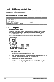
... powers the RAM data in CMOS. Intel PCH SATA controller #1 - - - shared - - - - Keep the cap on pins 2-3 for this motherboard A BC D E F G H Intel PCH SATA controller #0 - - - You can clear the CMOS memory of date, time, and system setup...motherboard supports PCI Express x1 network cards, SCSI cards, and other cards that comply with the PCI Express specifications. Turn OFF the computer and unplug the power cord. 2. Hold down the key during the boot process and enter BIOS setup to pins 2-3. P8B75-M LX PLUS CLRTC 12 23 Normal (Default) Clear RTC P8B75-M LX PLUS...
... powers the RAM data in CMOS. Intel PCH SATA controller #1 - - - shared - - - - Keep the cap on pins 2-3 for this motherboard A BC D E F G H Intel PCH SATA controller #0 - - - You can clear the CMOS memory of date, time, and system setup...motherboard supports PCI Express x1 network cards, SCSI cards, and other cards that comply with the PCI Express specifications. Turn OFF the computer and unplug the power cord. 2. Hold down the key during the boot process and enter BIOS setup to pins 2-3. P8B75-M LX PLUS CLRTC 12 23 Normal (Default) Clear RTC P8B75-M LX PLUS...
P8B75-M LX PLUS User's Manual
Page 35
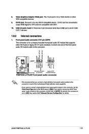
... panel audio I/O module cable to this connector, set the item to CRT and isn't compatible with DVI-I. 10. Connect one end of the motherboard's high-definition audio capability. • If you want to connect a high-definition front panel audio module to [HD]. If you want to...]. This 15-pin port is set to this connector. DVI-D can't be converted to output RGB Signal to [AC97]. Video Graphics Adapter (VGA) port. ASUS P8B75-M LX PLUS 1-25 USB 2.0 ports 3 and 4. AGND NC SENSE1_RETUR SENSE2_RETUR AGND NC NC NC AAFP PIN 1 PIN 1 MIC2 MICPWR Line out_R NC Line out_L PORT1 ...
... panel audio I/O module cable to this connector, set the item to CRT and isn't compatible with DVI-I. 10. Connect one end of the motherboard's high-definition audio capability. • If you want to connect a high-definition front panel audio module to [HD]. If you want to...]. This 15-pin port is set to this connector. DVI-D can't be converted to output RGB Signal to [AC97]. Video Graphics Adapter (VGA) port. ASUS P8B75-M LX PLUS 1-25 USB 2.0 ports 3 and 4. AGND NC SENSE1_RETUR SENSE2_RETUR AGND NC NC NC AAFP PIN 1 PIN 1 MIC2 MICPWR Line out_R NC Line out_L PORT1 ...
P8B75-M LX PLUS User's Manual
Page 37
... 4-pin CPU fan supports the ASUS Fan Xpert feature. ASUS P8B75-M LX PLUS 1-27 CPU FAN PWM CPU FAN IN CPU FAN PWR GND 3. CPU and chassis fan connectors (4-pin CPU_FAN, 4-pin CHA_FAN) Connect the fan cables to the fan connectors. Insufficient air flow inside the system may damage the motherboard components. Do not place jumper...
... 4-pin CPU fan supports the ASUS Fan Xpert feature. ASUS P8B75-M LX PLUS 1-27 CPU FAN PWM CPU FAN IN CPU FAN PWR GND 3. CPU and chassis fan connectors (4-pin CPU_FAN, 4-pin CHA_FAN) Connect the fan cables to the fan connectors. Insufficient air flow inside the system may damage the motherboard components. Do not place jumper...
P8B75-M LX PLUS User's Manual
Page 41
... the system chassis. P8B75-M LX PLUS P8B75-M LX PLUS DRCT connector Check that supports the DirectKey feature. Doing so will damage the motherboard! Refer to the technical documentaion that came with the button cable that your chassis comes with the chassis for USB 2.0 ports. USB 2.0 connectors (10-1 pin USB56, USB78) These connectors are for details. ASUS P8B75-M LX PLUS 1-31 Connect...
... the system chassis. P8B75-M LX PLUS P8B75-M LX PLUS DRCT connector Check that supports the DirectKey feature. Doing so will damage the motherboard! Refer to the technical documentaion that came with the button cable that your chassis comes with the chassis for USB 2.0 ports. USB 2.0 connectors (10-1 pin USB56, USB78) These connectors are for details. ASUS P8B75-M LX PLUS 1-31 Connect...

P8B75-M LX PLUS User's Manual
Page 42
This is ON, in sleep mode, or in any motherboard component. The illustration below shows the location of the onboard LED. 1.9 Onboard LEDs 1. Standby Power LED The motherboard comes with a standby power LED that lights up to indicate that the system is a reminder that you should shut down the system and unplug the power cable before removing or plugging in soft-off mode. SB_PWR P8B75-M LX PLUS ON OFF Standby Power Powered Off P8B75-M LX PLUS Onboard LED 1-32 Chapter 1: Product introduction
This is ON, in sleep mode, or in any motherboard component. The illustration below shows the location of the onboard LED. 1.9 Onboard LEDs 1. Standby Power LED The motherboard comes with a standby power LED that lights up to indicate that the system is a reminder that you should shut down the system and unplug the power cable before removing or plugging in soft-off mode. SB_PWR P8B75-M LX PLUS ON OFF Standby Power Powered Off P8B75-M LX PLUS Onboard LED 1-32 Chapter 1: Product introduction
P8B75-M LX PLUS User's Manual
Page 43
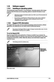
...and system stability. 1.10.2 Support DVD information The Support DVD that comes with the motherboard package contains the drivers, software applications, and utilities that you can install to install ASUS P8B75-M LX PLUS 1-33 If Autorun is for updates. Click an icon to display Support DVD.../motherboard information Click an item to avail all motherboard features. To run the Support DVD Place the Support DVD into...
...and system stability. 1.10.2 Support DVD information The Support DVD that comes with the motherboard package contains the drivers, software applications, and utilities that you can install to install ASUS P8B75-M LX PLUS 1-33 If Autorun is for updates. Click an icon to display Support DVD.../motherboard information Click an item to avail all motherboard features. To run the Support DVD Place the Support DVD into...
P8B75-M LX PLUS User's Manual
Page 45
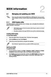
... the popup menu. Updating the BIOS To update the BIOS: 1. BIOS information 2.1 Managing and updating your BIOS 2 Save a copy of the following methods: ASUS P8B75-M LX PLUS 2-1 From the Windows® desktop, click Start > Programs > ASUS > AI Suite II > AI Suite II X.XX.XX to complete the installation. Copy the original motherboard BIOS using this utility.
... the popup menu. Updating the BIOS To update the BIOS: 1. BIOS information 2.1 Managing and updating your BIOS 2 Save a copy of the following methods: ASUS P8B75-M LX PLUS 2-1 From the Windows® desktop, click Start > Programs > ASUS > AI Suite II > AI Suite II X.XX.XX to complete the installation. Copy the original motherboard BIOS using this utility.


