User Manual
Page 6
... ROM Utility 5-25 5.3.1 Creating a RAID set 5-26 5.3.2 Creating a Recovery set 5-27 5.3.3 Deleting a RAID set 5-29 5.3.4 Resetting disks to Non-RAID 5-30 5.3.5 5.3.6 Recovery Volume Options 5-31 Exiting the Intel® Matrix Storage Manager 5-32 5.3.7 Rebuilding the RAID 5-32 5.3.8 Setting the Boot array in the BIOS Setup Utility 5-34 Chapter 6: Driver installation 6.1 RAID driver installation 6-3 6.1.1 Creating a RAID driver disk 6-3 6.1.2 Installing the RAID controller driver 6-6 6.2 Intel® chipset device installation 6-19 6.3 LAN driver installation 6-21 6.4 VGA...
... ROM Utility 5-25 5.3.1 Creating a RAID set 5-26 5.3.2 Creating a Recovery set 5-27 5.3.3 Deleting a RAID set 5-29 5.3.4 Resetting disks to Non-RAID 5-30 5.3.5 5.3.6 Recovery Volume Options 5-31 Exiting the Intel® Matrix Storage Manager 5-32 5.3.7 Rebuilding the RAID 5-32 5.3.8 Setting the Boot array in the BIOS Setup Utility 5-34 Chapter 6: Driver installation 6.1 RAID driver installation 6-3 6.1.1 Creating a RAID driver disk 6-3 6.1.2 Installing the RAID controller driver 6-6 6.2 Intel® chipset device installation 6-19 6.3 LAN driver installation 6-21 6.4 VGA...
User Manual
Page 9
... the switches, jumpers, and connectors on ASUS hardware and software products. These documents are also provided. • Chapter 5: RAID configuration This chapter provides instructions for setting up sequence and ways of the motherboard and the new technologies it supports. • Chapter 2: Hardware information This chapter lists the hardware setup procedures that may include optional documentation, such as warranty flyers, that you need when installing and configuring the motherboard. Optional...
... the switches, jumpers, and connectors on ASUS hardware and software products. These documents are also provided. • Chapter 5: RAID configuration This chapter provides instructions for setting up sequence and ways of the motherboard and the new technologies it supports. • Chapter 2: Hardware information This chapter lists the hardware setup procedures that may include optional documentation, such as warranty flyers, that you need when installing and configuring the motherboard. Optional...
User Manual
Page 35
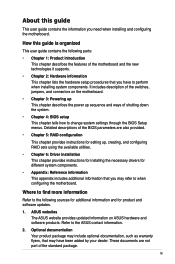
... system and change the necessary BIOS settings, if any. Turn on the slot. 5. Assign an IRQ to unplug the power cord before adding or removing expansion cards. ASUS P7F-E 2-17 Before installing the expansion card, read the documentation that you removed earlier. 6. Align the card connector with the slot and press firmly until the card is already installed in a chassis). 3. Install the software drivers for information on shared slots, ensure that the drivers support "Share...
... system and change the necessary BIOS settings, if any. Turn on the slot. 5. Assign an IRQ to unplug the power cord before adding or removing expansion cards. ASUS P7F-E 2-17 Before installing the expansion card, read the documentation that you removed earlier. 6. Align the card connector with the slot and press firmly until the card is already installed in a chassis). 3. Install the software drivers for information on shared slots, ensure that the drivers support "Share...
User Manual
Page 42
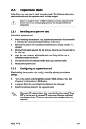
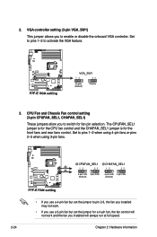
... jumper is for fan pin selection. Set to pins 1-2 when using 4-pin fans or pins 2-3 when using 3-pin fans. • If you use a 4-pin fan but set the jumper to pin 2-3, the fan you installed may not work. • If you use a 3-pin fan but set the jumper for a 4-pin fan, the fan control will not work and the fan you to switch for the front fans and rear fans control. Set to pins 1-2 to enable or disable the onboard VGA controller. CPU Fan and Chassis Fan control setting (3-pin CPUFAN_SEL1, CHAFAN_SEL1) These jumpers allow you installed will always run at full speed...
... jumper is for fan pin selection. Set to pins 1-2 when using 4-pin fans or pins 2-3 when using 3-pin fans. • If you use a 4-pin fan but set the jumper to pin 2-3, the fan you installed may not work. • If you use a 3-pin fan but set the jumper for a 4-pin fan, the fan control will not work and the fan you to switch for the front fans and rear fans control. Set to pins 1-2 to enable or disable the onboard VGA controller. CPU Fan and Chassis Fan control setting (3-pin CPUFAN_SEL1, CHAFAN_SEL1) These jumpers allow you installed will always run at full speed...

User Manual
Page 69
... device supports multi-sector transfer feature. Change Option F1 General Help F10 Save and Exit ESC Exit v02.61 (C)Copyright 1985-2008, American Megatrends, Inc. Configuration options: [Not Installed] [Auto] [CDROM] [ARMD] LBA/Large Mode [Auto] Enables or disables the LBA mode. Configuration options: [Disabled] [Auto] PIO Mode [Auto] Allows you to select the type of IDE/SATA devices. Configuration options: [Auto] [0] [1] [2] [3] [4] ASUS P7F-E 4-11 The BIOS automatically detects the values opposite the dimmed items (Device, Vendor, Size, LBA Mode, Block Mode, PIO Mode...
... device supports multi-sector transfer feature. Change Option F1 General Help F10 Save and Exit ESC Exit v02.61 (C)Copyright 1985-2008, American Megatrends, Inc. Configuration options: [Not Installed] [Auto] [CDROM] [ARMD] LBA/Large Mode [Auto] Enables or disables the LBA mode. Configuration options: [Disabled] [Auto] PIO Mode [Auto] Allows you to select the type of IDE/SATA devices. Configuration options: [Auto] [0] [1] [2] [3] [4] ASUS P7F-E 4-11 The BIOS automatically detects the values opposite the dimmed items (Device, Vendor, Size, LBA Mode, Block Mode, PIO Mode...
User Manual
Page 71
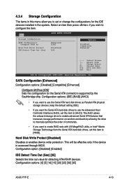
...] [30] [35] ASUS P7F-E 4-13 This will be effective only if the device is accessed through BIOS. Change Option F1 General Help F10 Save and Exit ESC Exit v02.61 (C)Copyright 1985-2009, American Megatrends, Inc. Main BIOS SETUP UTILITY Storage Configuration SATA Configuration [Enhanced] Configure SATA as Parallel ATA physical storage devices, keep the default setting [IDE]. • If you want to configure the item. The AHCI allows the onboard storage driver to [AHCI]. Configuration options: [IDE] [RAID] [AHCI] • If you...
...] [30] [35] ASUS P7F-E 4-13 This will be effective only if the device is accessed through BIOS. Change Option F1 General Help F10 Save and Exit ESC Exit v02.61 (C)Copyright 1985-2009, American Megatrends, Inc. Main BIOS SETUP UTILITY Storage Configuration SATA Configuration [Enhanced] Configure SATA as Parallel ATA physical storage devices, keep the default setting [IDE]. • If you want to configure the item. The AHCI allows the onboard storage driver to [AHCI]. Configuration options: [IDE] [RAID] [AHCI] • If you...
User Manual
Page 74
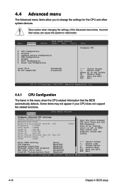
...:Unlocked (Min:09, Max:19) Ratio Actual Value :19 CPUID :106E5 X3440 Sets the ratio between CPU Core Clock and the FSB Frequency. Main Advanced Server BIOS SETUP UTILITY Power Boot Tools CPU Configuration Chipset Onboard Device Configuration USB Configuration PCIPnP ACPI Configuration Event Log Configuration Exit Configure CPU. Note:If an invalid ratio is set in this menu show the CPU-related information that the BIOS automatically detects. Take caution when changing the settings of the Advanced menu items. Incorrect field...
...:Unlocked (Min:09, Max:19) Ratio Actual Value :19 CPUID :106E5 X3440 Sets the ratio between CPU Core Clock and the FSB Frequency. Main Advanced Server BIOS SETUP UTILITY Power Boot Tools CPU Configuration Chipset Onboard Device Configuration USB Configuration PCIPnP ACPI Configuration Event Log Configuration Exit Configure CPU. Note:If an invalid ratio is set in this menu show the CPU-related information that the BIOS automatically detects. Take caution when changing the settings of the Advanced menu items. Incorrect field...
User Manual
Page 80
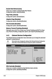
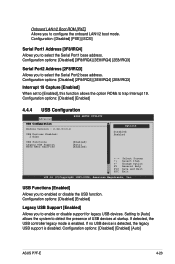
... enable or disable the High Definition Audio controller. HDA Controller [Enabled] Allows you to Open Loop Thermal Throttling. Configuration options: [CLTT] [OLTT] [Disabled] [Auto] 4.4.3 Onboard Devices Configuration The Onboard Devices Configuration menu items allow you to malfunction. Advanced BIOS SETUP UTILITY Onboard Devices Configuration HDA Controller OnBoard LAN1 Boot ROM OnBoard LAN2 Boot ROM Serial Port1 Address Serial Port2 Address Interrupt 19 Capture [Enabled] [PXE] [PXE] [3F8/IRQ4] [2F8/IRQ3] [Enabled] Options Enabled Disabled ←→ Select Screen...
... enable or disable the High Definition Audio controller. HDA Controller [Enabled] Allows you to Open Loop Thermal Throttling. Configuration options: [CLTT] [OLTT] [Disabled] [Auto] 4.4.3 Onboard Devices Configuration The Onboard Devices Configuration menu items allow you to malfunction. Advanced BIOS SETUP UTILITY Onboard Devices Configuration HDA Controller OnBoard LAN1 Boot ROM OnBoard LAN2 Boot ROM Serial Port1 Address Serial Port2 Address Interrupt 19 Capture [Enabled] [PXE] [PXE] [3F8/IRQ4] [2F8/IRQ3] [Enabled] Options Enabled Disabled ←→ Select Screen...
User Manual
Page 81
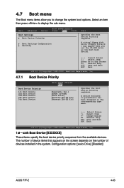
...[Enabled] 4.4.4 USB Configuration Advanced BIOS SETUP UTILITY USB Configuration Module Version - 2.24.3-13.4 USB Devices Enabled: 2 Hubs USB Functions [Enabled] Legacy USB Support [Auto] BIOS EHCI Hand-off [Enabled] Options Disabled Enabled +F1 F10 ESC Select Screen Select Item Change Option General Help Save and Exit Exit v02.61 (C)Copyright 1985-2008, American Megatrends, Inc. If detected, the USB controller legacy mode is disabled. Configuration: [Disabled] [PXE] [iSCSI] Serial Port1 Address [3F8/IRQ4] Allows you to enable or disable support for legacy USB devices...
...[Enabled] 4.4.4 USB Configuration Advanced BIOS SETUP UTILITY USB Configuration Module Version - 2.24.3-13.4 USB Devices Enabled: 2 Hubs USB Functions [Enabled] Legacy USB Support [Auto] BIOS EHCI Hand-off [Enabled] Options Disabled Enabled +F1 F10 ESC Select Screen Select Item Change Option General Help Save and Exit Exit v02.61 (C)Copyright 1985-2008, American Megatrends, Inc. If detected, the USB controller legacy mode is disabled. Configuration: [Disabled] [PXE] [iSCSI] Serial Port1 Address [3F8/IRQ4] Allows you to enable or disable support for legacy USB devices...

User Manual
Page 86
Server BIOS SETUP UTILITY Configure Remote Access type and parameters Remote Access [Enabled] Serial port number Base Address, IRQ Serial Port Mode Flow Control Redirection After BIOS POST Terminal Type [COM2] [2F8h, 3] [57600 8,n,1] [Hardware] [Disabled] [VT-UTF8] Select Remote Access type. +F1 F10 ESC Select Screen Select Item Change Option General Help Save and Exit Exit v02.61 (C)Copyright 1985-2009, American Megatrends, Inc. Remote Access [Enabled] Enables or disables the remote access feature. Select an item then press...
Server BIOS SETUP UTILITY Configure Remote Access type and parameters Remote Access [Enabled] Serial port number Base Address, IRQ Serial Port Mode Flow Control Redirection After BIOS POST Terminal Type [COM2] [2F8h, 3] [57600 8,n,1] [Hardware] [Disabled] [VT-UTF8] Select Remote Access type. +F1 F10 ESC Select Screen Select Item Change Option General Help Save and Exit Exit v02.61 (C)Copyright 1985-2009, American Megatrends, Inc. Remote Access [Enabled] Enables or disables the remote access feature. Select an item then press...
User Manual
Page 91
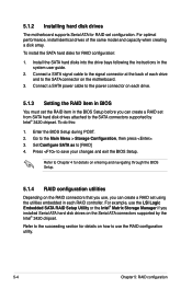
... to change the system boot options. 4.7 Boot menu The Boot menu items allow you set the CD-ROM drive as the first boot device. ←→ Select Screen ↑↓ Select Item Enter Go to Sub Screen F1 General Help F10 Save and Exit ESC Exit v02.61 (C)Copyright 1985-2009, American Megatrends, Inc. 4.7.1 Boot Device Priority BIOS SETUP UTILITY Boot Boot Device Priority 1st Boot Device 2nd Boot Device 3rd Boot Device 4th Boot Device 5th Boot Device [Removable Dev.] [ATAPI CD-ROM] [Hard Drive] [Network:IBA...
... to change the system boot options. 4.7 Boot menu The Boot menu items allow you set the CD-ROM drive as the first boot device. ←→ Select Screen ↑↓ Select Item Enter Go to Sub Screen F1 General Help F10 Save and Exit ESC Exit v02.61 (C)Copyright 1985-2009, American Megatrends, Inc. 4.7.1 Boot Device Priority BIOS SETUP UTILITY Boot Boot Device Priority 1st Boot Device 2nd Boot Device 3rd Boot Device 4th Boot Device 5th Boot Device [Removable Dev.] [ATAPI CD-ROM] [Hard Drive] [Network:IBA...

User Manual
Page 93
... clear the supervisor password, select the Change Supervisor Password then press . If you can clear it by erasing the CMOS Real Time Clock (RTC) RAM. Confirm the password when prompted. Select the Change Supervisor Password item and press . 2. ASUS P7F-E 4-35 The Supervisor Password item on how to change the supervisor password, follow the same steps as in setting a user password. BIOS SETUP UTILITY Boot Security Settings Supervisor Password : Not Installed User Password : Not Installed to erase the RTC RAM...
... clear the supervisor password, select the Change Supervisor Password then press . If you can clear it by erasing the CMOS Real Time Clock (RTC) RAM. Confirm the password when prompted. Select the Change Supervisor Password item and press . 2. ASUS P7F-E 4-35 The Supervisor Password item on how to change the supervisor password, follow the same steps as in setting a user password. BIOS SETUP UTILITY Boot Security Settings Supervisor Password : Not Installed User Password : Not Installed to erase the RTC RAM...
User Manual
Page 94
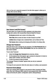
Main Advanced BIOS SETUP UTILITY Server Power Boot Tools Exit Supervisor Password : Installed User Password : Not Installed Change Supervisor Password User Access Level Change User Password Password Check [Full Access] [Setup] to change to any field. Select the Change User Password item and press . 2. On the password box that appears, type a password composed of the screen shows the default Not Installed. Password Check [Setup] When set to change the user password, follow the same steps as Date and Time. View Only allows access but does not allow you to...
Main Advanced BIOS SETUP UTILITY Server Power Boot Tools Exit Supervisor Password : Installed User Password : Not Installed Change Supervisor Password User Access Level Change User Password Password Check [Full Access] [Setup] to change to any field. Select the Change User Password item and press . 2. On the password box that appears, type a password composed of the screen shows the default Not Installed. Password Check [Setup] When set to change the user password, follow the same steps as Date and Time. View Only allows access but does not allow you to...
User Manual
Page 100
... the signal connector at the back of the same model and capacity when creating a disk array. Connect a SATA power cable to the power connector on each drive. 5.1.3 Setting the RAID item in BIOS You must set the RAID item in the BIOS Setup before you can create a RAID set using the utilities embedded in the system user guide. 2. For example, use the RAID configuration utility. 5-4 Chapter 5: RAID configuration 5.1.2 Installing hard disk drives The motherboard supports Serial ATA for RAID configuration: 1. For optimal performance, install identical drives of each RAID controller.
... the signal connector at the back of the same model and capacity when creating a disk array. Connect a SATA power cable to the power connector on each drive. 5.1.3 Setting the RAID item in BIOS You must set the RAID item in the BIOS Setup before you can create a RAID set using the utilities embedded in the system user guide. 2. For example, use the RAID configuration utility. 5-4 Chapter 5: RAID configuration 5.1.2 Installing hard disk drives The motherboard supports Serial ATA for RAID configuration: 1. For optimal performance, install identical drives of each RAID controller.
User Manual
Page 101
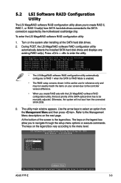
... installed SATA hard disk drives and displays any existing RAID set (s) from SATA hard disk drives connected to the SATA connectors supported by the motherboard southbridge chip. LSI MegaRAID Software RAID BIOS Version A.09 04300936R LSI SATA RAID Found at PCI Bus No: Dev No:1F Device present at Port 0 ST3160812AS 152114MB Device present at Port 1 ST3160812AS 152114MB Device present at Port 2 ST3160812AS 152114MB Device present at Port 3 ST3160812AS 152114MB Press Ctrl-M or Enter to run LSI Software RAID Setup Utility. • The LSI MegaRAID software RAID configuration utility...
... installed SATA hard disk drives and displays any existing RAID set (s) from SATA hard disk drives connected to the SATA connectors supported by the motherboard southbridge chip. LSI MegaRAID Software RAID BIOS Version A.09 04300936R LSI SATA RAID Found at PCI Bus No: Dev No:1F Device present at Port 0 ST3160812AS 152114MB Device present at Port 1 ST3160812AS 152114MB Device present at Port 2 ST3160812AS 152114MB Device present at Port 3 ST3160812AS 152114MB Press Ctrl-M or Enter to run LSI Software RAID Setup Utility. • The LSI MegaRAID software RAID configuration utility...
User Manual
Page 133
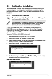
... in a RAID set. Create Driver Diskette Menu PCH INTEL RAID Driver PCH LSI RAID Driver FreeDOS command prompt 5. If you have to boot from the connected SATA ODD. Select the optical drive as the first boot priority to use a USB floppy drive when creating a SATA RAID driver disk. PCH INTEL RAID Driver PCH INTEL RAID Driver Windows 32 bit(also support AHCI) Windows 64 bit(also support AHCI) Back Exit ASUS P7F-E 6-3 Restart the computer, and then enter the BIOS Setup. 3. A floppy disk with the LSI Software RAID configuration utility, the boot priority of RAID driver disk you...
... in a RAID set. Create Driver Diskette Menu PCH INTEL RAID Driver PCH LSI RAID Driver FreeDOS command prompt 5. If you have to boot from the connected SATA ODD. Select the optical drive as the first boot priority to use a USB floppy drive when creating a SATA RAID driver disk. PCH INTEL RAID Driver PCH INTEL RAID Driver Windows 32 bit(also support AHCI) Windows 64 bit(also support AHCI) Back Exit ASUS P7F-E 6-3 Restart the computer, and then enter the BIOS Setup. 3. A floppy disk with the LSI Software RAID configuration utility, the boot priority of RAID driver disk you...
User Manual
Page 136
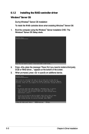
... or RAID driver... 2. Windows Setup Setup could not determine the type of the screen. 3. The Windows® Server OS Setup starts. Currently, Setup will load support for the following mass storage devices(s): * To specify additional SCSI adapters, DVD-ROM drives, or special disk controllers for use with Windows, press ENTER. S=Specify Additional Device ENTER=Continue F3=Exit 6-6 Chapter 6: Driver installation 6.1.2 Installing the RAID controller driver Windows® Server OS During Windows® Server OS installation To install the RAID controller driver when installing Windows®...
... or RAID driver... 2. Windows Setup Setup could not determine the type of the screen. 3. The Windows® Server OS Setup starts. Currently, Setup will load support for the following mass storage devices(s): * To specify additional SCSI adapters, DVD-ROM drives, or special disk controllers for use with Windows, press ENTER. S=Specify Additional Device ENTER=Continue F3=Exit 6-6 Chapter 6: Driver installation 6.1.2 Installing the RAID controller driver Windows® Server OS During Windows® Server OS installation To install the RAID controller driver when installing Windows®...
User Manual
Page 137
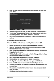
... 5. Select the option Install the software automatically (Recommended), and then click Next. 10. Click Cancel. 3. Click the Driver tab, and then click the Update Driver button. 7. Click Finish after the driver installation is done. Windows Setup Please insert the disk labeled Manufacturer-supplied hardware support disk into Drive A: * Press ENTER when ready. Setup then proceeds with Administrator privileges. 2. The wizard searches the RAID controller drivers. The Windows® Setup loads the RAID controller drivers from the menu. 4. Click...
... 5. Select the option Install the software automatically (Recommended), and then click Next. 10. Click Cancel. 3. Click the Driver tab, and then click the Update Driver button. 7. Click Finish after the driver installation is done. Windows Setup Please insert the disk labeled Manufacturer-supplied hardware support disk into Drive A: * Press ENTER when ready. Setup then proceeds with Administrator privileges. 2. The wizard searches the RAID controller drivers. The Windows® Setup loads the RAID controller drivers from the menu. 4. Click...

User Manual
Page 148
... device OK Back The drivers for the RAID controller are installed to continue. 5. 4. When below screen appears, select the floppy disk drive (fd0) as the driver update medium. Make sure that Installation from Hard Disk Installation Installation--ACPI Disabled Installation--Local APIC Disabled Installation--Safe Settings Rescue System Memory Test Boot Options | F1 Help F2 Language F3 1280 x 1024 F4 DVD F5 Driver If you install SLES 10, type brokenmodules=ahci after Boot Options and press Enter to the system. 6-18 Chapter 6: Driver installation Boot from the Boot Options menu...
... device OK Back The drivers for the RAID controller are installed to continue. 5. 4. When below screen appears, select the floppy disk drive (fd0) as the driver update medium. Make sure that Installation from Hard Disk Installation Installation--ACPI Disabled Installation--Local APIC Disabled Installation--Safe Settings Rescue System Memory Test Boot Options | F1 Help F2 Language F3 1280 x 1024 F4 DVD F5 Driver If you install SLES 10, type brokenmodules=ahci after Boot Options and press Enter to the system. 6-18 Chapter 6: Driver installation Boot from the Boot Options menu...
User Manual
Page 156
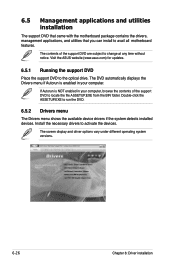
... locate the file ASSETUP.EXE from the BIN folder. Visit the ASUS website (www.asus.com) for updates. 6.5.1 Running the support DVD Place the support DVD to avail all motherboard features. 6.5 Management applications and utilities installation The support DVD that came with the motherboard package contains the drivers, management applications, and utilities that you can install to the optical drive. The screen display and driver options vary under different operating system versions. 6-26 Chapter 6: Driver installation...
... locate the file ASSETUP.EXE from the BIN folder. Visit the ASUS website (www.asus.com) for updates. 6.5.1 Running the support DVD Place the support DVD to avail all motherboard features. 6.5 Management applications and utilities installation The support DVD that came with the motherboard package contains the drivers, management applications, and utilities that you can install to the optical drive. The screen display and driver options vary under different operating system versions. 6-26 Chapter 6: Driver installation...


