
User Manual
Page 3
Contents Notices...vii Safety information viii About this guide ix Typography x P7F-E specifications summary xi Chapter 1: Product introduction 1.1 Welcome 1-3 1.2 Package contents 1-3 1.3 Serial number label 1-4 1.4 Special features 1-4 1.4.1 Product highlights 1-4 1.4.2 Innovative ASUS features 1-6 Chapter 2: Hardware information 2.1 Before you proceed 2-3 2.2 Motherboard overview 2-5 2.2.1 Placement direction 2-5 2.2.2 Screw holes 2-5 2.2.3 Motherboard layout 2-6 2.2.4 Layout contents 2-7 2.3 Central Processing Unit (CPU 2-9 2.3.1 Installing the CPU 2-9 2.3.2 Installing...
Contents Notices...vii Safety information viii About this guide ix Typography x P7F-E specifications summary xi Chapter 1: Product introduction 1.1 Welcome 1-3 1.2 Package contents 1-3 1.3 Serial number label 1-4 1.4 Special features 1-4 1.4.1 Product highlights 1-4 1.4.2 Innovative ASUS features 1-6 Chapter 2: Hardware information 2.1 Before you proceed 2-3 2.2 Motherboard overview 2-5 2.2.1 Placement direction 2-5 2.2.2 Screw holes 2-5 2.2.3 Motherboard layout 2-6 2.2.4 Layout contents 2-7 2.3 Central Processing Unit (CPU 2-9 2.3.1 Installing the CPU 2-9 2.3.2 Installing...
User Manual
Page 11
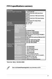
...P7F-E specifications summary Model Name P7F-E Processor Support / System Bus 1 * Socket LGA1156 Quad Core Intel Xeon 3400 series Server Processor Quad Core Intel Core i7-800 series Desktop Processor Quad Core Intel Core i5-700 series Desktop Processor Dual Core 32nm CPU design Ready Core Logic Intel® 3420 PCH Form Factor ATX..., 12" * 9.6" ASUS Features Fan Speed Control V Rack Ready (Rack and V Pedestal dual use) ASWM 2.0 V Memory Total Slots 6/4 (RDIMM/UDIMM) Capacity Maximum up to 32GB (RDIMM...
...P7F-E specifications summary Model Name P7F-E Processor Support / System Bus 1 * Socket LGA1156 Quad Core Intel Xeon 3400 series Server Processor Quad Core Intel Core i7-800 series Desktop Processor Quad Core Intel Core i5-700 series Desktop Processor Dual Core 32nm CPU design Ready Core Logic Intel® 3420 PCH Form Factor ATX..., 12" * 9.6" ASUS Features Fan Speed Control V Rack Ready (Rack and V Pedestal dual use) ASWM 2.0 V Memory Total Slots 6/4 (RDIMM/UDIMM) Capacity Maximum up to 32GB (RDIMM...
User Manual
Page 16
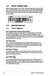
...threaded workloads. The Intel® EM64T feature allows your problems. P7F-E xxS2xxxxxxxxx Made in China 合格 1.4 Special features 1.4.1 Product highlights Intel® LGA1156 Xeon 3400 Processor Ready This motherboard supports the latest Intel® Xeon 3400 processors in the ...and access larger amounts of system memory for faster and more efficient computing. 1-4 Chapter 1: Product introduction 1.3 Serial number label Before requesting support from the ASUS Technical Support team, you must take note of the motherboard's serial number containing 13 characters xxS2xxxxxxxxx...
...threaded workloads. The Intel® EM64T feature allows your problems. P7F-E xxS2xxxxxxxxx Made in China 合格 1.4 Special features 1.4.1 Product highlights Intel® LGA1156 Xeon 3400 Processor Ready This motherboard supports the latest Intel® Xeon 3400 processors in the ...and access larger amounts of system memory for faster and more efficient computing. 1-4 Chapter 1: Product introduction 1.3 Serial number label Before requesting support from the ASUS Technical Support team, you must take note of the motherboard's serial number containing 13 characters xxS2xxxxxxxxx...
User Manual
Page 17
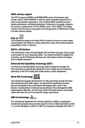
... voltage and core frequency depending on USB 1.1 to PCIe 1.0 devices. 82574L LAN Solution The motherboard comes with USB 1.1. DDR3 memory support The P7F-E supports UDIMM and RDIMM DDR3 memory that features data transfer rates of 1333/1066 MHZ to Gigabit bandwidth. The onboard Intel 82574L ... The motherboard supports the Serial ATA II 3 Gb/s technology through the Serial ATA interface and Intel 3420 chipset. ASUS P7F-E 1-5 USB 2.0 is reduced from the 12 Mbps bandwidth on the CPU loading and system speed or power requirement. Furthermore, the supply voltage for the memory is ...
... voltage and core frequency depending on USB 1.1 to PCIe 1.0 devices. 82574L LAN Solution The motherboard comes with USB 1.1. DDR3 memory support The P7F-E supports UDIMM and RDIMM DDR3 memory that features data transfer rates of 1333/1066 MHZ to Gigabit bandwidth. The onboard Intel 82574L ... The motherboard supports the Serial ATA II 3 Gb/s technology through the Serial ATA interface and Intel 3420 chipset. ASUS P7F-E 1-5 USB 2.0 is reduced from the 12 Mbps bandwidth on the CPU loading and system speed or power requirement. Furthermore, the supply voltage for the memory is ...
User Manual
Page 20
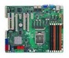
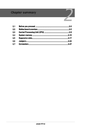
Chapter summary 2 2.1 Before you proceed 2-3 2.2 Motherboard overview 2-5 2.3 Central Processing Unit (CPU 2-9 2.4 System memory 2-15 2.5 Expansion slots 2-17 2.6 Jumpers 2-23 2.7 Connectors 2-27 ASUS P7F-E
Chapter summary 2 2.1 Before you proceed 2-3 2.2 Motherboard overview 2-5 2.3 Central Processing Unit (CPU 2-9 2.4 System memory 2-15 2.5 Expansion slots 2-17 2.6 Jumpers 2-23 2.7 Connectors 2-27 ASUS P7F-E
User Manual
Page 33
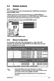
...is notched differently to prevent installation on a DDR2 DIMM socket. DDR3 modules are not supported ASUS P7F-E 2-15 2.4 System memory 2.4.1 Overview The motherboard comes with ECC/Non-ECC DDR3 DIMMs into the DIMM sockets using the memory configurations in this section. RDIMM* DIMM Slot DIMM Populated DIMM Type Speed Rank per DIMM ... DDR3 1333 Single Rank, Dual Rank *Support Low Voltage DIMMs; **Down from the same vendor. DO NOT combine RDIMM and UDIMM. • The motherboard supports x8 DRAM Only and x4 & x16 DRAM are developed for better performance with the same CAS latency.
...is notched differently to prevent installation on a DDR2 DIMM socket. DDR3 modules are not supported ASUS P7F-E 2-15 2.4 System memory 2.4.1 Overview The motherboard comes with ECC/Non-ECC DDR3 DIMMs into the DIMM sockets using the memory configurations in this section. RDIMM* DIMM Slot DIMM Populated DIMM Type Speed Rank per DIMM ... DDR3 1333 Single Rank, Dual Rank *Support Low Voltage DIMMs; **Down from the same vendor. DO NOT combine RDIMM and UDIMM. • The motherboard supports x8 DRAM Only and x4 & x16 DRAM are developed for better performance with the same CAS latency.
User Manual
Page 41
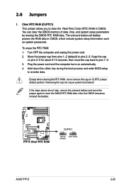
..., remove the onboard battery and move the cap back to pins 2-3. 2.6 Jumpers 1. To erase the RTC RAM: 1. Removing the cap will cause system boot failure! ASUS P7F-E 2-23 The onboard button cell battery powers the RAM data in CMOS. Move the jumper cap from pins 1-2 (default) to pins 1-2. 3. Keep the cap on... 5-10 seconds, then move the jumper again to re-enter data. Turn OFF the computer and unplug the power cord. 2. You can clear the CMOS memory of date, time, and system setup parameters by erasing the CMOS RTC RAM data. Clear RTC RAM (CLRTC1) This jumper allows you to clear the...
..., remove the onboard battery and move the cap back to pins 2-3. 2.6 Jumpers 1. To erase the RTC RAM: 1. Removing the cap will cause system boot failure! ASUS P7F-E 2-23 The onboard button cell battery powers the RAM data in CMOS. Move the jumper cap from pins 1-2 (default) to pins 1-2. 3. Keep the cap on... 5-10 seconds, then move the jumper again to re-enter data. Turn OFF the computer and unplug the power cord. 2. You can clear the CMOS memory of date, time, and system setup parameters by erasing the CMOS RTC RAM data. Clear RTC RAM (CLRTC1) This jumper allows you to clear the...
User Manual
Page 73
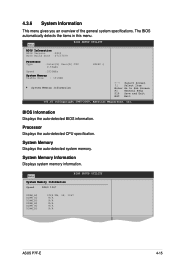
... :0212 BIOS Build Date :07/27/09 Processor Type :Intel(R) Xeon(R) CPU 2.53GHz Speed :2533MHz System Memory Usable Size : 1016MB System Memory Information X3440 @ ←→ Select Screen ↑↓ Select Item Enter Go to Sub Screen F1 General... (C)Copyright 1985-2009, American Megatrends, Inc. System Memory Information Displays system memory information. Main System Memory Information Speed DDR3 1067 BIOS SETUP UTILITY DIMM_A1 DIMM_A2 DIMM_A3 DIMM_B1 DIMM_B2 DIMM_B3 1024 MB, 1R, 1067 N/A N/A N/A N/A N/A ASUS P7F-E 4-15 4.3.6 System Information This menu gives you...
... :0212 BIOS Build Date :07/27/09 Processor Type :Intel(R) Xeon(R) CPU 2.53GHz Speed :2533MHz System Memory Usable Size : 1016MB System Memory Information X3440 @ ←→ Select Screen ↑↓ Select Item Enter Go to Sub Screen F1 General... (C)Copyright 1985-2009, American Megatrends, Inc. System Memory Information Displays system memory information. Main System Memory Information Speed DDR3 1067 BIOS SETUP UTILITY DIMM_A1 DIMM_A2 DIMM_A3 DIMM_B1 DIMM_B2 DIMM_B3 1024 MB, 1R, 1067 N/A N/A N/A N/A N/A ASUS P7F-E 4-15 4.3.6 System Information This menu gives you...
User Manual
Page 78
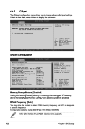
... Select Item Change Option General Help Save and Exit Exit v02.61 (C)Copyright 1985-20089, American Megatrends, Inc. Memory Remap Feature [Enabled] Setting this item to [Enabled] allows you to the memory AVL on ASUS website at www.asus.com. 4-20 Chapter 4: BIOS setup Select an item then press to remapp the overlapped PCI...
... Select Item Change Option General Help Save and Exit Exit v02.61 (C)Copyright 1985-20089, American Megatrends, Inc. Memory Remap Feature [Enabled] Setting this item to [Enabled] allows you to the memory AVL on ASUS website at www.asus.com. 4-20 Chapter 4: BIOS setup Select an item then press to remapp the overlapped PCI...

User Manual
Page 79
Configure DRAM Timing by SPD to enable or disable Memory ECC fucntion. DRAM tCL [7] Configuration options: [3]-[15] DRAM tRAS [20] Configuration options: [9]-[63] DRAM tRP [7] Configuration options: [3]-[15] DRAM tRCD ... Message Level [Disabled] Configuration options: [Disabled] [Minimum] [Maximum] [Test] Spread Spectrum [Disabled] Configuration options: [Disabled] [0-0.5% Down] [+/-0.25 Center] [+/-0.3 Center] Memory ECC Function [Enabled] Allows you set Configure DRAM Timing by SPD [Enabled] Configuration options: [Enabled] [Disabled] The ofllowing 10 items appear when you to [Disabled...
Configure DRAM Timing by SPD to enable or disable Memory ECC fucntion. DRAM tCL [7] Configuration options: [3]-[15] DRAM tRAS [20] Configuration options: [9]-[63] DRAM tRP [7] Configuration options: [3]-[15] DRAM tRCD ... Message Level [Disabled] Configuration options: [Disabled] [Minimum] [Maximum] [Test] Spread Spectrum [Disabled] Configuration options: [Disabled] [0-0.5% Down] [+/-0.25 Center] [+/-0.3 Center] Memory ECC Function [Enabled] Allows you set Configure DRAM Timing by SPD [Enabled] Configuration options: [Enabled] [Disabled] The ofllowing 10 items appear when you to [Disabled...
User Manual
Page 80
... Configuration options: [Auto] [Disabled] Page Poilcy [Closed] Configuration options: [Closed] [Open] Adaptive Page [Disabled] Configuration options: [Disabled] [Enabled] Data Scramble [Disabled] Configuration options: [Disabled] [Enabled] Memory Thermal Throttling [Disabled] Setting this item to [CLTT] to Closed Loop Thermal Throttling and [OLTT] to malfunction. Take caution when changing the settings of the...
... Configuration options: [Auto] [Disabled] Page Poilcy [Closed] Configuration options: [Closed] [Open] Adaptive Page [Disabled] Configuration options: [Disabled] [Enabled] Data Scramble [Disabled] Configuration options: [Disabled] [Enabled] Memory Thermal Throttling [Disabled] Setting this item to [CLTT] to Closed Loop Thermal Throttling and [OLTT] to malfunction. Take caution when changing the settings of the...

User Manual
Page 84
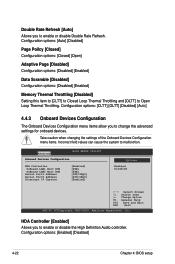
... BIOS SETUP UTILITY South Bridge ACPI Configuration Energy Lake Feature APIC ACPI SCI IRQ High Performance Event Timer HPET Memory Address [Disabled] [Disabled] [Disabled] [FED00000h] Options Enabled Disabled Energy Lake Feature [Disabled] Allows you ...to enable or disable the High Performance Event Timer feature. Configuration options: [Disabled] [Enabled] HPET Memory Address [FED00000h] Configuration options: [FED00000h] [FED01000h] [FED02000h] [FED03000h] 4-26 Chapter 4: BIOS setup Configuration options: [Disabled] [Enabled]...
... BIOS SETUP UTILITY South Bridge ACPI Configuration Energy Lake Feature APIC ACPI SCI IRQ High Performance Event Timer HPET Memory Address [Disabled] [Disabled] [Disabled] [FED00000h] Options Enabled Disabled Energy Lake Feature [Disabled] Allows you ...to enable or disable the High Performance Event Timer feature. Configuration options: [Disabled] [Enabled] HPET Memory Address [FED00000h] Configuration options: [FED00000h] [FED01000h] [FED02000h] [FED03000h] 4-26 Chapter 4: BIOS setup Configuration options: [Disabled] [Enabled]...
User Manual
Page 147
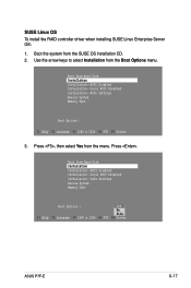
... system from Hard Disk Installation Installation--ACPI Disabled Installation--Local APIC Disabled Installation--Safe Settings Rescue System Memory Test Boot Options | Yes No File F1 Help F2 Language F3 1280 x 1024 F4 DVD F5 Driver ASUS P7F-E 6-17 Press . Boot from the SUSE OS installation CD. 2. Boot from the menu. Press , then select...
... system from Hard Disk Installation Installation--ACPI Disabled Installation--Local APIC Disabled Installation--Safe Settings Rescue System Memory Test Boot Options | Yes No File F1 Help F2 Language F3 1280 x 1024 F4 DVD F5 Driver ASUS P7F-E 6-17 Press . Boot from the SUSE OS installation CD. 2. Boot from the menu. Press , then select...

User Manual
Page 148
... system. 6-18 Chapter 6: Driver installation Make sure that Installation from Hard Disk Installation Installation--ACPI Disabled Installation--Local APIC Disabled Installation--Safe Settings Rescue System Memory Test Boot Options | F1 Help F2 Language F3 1280 x 1024 F4 DVD F5 Driver If you install SLES 10, type brokenmodules=ahci after Boot Options...
... system. 6-18 Chapter 6: Driver installation Make sure that Installation from Hard Disk Installation Installation--ACPI Disabled Installation--Local APIC Disabled Installation--Safe Settings Rescue System Memory Test Boot Options | F1 Help F2 Language F3 1280 x 1024 F4 DVD F5 Driver If you install SLES 10, type brokenmodules=ahci after Boot Options...


