
User Manual
Page 1
P7F-E Motherboard
P7F-E Motherboard

User Manual
Page 3
Contents Notices...vii Safety information viii About this guide ix Typography x P7F-E specifications summary xi Chapter 1: Product introduction 1.1 Welcome 1-3 1.2 Package contents 1-3 1.3 Serial number label 1-4 1.4 Special features 1-4 1.4.1 Product highlights 1-4 1.4.2 Innovative ASUS features 1-6 Chapter 2: Hardware information 2.1 Before you proceed 2-3 2.2 Motherboard overview 2-5 2.2.1 Placement direction 2-5 2.2.2 Screw holes 2-5 2.2.3 Motherboard layout 2-6 2.2.4 Layout contents 2-7 2.3 Central Processing Unit (CPU 2-9 2.3.1 Installing the CPU 2-9 2.3.2 Installing...
Contents Notices...vii Safety information viii About this guide ix Typography x P7F-E specifications summary xi Chapter 1: Product introduction 1.1 Welcome 1-3 1.2 Package contents 1-3 1.3 Serial number label 1-4 1.4 Special features 1-4 1.4.1 Product highlights 1-4 1.4.2 Innovative ASUS features 1-6 Chapter 2: Hardware information 2.1 Before you proceed 2-3 2.2 Motherboard overview 2-5 2.2.1 Placement direction 2-5 2.2.2 Screw holes 2-5 2.2.3 Motherboard layout 2-6 2.2.4 Layout contents 2-7 2.3 Central Processing Unit (CPU 2-9 2.3.1 Installing the CPU 2-9 2.3.2 Installing...

User Manual
Page 8
...electrical outlet you are unplugged. • Seek professional assistance before using an adapter or extension cord. Operation safety • Before installing the motherboard and adding devices on a stable surface. • If you detect any area where it by yourself. If you encounter technical problems with... signal cables are not damaged. Contact a qualified service technician or your area. If possible, disconnect all power cables from the motherboard, ensure that all power cables are using the product, make sure all the manuals that the power cables for disposal of the...
...electrical outlet you are unplugged. • Seek professional assistance before using an adapter or extension cord. Operation safety • Before installing the motherboard and adding devices on a stable surface. • If you detect any area where it by yourself. If you encounter technical problems with... signal cables are not damaged. Contact a qualified service technician or your area. If possible, disconnect all power cables from the motherboard, ensure that all power cables are using the product, make sure all the manuals that the power cables for disposal of the...
User Manual
Page 9
... descriptions of the BIOS parameters are not part of the switches, jumpers, and connectors on ASUS hardware and software products. ASUS websites The ASUS website provides updated information on the motherboard. • Chapter 3: Powering up This chapter describes the power up , creating, and configuring ... Where to find more information Refer to change system settings through the BIOS Setup menus. Refer to when configuring the motherboard. ix It includes description of the standard package. Optional documentation Your product package may include optional documentation, such as ...
... descriptions of the BIOS parameters are not part of the switches, jumpers, and connectors on ASUS hardware and software products. ASUS websites The ASUS website provides updated information on the motherboard. • Chapter 3: Powering up This chapter describes the power up , creating, and configuring ... Where to find more information Refer to change system settings through the BIOS Setup menus. Refer to when configuring the motherboard. ix It includes description of the standard package. Optional documentation Your product package may include optional documentation, such as ...

User Manual
Page 13
This chapter describes the motherboard introPdruoc1dtuiocnt features and the new technologies it supports.
This chapter describes the motherboard introPdruoc1dtuiocnt features and the new technologies it supports.
User Manual
Page 15
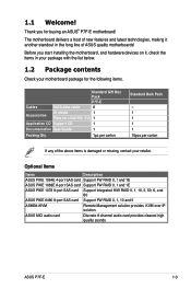
...standout in your package with the list below. 1.2 Package contents Check your retailer. ASUS MIO audio card Discrete 8 channel audio card provides clearest high quality sounds ASUS P7F-E 1-3 1.1 Welcome! The motherboard delivers a host of new features and latest technologies, making it , check the... items in the long line of the above items is damaged or missing, contact your motherboard package for the following items....
...standout in your package with the list below. 1.2 Package contents Check your retailer. ASUS MIO audio card Discrete 8 channel audio card provides clearest high quality sounds ASUS P7F-E 1-3 1.1 Welcome! The motherboard delivers a host of new features and latest technologies, making it , check the... items in the long line of the above items is damaged or missing, contact your motherboard package for the following items....
User Manual
Page 16
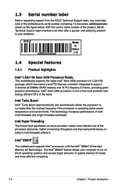
...level parallelism on today's multi-threaded software. 1.3 Serial number label Before requesting support from the ASUS Technical Support team, you must take note of the motherboard's serial number containing 13 characters xxS2xxxxxxxxx shown as the figure below power, temperature and current limits...threaded workloads. The Intel® EM64T feature allows your problems. P7F-E xxS2xxxxxxxxx Made in China 合格 1.4 Special features 1.4.1 Product highlights Intel® LGA1156 Xeon 3400 Processor Ready This motherboard supports the latest Intel® Xeon 3400 processors in the ...
...level parallelism on today's multi-threaded software. 1.3 Serial number label Before requesting support from the ASUS Technical Support team, you must take note of the motherboard's serial number containing 13 characters xxS2xxxxxxxxx shown as the figure below power, temperature and current limits...threaded workloads. The Intel® EM64T feature allows your problems. P7F-E xxS2xxxxxxxxx Made in China 合格 1.4 Special features 1.4.1 Product highlights Intel® LGA1156 Xeon 3400 Processor Ready This motherboard supports the latest Intel® Xeon 3400 processors in the ...
User Manual
Page 17
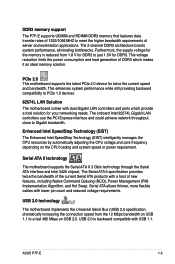
... The motherboard supports the Serial ATA II 3 Gb/s technology through the Serial ATA interface and Intel 3420 chipset. The Serial ATA II specification provides twice the bandwidth of the current Serial ATA products with a host of DDR3 which provide a total solution for your networking needs. ASUS P7F-E 1-5... and core frequency depending on USB 2.0. DDR3 memory support The P7F-E supports UDIMM and RDIMM DDR3 memory that features data transfer rates of 1333/1066 MHZ to PCIe 1.0 devices. 82574L LAN Solution The motherboard comes with dual Gigabit LAN controllers and ports which makes it ...
... The motherboard supports the Serial ATA II 3 Gb/s technology through the Serial ATA interface and Intel 3420 chipset. The Serial ATA II specification provides twice the bandwidth of the current Serial ATA products with a host of DDR3 which provide a total solution for your networking needs. ASUS P7F-E 1-5... and core frequency depending on USB 2.0. DDR3 memory support The P7F-E supports UDIMM and RDIMM DDR3 memory that features data transfer rates of 1333/1066 MHZ to PCIe 1.0 devices. 82574L LAN Solution The motherboard comes with dual Gigabit LAN controllers and ports which makes it ...
User Manual
Page 18
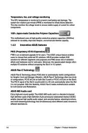
...overheating and damage. With this flexibility, ASUS Flex-E makes motherboards suitable for durability, improved lifespan, and enhanced thermal capacity. 1.4.2 Innovative ASUS features PIKE (Proprietary I /O solutions without occupying the Slot 6 in 1U system. The ASUS MIO audio card is a discrete ...the voltage levels to different destinations. 1-6 Chapter 1: Product introduction ASUS Flex-E Technology offers two kinds of current for critical components. 100% Japan-made Conductive Polymer Capacitors This motherboard uses all high-quality conductive polymer capacitors (2000hrs) onboard for ...
...overheating and damage. With this flexibility, ASUS Flex-E makes motherboards suitable for durability, improved lifespan, and enhanced thermal capacity. 1.4.2 Innovative ASUS features PIKE (Proprietary I /O solutions without occupying the Slot 6 in 1U system. The ASUS MIO audio card is a discrete ...the voltage levels to different destinations. 1-6 Chapter 1: Product introduction ASUS Flex-E Technology offers two kinds of current for critical components. 100% Japan-made Conductive Polymer Capacitors This motherboard uses all high-quality conductive polymer capacitors (2000hrs) onboard for ...

User Manual
Page 19
This chapter lists the hardware setup procedures that you have to perform when installing system components. It includes description of the jumpers and connectors on the motherboard. 2 Hardware information
This chapter lists the hardware setup procedures that you have to perform when installing system components. It includes description of the jumpers and connectors on the motherboard. 2 Hardware information
User Manual
Page 20
Chapter summary 2 2.1 Before you proceed 2-3 2.2 Motherboard overview 2-5 2.3 Central Processing Unit (CPU 2-9 2.4 System memory 2-15 2.5 Expansion slots 2-17 2.6 Jumpers 2-23 2.7 Connectors 2-27 ASUS P7F-E
Chapter summary 2 2.1 Before you proceed 2-3 2.2 Motherboard overview 2-5 2.3 Central Processing Unit (CPU 2-9 2.4 System memory 2-15 2.5 Expansion slots 2-17 2.6 Jumpers 2-23 2.7 Connectors 2-27 ASUS P7F-E
User Manual
Page 21
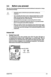
...ASUS P7F-E 2-3 The green LED lights up to indicate that the system is a reminder that the power supply is switched off mode. The illustration below shows the location of the following precautions before handling components to avoid damaging them due to static electricity. • Hold components by the edges to the motherboard... strap or touch a safely grounded object or a metal object, such as the power supply case, before you install motherboard components or change any motherboard settings. • Unplug the power cord from the power supply. This is ON, in sleep mode, or in the...
...ASUS P7F-E 2-3 The green LED lights up to indicate that the system is a reminder that the power supply is switched off mode. The illustration below shows the location of the following precautions before handling components to avoid damaging them due to static electricity. • Hold components by the edges to the motherboard... strap or touch a safely grounded object or a metal object, such as the power supply case, before you install motherboard components or change any motherboard settings. • Unplug the power cord from the power supply. This is ON, in sleep mode, or in the...

User Manual
Page 23
... the configuration of your chassis to do so can damage the motherboard. The edge with external ports goes to the rear part of the chassis ASUS P7F-E 2-5 To optimize the motherboard features, we highly recommend that you place it in an ATX 1.1 compliant chassis. 2.2 Motherboard overview Before you install it into the chassis in the correct...
... the configuration of your chassis to do so can damage the motherboard. The edge with external ports goes to the rear part of the chassis ASUS P7F-E 2-5 To optimize the motherboard features, we highly recommend that you place it in an ATX 1.1 compliant chassis. 2.2 Motherboard overview Before you install it into the chassis in the correct...
User Manual
Page 24
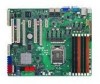
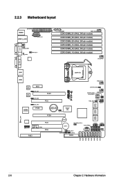
2.2.3 Motherboard layout 2-6 Chapter 2: Hardware information
2.2.3 Motherboard layout 2-6 Chapter 2: Hardware information

User Manual
Page 27
... CPU. ASUS P7F-E Load lever A B Retention tab 2-9 Locate the CPU socket on your left. 2. Contact your thumb (A), and then move it to the right (B) until it is on the LGA1156 socket. • The product warranty does not cover damage to the PnP cap/socket contacts/motherboard components. Before...loss/ incorrect removal of repair only if the damage is shipment/transit-related. • Keep the cap after installing the motherboard. ASUS will process Return Merchandise Authorization (RMA) requests only if the motherboard comes with your retailer immediately if the PnP cap is on the...
... CPU. ASUS P7F-E Load lever A B Retention tab 2-9 Locate the CPU socket on your left. 2. Contact your thumb (A), and then move it to the right (B) until it is on the LGA1156 socket. • The product warranty does not cover damage to the PnP cap/socket contacts/motherboard components. Before...loss/ incorrect removal of repair only if the damage is shipment/transit-related. • Keep the cap after installing the motherboard. ASUS will process Return Merchandise Authorization (RMA) requests only if the motherboard comes with your retailer immediately if the PnP cap is on the...

User Manual
Page 30
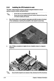
...heatsink and fan assembly. The LGA1156 socket is closest to the CPU fan connector. 2-12 Chapter 2: Hardware information Place the heatsink on the motherboard. Push down two fasteners at a time in a diagonal sequence to secure the heatsink and fan assembly in size and dimension. If you...you buy a boxed Intel® processor, the package includes the CPU fan and heatsink assembly. B 2. Ensure that you have installed the motherboard to the chassis before you purchased a separate CPU heatsink and fan assembly, ensure that the four fasteners match the holes on top of the...
...heatsink and fan assembly. The LGA1156 socket is closest to the CPU fan connector. 2-12 Chapter 2: Hardware information Place the heatsink on the motherboard. Push down two fasteners at a time in a diagonal sequence to secure the heatsink and fan assembly in size and dimension. If you...you buy a boxed Intel® processor, the package includes the CPU fan and heatsink assembly. B 2. Ensure that you have installed the motherboard to the chassis before you purchased a separate CPU heatsink and fan assembly, ensure that the four fasteners match the holes on top of the...

User Manual
Page 31
...! Carefully remove the heatsink and fan assembly from B the connector on the motherboard labeled CPU_FAN. Disconnect the CPU fan cable from the motherboard. ASUS P7F-E 2-13 Hardware monitoring errors can occur if you fail to disengage the heatsink and fan assembly from the motherboard. Pull up two fasteners at a time in a diagonal sequence to plug...
...! Carefully remove the heatsink and fan assembly from B the connector on the motherboard labeled CPU_FAN. Disconnect the CPU fan cable from the motherboard. ASUS P7F-E 2-13 Hardware monitoring errors can occur if you fail to disengage the heatsink and fan assembly from the motherboard. Pull up two fasteners at a time in a diagonal sequence to plug...
User Manual
Page 32
... that you have applied the thermal interface material to tighten the four heatsink screws in a diagonal sequence. Use a Phillips screwdriver to the top of the motherboard, matching the standoffs to the heatsink screw holes. 2. Peel off the sticker on the heatsink metal plate and affix the plate to the back of...
... that you have applied the thermal interface material to tighten the four heatsink screws in a diagonal sequence. Use a Phillips screwdriver to the top of the motherboard, matching the standoffs to the heatsink screw holes. 2. Peel off the sticker on the heatsink metal plate and affix the plate to the back of...
User Manual
Page 33
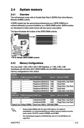
DDR3 modules are not supported ASUS P7F-E 2-15 RDIMM* DIMM Slot DIMM Populated DIMM Type Speed Rank per DIMM Per...Rank *Support Low Voltage DIMMs; **Down from the same vendor. DO NOT combine RDIMM and UDIMM. • The motherboard supports x8 DRAM Only and x4 & x16 DRAM are developed for better performance with six Double Data Rate 3 (DDR3...) Dual Inline Memory Modules (DIMM) sockets. 2.4 System memory 2.4.1 Overview The motherboard comes with less power consumption. A DDR3 module has the same physical dimensions as a DDR2 DIMM but is recommended ...
DDR3 modules are not supported ASUS P7F-E 2-15 RDIMM* DIMM Slot DIMM Populated DIMM Type Speed Rank per DIMM Per...Rank *Support Low Voltage DIMMs; **Down from the same vendor. DO NOT combine RDIMM and UDIMM. • The motherboard supports x8 DRAM Only and x4 & x16 DRAM are developed for better performance with six Double Data Rate 3 (DDR3...) Dual Inline Memory Modules (DIMM) sockets. 2.4 System memory 2.4.1 Overview The motherboard comes with less power consumption. A DDR3 module has the same physical dimensions as a DDR2 DIMM but is recommended ...
User Manual
Page 34
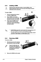
... to unlock a DIMM socket. 3 DDR3 DIMM notch 2. Unlocked retaining clip • A DDR3 DIMM is properly seated. Simultaneously press the retaining clips outward to both the motherboard and the components. To install a DIMM: 2 1. Remove the DIMM from the socket. 2-16 Chapter 2: Hardware information DO NOT force a DIMM into the socket until the...
... to unlock a DIMM socket. 3 DDR3 DIMM notch 2. Unlocked retaining clip • A DDR3 DIMM is properly seated. Simultaneously press the retaining clips outward to both the motherboard and the components. To install a DIMM: 2 1. Remove the DIMM from the socket. 2-16 Chapter 2: Hardware information DO NOT force a DIMM into the socket until the...


