
Motherboard Installation Guide
Page 47
EZFlash starting BIOS update Checking for floppy... Rebooting. • • 2-3 Floppy found! Reading file "P5V800MX.rom". EZFlash starting BIOS update Checking for floppy... Start erasing.......| Start programming...| Flashed successfully. Completed.
EZFlash starting BIOS update Checking for floppy... Rebooting. • • 2-3 Floppy found! Reading file "P5V800MX.rom". EZFlash starting BIOS update Checking for floppy... Start erasing.......| Start programming...| Flashed successfully. Completed.

Motherboard Installation Guide
Page 50
Bad BIOS checksum. Completed. Bad BIOS checksum. Checking for floppy... Floppy found! Reading file "P5V800MX.ROM". Start flashing... 2-6 Starting BIOS recovery... Starting BIOS recovery... Checking for floppy...
Bad BIOS checksum. Completed. Bad BIOS checksum. Checking for floppy... Floppy found! Reading file "P5V800MX.ROM". Start flashing... 2-6 Starting BIOS recovery... Starting BIOS recovery... Checking for floppy...

Motherboard Installation Guide
Page 51
Checking for floppy... CD-ROM found ! Starting BIOS recovery... Checking for floppy... Reading file "P5V800MX.ROM". Completed. Bad BIOS checksum. Start flashing... 2-7 Bad BIOS checksum. Floppy not found ! Checking for CD-ROM... Starting BIOS recovery...
Checking for floppy... CD-ROM found ! Starting BIOS recovery... Checking for floppy... Reading file "P5V800MX.ROM". Completed. Bad BIOS checksum. Start flashing... 2-7 Bad BIOS checksum. Floppy not found ! Checking for CD-ROM... Starting BIOS recovery...

Motherboard Installation Guide
Page 56
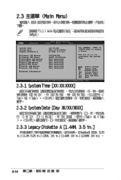
... Select Field F1 General Help F10 Save and Exit ESC Exit v02.58 (C)Copyright 1985-2004, American Megatrends, Inc. 2-12 Main Advanced BIOS SETUP UTILITY Power Boot Exit System Time System Date Legacy Diskette A Primary IDE Master Primary IDE Slave Secondary IDE Master Secondary IDE Slave Third... IDE Master Third IDE Slave Fourth IDE Master Fourth IDE Slave System Information [10:55:25] [Thu 09/15/2005] [1.44M, 3.5 in] [ST320410A] [ASUS CD-S520/A] [Not Detected] [Not Detected] [Not Detected] [Not Detected] [Not Detected] [Not Detected] Use [ENTER], [TAB] or [SHIFT-TAB] to...
... Select Field F1 General Help F10 Save and Exit ESC Exit v02.58 (C)Copyright 1985-2004, American Megatrends, Inc. 2-12 Main Advanced BIOS SETUP UTILITY Power Boot Exit System Time System Date Legacy Diskette A Primary IDE Master Primary IDE Slave Secondary IDE Master Secondary IDE Slave Third... IDE Master Third IDE Slave Fourth IDE Master Fourth IDE Slave System Information [10:55:25] [Thu 09/15/2005] [1.44M, 3.5 in] [ST320410A] [ASUS CD-S520/A] [Not Detected] [Not Detected] [Not Detected] [Not Detected] [Not Detected] [Not Detected] Use [ENTER], [TAB] or [SHIFT-TAB] to...
Motherboard Installation Guide
Page 58
...Tab Select Field F1 General Help F10 Save and Exit ESC Exit v02.58 (C)Copyright 1985-2004, American Megatrends, Inc. 2-14 Main Advanced BIOS SETUP UTILITY Power Boot Exit System Time System Date Legacy Diskette A Primary IDE Master Primary IDE Slave Secondary IDE Master Secondary IDE Slave Third ...IDE Master Third IDE Slave Fourth IDE Master Fourth IDE Slave System Information [10:55:25] [Thu 07/21/2005] [1.44M, 3.5 in] [ST320410A] [ASUS CD-S520/A] [Not Detected] [Not Detected] [Not Detected] [Not Detected] [Not Detected] [Not Detected] Use [ENTER], [TAB] or [SHIFT-TAB] to...
...Tab Select Field F1 General Help F10 Save and Exit ESC Exit v02.58 (C)Copyright 1985-2004, American Megatrends, Inc. 2-14 Main Advanced BIOS SETUP UTILITY Power Boot Exit System Time System Date Legacy Diskette A Primary IDE Master Primary IDE Slave Secondary IDE Master Secondary IDE Slave Third ...IDE Master Third IDE Slave Fourth IDE Master Fourth IDE Slave System Information [10:55:25] [Thu 07/21/2005] [1.44M, 3.5 in] [ST320410A] [ASUS CD-S520/A] [Not Detected] [Not Detected] [Not Detected] [Not Detected] [Not Detected] [Not Detected] Use [ENTER], [TAB] or [SHIFT-TAB] to...

Motherboard Installation Guide
Page 62
Change Option F1 General Help F10 Save and Exit ESC Exit v02.58 (C)Copyright 1985-2004, American Megatrends, Inc. 2-18 Select Screen Select Item +- Advanced BIOS SETUP UTILITY USB Configuration Module Version - 2.24.0-11.4 USB Devices Enabled: None USB 1.1 Ports Configuration USB 2.0 Ports Enable Legacy USB Support USB 2.0 Controller Mode BIOS EHCI Hand-Off [Enabled] [Enable] [Auto] [FullSpeed] [Enabled] Enables 1.1 USB host controllers.
Change Option F1 General Help F10 Save and Exit ESC Exit v02.58 (C)Copyright 1985-2004, American Megatrends, Inc. 2-18 Select Screen Select Item +- Advanced BIOS SETUP UTILITY USB Configuration Module Version - 2.24.0-11.4 USB Devices Enabled: None USB 1.1 Ports Configuration USB 2.0 Ports Enable Legacy USB Support USB 2.0 Controller Mode BIOS EHCI Hand-Off [Enabled] [Enable] [Auto] [FullSpeed] [Enabled] Enables 1.1 USB host controllers.

Motherboard Installation Guide
Page 64
Northbridge Configuration Southbridge Configuration Options for DRAM 2-20 Advanced NorthBridge Configuration BIOS SETUP UTILITY DRAM Clock/Timing Configuration AGP & P2P Bridge Configuration Options for VIA P4M800 Select Screen Select Item Enter Go to malfunction. Advanced Advanced Chipset Settings BIOS SETUP UTILITY WARNING: Setting wrong values in below sections may cause system to Subscreen F1 General Help F10 Save and Exit ESC Exit v02.58 (C)Copyright 1985-2004, American Megatrends, Inc.
Northbridge Configuration Southbridge Configuration Options for DRAM 2-20 Advanced NorthBridge Configuration BIOS SETUP UTILITY DRAM Clock/Timing Configuration AGP & P2P Bridge Configuration Options for VIA P4M800 Select Screen Select Item Enter Go to malfunction. Advanced Advanced Chipset Settings BIOS SETUP UTILITY WARNING: Setting wrong values in below sections may cause system to Subscreen F1 General Help F10 Save and Exit ESC Exit v02.58 (C)Copyright 1985-2004, American Megatrends, Inc.

Motherboard Installation Guide
Page 66
Advanced BIOS SETUP UTILITY AGP & P2P Bridge Configuration Primary Graphics Adapter [PCI] AGP Aperture Size AGP 3.0 Mode AGP Fast Write VGA Frame Buffer Size [128MB] [8X] [Disabled] [64MB] Select Screen Select Item Enter Go to Subscreen F1 General Help F10 Save and Exit ESC Exit v02.58 (C)Copyright 1985-2004, American Megatrends, Inc. 2-22
Advanced BIOS SETUP UTILITY AGP & P2P Bridge Configuration Primary Graphics Adapter [PCI] AGP Aperture Size AGP 3.0 Mode AGP Fast Write VGA Frame Buffer Size [128MB] [8X] [Disabled] [64MB] Select Screen Select Item Enter Go to Subscreen F1 General Help F10 Save and Exit ESC Exit v02.58 (C)Copyright 1985-2004, American Megatrends, Inc. 2-22

Motherboard Installation Guide
Page 67
* Serial ATA IDE Controller * LAN Controller LAN Optional ROM * High Definition Audio [SATA] [Enabled] [Disabled] [Enabled] Advanced BIOS SETUP UTILITY Configure ITE8712 Super IO Chipset Serial Port1 Address Parallel Port Address Parallel Port Mode EPP Version ECP Mode DMA Channel Parallel Port IRQ Onboard Game Port Onboard MIDI Port [3F8/IRQ4] [378] [EPP+ECP] [1.9] [DMA3] [IRQ7] [Disabled] [Diaabled] Select Screen Select Item Enter Go to Subscreen F1 General Help F10 Save and Exit ESC Exit v02.58 (C)Copyright 1985-2004, American Megatrends, Inc. 2-23
* Serial ATA IDE Controller * LAN Controller LAN Optional ROM * High Definition Audio [SATA] [Enabled] [Disabled] [Enabled] Advanced BIOS SETUP UTILITY Configure ITE8712 Super IO Chipset Serial Port1 Address Parallel Port Address Parallel Port Mode EPP Version ECP Mode DMA Channel Parallel Port IRQ Onboard Game Port Onboard MIDI Port [3F8/IRQ4] [378] [EPP+ECP] [1.9] [DMA3] [IRQ7] [Disabled] [Diaabled] Select Screen Select Item Enter Go to Subscreen F1 General Help F10 Save and Exit ESC Exit v02.58 (C)Copyright 1985-2004, American Megatrends, Inc. 2-23

Motherboard Installation Guide
Page 70
Change Field F1 General Help F10 Save and Exit ESC Exit v02.58 (C)Copyright 1985-2004, American Megatrends, Inc. 2-26 Select Screen Select Item +- Main Advanced BIOS SETUP UTILITY Power Boot Exit Suspend Mode Repost Video on S3 Resume ACPI 2.0 Support ACPI APIC Support [Auto] [No] [No] [Enabled] APM Configuration Hardware Monitor Select the ACPI state used for System Suspend.
Change Field F1 General Help F10 Save and Exit ESC Exit v02.58 (C)Copyright 1985-2004, American Megatrends, Inc. 2-26 Select Screen Select Item +- Main Advanced BIOS SETUP UTILITY Power Boot Exit Suspend Mode Repost Video on S3 Resume ACPI 2.0 Support ACPI APIC Support [Auto] [No] [No] [Enabled] APM Configuration Hardware Monitor Select the ACPI state used for System Suspend.

Motherboard Installation Guide
Page 74
Boot Device Priority 1st Boot Device 2nd Boot Device 3rd Boot Device [1st FLOPPY DRIVE] [PM-ST330620A] [PS-ASUS CD-S360] Boot Settings Configuration Quick Boot Full Screen Logo AddOn ROM Display Mode Bootup Num-Lock Wait For 'F1' If Error Hit 'DEL' Message Display Interrupt 19 Capture [Enabled] [Enabled] [Force BIOS] [On] [Enabled] [Enabled] [Disabled] Allows BIOS to boot the system. 2-30 This will decrease the time needed to skip certain tests while booting.
Boot Device Priority 1st Boot Device 2nd Boot Device 3rd Boot Device [1st FLOPPY DRIVE] [PM-ST330620A] [PS-ASUS CD-S360] Boot Settings Configuration Quick Boot Full Screen Logo AddOn ROM Display Mode Bootup Num-Lock Wait For 'F1' If Error Hit 'DEL' Message Display Interrupt 19 Capture [Enabled] [Enabled] [Force BIOS] [On] [Enabled] [Enabled] [Disabled] Allows BIOS to boot the system. 2-30 This will decrease the time needed to skip certain tests while booting.

Motherboard Installation Guide
Page 87
RAID BIOS Ver 1.xx Auto Setup For Data Security Array Mode RAID 1 (Mirroring) Select Disk Drives Start Create Process Create a RAID array with the hard disks attached ...
RAID BIOS Ver 1.xx Auto Setup For Data Security Array Mode RAID 1 (Mirroring) Select Disk Drives Start Create Process Create a RAID array with the hard disks attached ...

P5V800-MX User's Manual for English Edition
Page 4
Contents 1.10.1 Rear panel connectors 1-23 1.10.2 Internal connectors 1-24 Chapter 2: BIOS setup 2.1 Managing and updating your BIOS 2-2 2.1.1 Creating a bootable floppy disk 2-2 2.1.2 ASUS EZ Flash utility 2-3 2.1.3 AFUDOS utility 2-4 2.1.4 ASUS CrashFree BIOS 2 utility 2-6 2.1.5 ASUS Update utility 2-8 2.2 BIOS setup program 2-11 2.2.2 Menu bar 2-12 2.2.3 Navigation keys 2-12 2.2.1 BIOS menu screen 2-12 2.2.4 Menu items 2-13 2.2.5 Sub-menu items 2-13 2.2.6 Configuration fields 2-13...
Contents 1.10.1 Rear panel connectors 1-23 1.10.2 Internal connectors 1-24 Chapter 2: BIOS setup 2.1 Managing and updating your BIOS 2-2 2.1.1 Creating a bootable floppy disk 2-2 2.1.2 ASUS EZ Flash utility 2-3 2.1.3 AFUDOS utility 2-4 2.1.4 ASUS CrashFree BIOS 2 utility 2-6 2.1.5 ASUS Update utility 2-8 2.2 BIOS setup program 2-11 2.2.2 Menu bar 2-12 2.2.3 Navigation keys 2-12 2.2.1 BIOS menu screen 2-12 2.2.4 Menu items 2-13 2.2.5 Sub-menu items 2-13 2.2.6 Configuration fields 2-13...

P5V800-MX User's Manual for English Edition
Page 8
... Where to find more information Refer to perform when installing system components. ASUS websites The ASUS website provides updated information on the motherboard. • Chapter 2: BIOS setup This chapter tells how to the ASUS contact information. 2. Refer to change system settings through the BIOS Setup menus. It includes description of the standard package. Detailed descriptions...
... Where to find more information Refer to perform when installing system components. ASUS websites The ASUS website provides updated information on the motherboard. • Chapter 2: BIOS setup This chapter tells how to the ASUS contact information. 2. Refer to change system settings through the BIOS Setup menus. It includes description of the standard package. Detailed descriptions...

P5V800-MX User's Manual for English Edition
Page 10
P5V800-MX specifications summary CPU Chipset Front Side Bus Memory Expansion slots VGA Storage Audio LAN USB Special features Rear panel BIOS features LGA775 socket for Intel® Pentium® D/Pentium® 4/ Celeron D processor Supports Intel® Pentium® 4 ...® AD1986A high definition audio 6-channel CODEC Audio Jack Sensing Technology Realtek® 10/100 Mbps Ethernet controller Supports up to 8 USB 2.0 ports ASUS Q-Fan ASUS EZ Flash ASUS CrashFree BIOS 2 1 x Parallel port 1 x LAN (RJ-45) port 4 x USB 2.0 ports 1 x VGA port 1 x Serial port (COM) 1 x PS/2 keyboard port 1 x ...
P5V800-MX specifications summary CPU Chipset Front Side Bus Memory Expansion slots VGA Storage Audio LAN USB Special features Rear panel BIOS features LGA775 socket for Intel® Pentium® D/Pentium® 4/ Celeron D processor Supports Intel® Pentium® 4 ...® AD1986A high definition audio 6-channel CODEC Audio Jack Sensing Technology Realtek® 10/100 Mbps Ethernet controller Supports up to 8 USB 2.0 ports ASUS Q-Fan ASUS EZ Flash ASUS CrashFree BIOS 2 1 x Parallel port 1 x LAN (RJ-45) port 4 x USB 2.0 ports 1 x VGA port 1 x Serial port (COM) 1 x PS/2 keyboard port 1 x ...

P5V800-MX User's Manual for English Edition
Page 16
... audio CODEC. With the CODEC, 6-channel audio ports, and S/ PDIF interfaces, you to restore the original BIOS data from a floppy disk. ASUS EZ Flash BIOS With the ASUS EZ Flash, you can connect your computer to home theater decoders to buy a replacement ROM chip. No need... to produce crystal-clear digital audio. 1.3.2 Innovative ASUS features CrashFree BIOS 2 This feature allows you can easily update the system BIOS even before loading the operating system. ASUS Q-Fan technology The ASUS Q-Fan technology smartly adjusts the CPU fan speed according to the system...
... audio CODEC. With the CODEC, 6-channel audio ports, and S/ PDIF interfaces, you to restore the original BIOS data from a floppy disk. ASUS EZ Flash BIOS With the ASUS EZ Flash, you can connect your computer to home theater decoders to buy a replacement ROM chip. No need... to produce crystal-clear digital audio. 1.3.2 Innovative ASUS features CrashFree BIOS 2 This feature allows you can easily update the system BIOS even before loading the operating system. ASUS Q-Fan technology The ASUS Q-Fan technology smartly adjusts the CPU fan speed according to the system...

P5V800-MX User's Manual for English Edition
Page 22
... a supported operating system. • For more information on the socket and damaging the CPU! Power up the system and enter the BIOS Setup (see Chapter 2: BIOS setup). Reboot the computer. 1-10 Chapter 1: Product introduction DO NOT force the CPU into the retention tab. Under Linux, use the...intel.com/info/hyperthreading. The item appears only if you are using any other operating systems, disable the Hyper-Threading Technology item in the BIOS to ensure system stability and performance. • Installing Windows® XP Service Pack 1 or later version is set to enable the ...
... a supported operating system. • For more information on the socket and damaging the CPU! Power up the system and enter the BIOS Setup (see Chapter 2: BIOS setup). Reboot the computer. 1-10 Chapter 1: Product introduction DO NOT force the CPU into the retention tab. Under Linux, use the...intel.com/info/hyperthreading. The item appears only if you are using any other operating systems, disable the Hyper-Threading Technology item in the BIOS to ensure system stability and performance. • Installing Windows® XP Service Pack 1 or later version is set to enable the ...

P5V800-MX User's Manual for English Edition
Page 30
... expansion card, read the documentation that came with the screw you may cause you intend to the tables on the system and change the necessary BIOS settings, if any. Turn on the next page. 3. Refer to use . 4. Install the software drivers for the card. 2. Failure to do so ... an IRQ to unplug the power cord before adding or removing expansion cards. Remove the system unit cover (if your motherboard is completely seated on BIOS setup. 2. Secure the card to install expansion cards. See Chapter 2 for later use . 1.8 Expansion slots In the future, you removed earlier. 6. The ...
... expansion card, read the documentation that came with the screw you may cause you intend to the tables on the system and change the necessary BIOS settings, if any. Turn on the next page. 3. Refer to use . 4. Install the software drivers for the card. 2. Failure to do so ... an IRQ to unplug the power cord before adding or removing expansion cards. Remove the system unit cover (if your motherboard is completely seated on BIOS setup. 2. Secure the card to install expansion cards. See Chapter 2 for later use . 1.8 Expansion slots In the future, you removed earlier. 6. The ...
P5V800-MX User's Manual for English Edition
Page 33
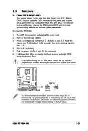
... default position. Hold down and reboot the system so the BIOS can clear the CMOS memory of date, time, and system setup parameters by erasing the CMOS RTC RAM data. For system failure due to re-enter data. ASUS P5V800-MX 1-21 The onboard button cell battery powers the RAM data ...to clear the Real Time Clock (RTC) RAM in CMOS, which include system setup information such as system passwords. Re-install the battery. 5. P5V800-MX ® P5V800-MX Clear RTC RAM CLRTC 12 23 Normal (Default) CLEAR You do not need to clear the RTC when the system hangs due to overclocking. 1.9...
... default position. Hold down and reboot the system so the BIOS can clear the CMOS memory of date, time, and system setup parameters by erasing the CMOS RTC RAM data. For system failure due to re-enter data. ASUS P5V800-MX 1-21 The onboard button cell battery powers the RAM data ...to clear the Real Time Clock (RTC) RAM in CMOS, which include system setup information such as system passwords. Re-install the battery. 5. P5V800-MX ® P5V800-MX Clear RTC RAM CLRTC 12 23 Normal (Default) CLEAR You do not need to clear the RTC when the system hangs due to overclocking. 1.9...

P5V800-MX User's Manual for English Edition
Page 34
... up from S1 sleep mode (CPU stopped, DRAM refreshed, system running in reduced power mode). KBPWR 12 23 +5V (Default) +5VSB P5V800-MX ® P5V800-MX Keyboard power setting 2. USB device wake-up (3-pin USBPW12, USBPW34, USBPW56, USBPW78) Set these jumpers to +5V to wake up feature....; P5V800-MX USB device wake-up +5V (Default) +5VSB USBPW56 USBPW78 2 1 +5V (Default) 3 2 +5VSB • The USB device wake-up . • The total current consumed must NOT exceed the power supply capability (+5VSB) whether under normal condition or in the BIOS. This feature requires an...
... up from S1 sleep mode (CPU stopped, DRAM refreshed, system running in reduced power mode). KBPWR 12 23 +5V (Default) +5VSB P5V800-MX ® P5V800-MX Keyboard power setting 2. USB device wake-up (3-pin USBPW12, USBPW34, USBPW56, USBPW78) Set these jumpers to +5V to wake up feature....; P5V800-MX USB device wake-up +5V (Default) +5VSB USBPW56 USBPW78 2 1 +5V (Default) 3 2 +5VSB • The USB device wake-up . • The total current consumed must NOT exceed the power supply capability (+5VSB) whether under normal condition or in the BIOS. This feature requires an...


