
User Manual
Page 4
... the computer 3-2 3.2.1 Using the OS shut down function 3-2 3.2.2 Using the dual function power switch 3-2 Chapter 4: BIOS setup 4.1 Managing and updating your BIOS 4-1 4.1.1 Creating a bootable floppy disk 4-1 4.1.2 ASUS EZ Flash utility 4-2 4.1.3 AFUDOS utility 4-3 4.1.4 ASUS CrashFree BIOS 2 utility 4-5 4.1.5 ASUS Update utility 4-7 4.2 BIOS setup program 4-10 4.2.1 BIOS menu screen 4-11 4.2.2 Menu bar 4-11 4.2.3 Navigation keys 4-11 4.2.4 Menu items 4-12 4.2.5 Sub-menu...
... the computer 3-2 3.2.1 Using the OS shut down function 3-2 3.2.2 Using the dual function power switch 3-2 Chapter 4: BIOS setup 4.1 Managing and updating your BIOS 4-1 4.1.1 Creating a bootable floppy disk 4-1 4.1.2 ASUS EZ Flash utility 4-2 4.1.3 AFUDOS utility 4-3 4.1.4 ASUS CrashFree BIOS 2 utility 4-5 4.1.5 ASUS Update utility 4-7 4.2 BIOS setup program 4-10 4.2.1 BIOS menu screen 4-11 4.2.2 Menu bar 4-11 4.2.3 Navigation keys 4-11 4.2.4 Menu items 4-12 4.2.5 Sub-menu...
User Manual
Page 9
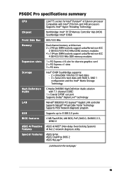
P5GDC Pro specifications summary CPU Chipset Front Side Bus Memory Expansion slots Storage High Definition Audio LAN USB BIOS features ASUS AI Proactive Features Special features LGA775 socket for Intel® Pentium® 4/Celeron processor Compatible with Intel®... Cable Tester Technology Supports POST Network diagnostic program Supports up to 8 USB 2.0 ports 4 MB Flash ROM, AMI BIOS, PnP, DMI2.0, SM BIOS 2.3, WfM2.0 ASUS AI NOS™ (Non-delay Overclocking System) AI Net 2 network diagnosis utility ASUS Q-Fan ASUS CrashFree BIOS 2 ASUS MyLogo™ (continued on the next page) ix
P5GDC Pro specifications summary CPU Chipset Front Side Bus Memory Expansion slots Storage High Definition Audio LAN USB BIOS features ASUS AI Proactive Features Special features LGA775 socket for Intel® Pentium® 4/Celeron processor Compatible with Intel®... Cable Tester Technology Supports POST Network diagnostic program Supports up to 8 USB 2.0 ports 4 MB Flash ROM, AMI BIOS, PnP, DMI2.0, SM BIOS 2.3, WfM2.0 ASUS AI NOS™ (Non-delay Overclocking System) AI Net 2 network diagnosis utility ASUS Q-Fan ASUS CrashFree BIOS 2 ASUS MyLogo™ (continued on the next page) ix
User Manual
Page 16
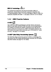
... the LAN cable(s) and reports shorts and faults up to the LAN (RJ-45) port(s). AI NOS™ (Non-Delay Overclocking System) The ASUS Non-delay Overclocking System™ (NOS) is backward compatible with USB 1.1. With this utility, you can easily monitor the condition of the Ethernet cable...(s) connected to 100 meters at 1 meter accuracy. See page 4-21 for details. 1.3.2 ASUS Proactive features AI NET2 The Ai NET2 is a BIOS-based diagnostic tool that auto-detects the CPU loading and dynamically overclocks the CPU speed only when needed. See page 5-10...
... the LAN cable(s) and reports shorts and faults up to the LAN (RJ-45) port(s). AI NOS™ (Non-Delay Overclocking System) The ASUS Non-delay Overclocking System™ (NOS) is backward compatible with USB 1.1. With this utility, you can easily monitor the condition of the Ethernet cable...(s) connected to 100 meters at 1 meter accuracy. See page 4-21 for details. 1.3.2 ASUS Proactive features AI NET2 The Ai NET2 is a BIOS-based diagnostic tool that auto-detects the CPU loading and dynamically overclocks the CPU speed only when needed. See page 5-10...
User Manual
Page 17
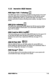
...DOS-based utility or boot from the support CD in case when the BIOS codes and data are corrupted. See page 4-5 for details. 1.3.3 Innovative ASUS features ASUS Hyper Path 2 Technology The ASUS Hyper Path 2 technology optimizes the full potential of the Intel® ...chipset by shortening the latency time between the CPU and the system memory. ASUS EZ Flash BIOS With the ASUS EZ Flash, you to personalize and add style to buy a replacement ROM chip. ASUS P5GDC Pro...
...DOS-based utility or boot from the support CD in case when the BIOS codes and data are corrupted. See page 4-5 for details. 1.3.3 Innovative ASUS features ASUS Hyper Path 2 Technology The ASUS Hyper Path 2 technology optimizes the full potential of the Intel® ...chipset by shortening the latency time between the CPU and the system memory. ASUS EZ Flash BIOS With the ASUS EZ Flash, you to personalize and add style to buy a replacement ROM chip. ASUS P5GDC Pro...
User Manual
Page 28
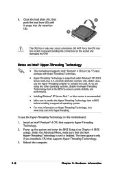
...on this motherboard: 1. Notes on Intel® Hyper-Threading Technology • This motherboard supports Intel® Pentium® 4 CPUs in BIOS before installing a supported operating system. • For more information on Hyper-Threading Technology, visit www.intel.com/info/hyperthreading. Power up ...the system and enter the BIOS Setup (see Chapter 4: BIOS setup). DO NOT force the CPU into the retention tab. Under the Advanced Menu, make sure that the item ...
...on this motherboard: 1. Notes on Intel® Hyper-Threading Technology • This motherboard supports Intel® Pentium® 4 CPUs in BIOS before installing a supported operating system. • For more information on Hyper-Threading Technology, visit www.intel.com/info/hyperthreading. Power up ...the system and enter the BIOS Setup (see Chapter 4: BIOS setup). DO NOT force the CPU into the retention tab. Under the Advanced Menu, make sure that the item ...
User Manual
Page 41
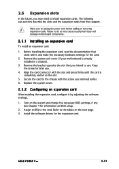
... to use . 4. Keep the screw for information on the system and change the necessary BIOS settings, if any. Install the software drivers for the card. 2. Secure the card to install expansion cards. See Chapter 4 for later use . ASUS P5GDC Pro 2-21 Remove the bracket opposite the slot that you intend to unplug the power... system cover. 2.5.2 Configuring an expansion card After installing the expansion card, configure it and make the necessary hardware settings for the expansion card. Turn on BIOS setup. 2.
... to use . 4. Keep the screw for information on the system and change the necessary BIOS settings, if any. Install the software drivers for the card. 2. Secure the card to install expansion cards. See Chapter 4 for later use . ASUS P5GDC Pro 2-21 Remove the bracket opposite the slot that you intend to unplug the power... system cover. 2.5.2 Configuring an expansion card After installing the expansion card, configure it and make the necessary hardware settings for the expansion card. Turn on BIOS setup. 2.

User Manual
Page 44
... Parameter Recall) feature. Hold down and reboot the system so the BIOS can clear the CMOS memory of date, time, and system setup parameters by erasing the CMOS RTC RAM data. 2.6 Jumpers 1. P5GDC PRO CLRTC1 12 23 Normal (Default) P5GDC PRO Clear RTC RAM Clear CMOS You do not need to clear the ...RTC when the system hangs due to re-enter data. Shut down the key during the boot process and enter BIOS setup to overclocking. To erase the...
... Parameter Recall) feature. Hold down and reboot the system so the BIOS can clear the CMOS memory of date, time, and system setup parameters by erasing the CMOS RTC RAM data. 2.6 Jumpers 1. P5GDC PRO CLRTC1 12 23 Normal (Default) P5GDC PRO Clear RTC RAM Clear CMOS You do not need to clear the ...RTC when the system hangs due to re-enter data. Shut down the key during the boot process and enter BIOS setup to overclocking. To erase the...

User Manual
Page 46
This feature requires an ATX power supply that can supply at least 1A on the keyboard (the default is the Space Bar). P5GDC PRO KBPWR1 12 23 +5V +5VSB (Default) P5GDC PRO Keyboard power setting 2-26 Chapter 2: Hardware information Keyboard power (3-pin KBPWR) This jumper allows you press a key on the +5VSB lead, and a corresponding setting in the BIOS. 3. Set this jumper to pins 2-3 (+5VSB) to wake up the computer when you to enable or disable the keyboard wake-up feature.
This feature requires an ATX power supply that can supply at least 1A on the keyboard (the default is the Space Bar). P5GDC PRO KBPWR1 12 23 +5V +5VSB (Default) P5GDC PRO Keyboard power setting 2-26 Chapter 2: Hardware information Keyboard power (3-pin KBPWR) This jumper allows you press a key on the +5VSB lead, and a corresponding setting in the BIOS. 3. Set this jumper to pins 2-3 (+5VSB) to wake up the computer when you to enable or disable the keyboard wake-up feature.
User Manual
Page 51
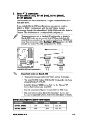
...ATA Master/Slave connectors Connector Color Setting SATA1, SATA2 Red Master SATA3, SATA4 Black Slave Use Boot Disk Data Disk ASUS P5GDC Pro 2-31 P5GDC PRO SATA3 SATA4 GND RSATA_TXP4 RSATA_TXN4 GND RSATA_RXP4 RSATA_RXN4 GND GND RSATA_TXP3 RSATA_TXN3 GND RSATA_RXP3 RSATA_RXN3 GND SATA1 SATA2 GND RSATA_TXP2 RSATA_TXN2...disk drives to the table below for each RAID 0 or RAID 1 set the C o n f i g u r e S A T A A s item in the BIOS to support S3 function. If you installed Serial ATA hard disk drives, you intend to create a Serial ATA RAID set to Chapter 5 for information on...
...ATA Master/Slave connectors Connector Color Setting SATA1, SATA2 Red Master SATA3, SATA4 Black Slave Use Boot Disk Data Disk ASUS P5GDC Pro 2-31 P5GDC PRO SATA3 SATA4 GND RSATA_TXP4 RSATA_TXN4 GND RSATA_RXP4 RSATA_RXN4 GND GND RSATA_TXP3 RSATA_TXN3 GND RSATA_RXP3 RSATA_RXN3 GND SATA1 SATA2 GND RSATA_TXP2 RSATA_TXN2...disk drives to the table below for each RAID 0 or RAID 1 set the C o n f i g u r e S A T A A s item in the BIOS to support S3 function. If you installed Serial ATA hard disk drives, you intend to create a Serial ATA RAID set to Chapter 5 for information on...

User Manual
Page 57
... Connect one end of the motherboard's high-definition audio capability. • By default, this connector is for details. P5GDC PRO GND PRESENCE# SENSE1_RETUR SENSE2_RETUR Azalia-compliant pin definition Legacy AC'97-compliant pin definition AGND NC NC NC AAFP MIC2 MICPWR...module to this connector. ASUS P5GDC Pro 2-37 See page 4-27 for a chassis-mounted front panel audio I /O module cable to this connector, set to [Azalia]. Front panel audio connector (10-1 pin AAFP) This connector is set the F r o n t P a n e l S u p p o r t T y p e item in the BIOS setup to legacy AC`...
... Connect one end of the motherboard's high-definition audio capability. • By default, this connector is for details. P5GDC PRO GND PRESENCE# SENSE1_RETUR SENSE2_RETUR Azalia-compliant pin definition Legacy AC'97-compliant pin definition AGND NC NC NC AAFP MIC2 MICPWR...module to this connector. ASUS P5GDC Pro 2-37 See page 4-27 for a chassis-mounted front panel audio I /O module cable to this connector, set to [Azalia]. Front panel audio connector (10-1 pin AAFP) This connector is set the F r o n t P a n e l S u p p o r t T y p e item in the BIOS setup to legacy AC`...

User Manual
Page 58
...the HDD. • System warning speaker (Orange 4-pin SPEAKER) This 4-pin connector is for the HDD Activity LED. PWR Ground Reset Ground IDE_LED P5GDC PRO System panel connector Reset PWRSW The sytem panel connector is for the system power LED. The speaker allows you turn on the system power, and... blinks when the system is in SLEEP or SOFT-OFF mode depending on the BIOS settings. Connect the chassis power LED cable to this connector. Connect the HDD Activity LED cable to this connector. The system power LED ...
...the HDD. • System warning speaker (Orange 4-pin SPEAKER) This 4-pin connector is for the HDD Activity LED. PWR Ground Reset Ground IDE_LED P5GDC PRO System panel connector Reset PWRSW The sytem panel connector is for the system power LED. The speaker allows you turn on the system power, and... blinks when the system is in SLEEP or SOFT-OFF mode depending on the BIOS settings. Connect the chassis power LED cable to this connector. Connect the HDD Activity LED cable to this connector. The system power LED ...

User Manual
Page 61
...6. The system then runs the power-on the system front panel case lights up when you do not see BIOS beep codes table below) or additional messages appear on test. ASUS P5GDC Pro 3-1 External SCSI devices (starting with a surge protector. 5. If you press the ATX power button. Follow the... error No master drive detected Floppy controller failure Hardware component failure 7. Turn on the chain) c. Connect the power cord to enter the BIOS Setup. Be sure that is equipped with the last device on the devices in Chapter 4. Monitor b. After applying power, the system power...
...6. The system then runs the power-on the system front panel case lights up when you do not see BIOS beep codes table below) or additional messages appear on test. ASUS P5GDC Pro 3-1 External SCSI devices (starting with a surge protector. 5. If you press the ATX power button. Follow the... error No master drive detected Floppy controller failure Hardware component failure 7. Turn on the chain) c. Connect the power cord to enter the BIOS Setup. Be sure that is equipped with the last device on the devices in Chapter 4. Monitor b. After applying power, the system power...
User Manual
Page 62
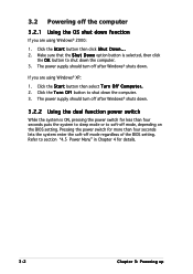
... o w n option button is ON, pressing the power switch for less than four seconds lets the system enter the soft-off mode regardless of the BIOS setting. Refer to shut down the computer. 3. Pressing the power switch for details. 3-2 Chapter 3: Powering up The power supply should turn off after ... shuts down. 3.2.2 Using the dual function power switch While the system is selected, then click the O K button to soft-off mode, depending on the BIOS setting. Click the T u r n O f f button to section "4.5 Power Menu" in Chapter 4 for more than four seconds puts the system to...
... o w n option button is ON, pressing the power switch for less than four seconds lets the system enter the soft-off mode regardless of the BIOS setting. Refer to shut down the computer. 3. Pressing the power switch for details. 3-2 Chapter 3: Powering up The power supply should turn off after ... shuts down. 3.2.2 Using the dual function power switch While the system is selected, then click the O K button to soft-off mode, depending on the BIOS setting. Click the T u r n O f f button to section "4.5 Power Menu" in Chapter 4 for more than four seconds puts the system to...

User Manual
Page 63
This chapter tells how to change the system settings through the BIOS Setup menus. Detailed descriptions of the BIOS parameters are also provided. 4 BIOS setup
This chapter tells how to change the system settings through the BIOS Setup menus. Detailed descriptions of the BIOS parameters are also provided. 4 BIOS setup

User Manual
Page 64
Chapter summary 4 4.1 Managing and updating your BIOS 4-1 4.2 BIOS setup program 4-10 4.3 Main menu 4-13 4.4 Advanced menu 4-18 4.5 Power menu 4-31 4.6 Boot menu 4-36 4.7 Exit menu 4-40 ASUS P5GDC Pro
Chapter summary 4 4.1 Managing and updating your BIOS 4-1 4.2 BIOS setup program 4-10 4.3 Main menu 4-13 4.4 Advanced menu 4-18 4.5 Power menu 4-31 4.6 Boot menu 4-36 4.7 Exit menu 4-40 ASUS P5GDC Pro
User Manual
Page 65
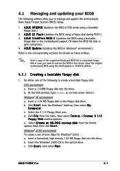
... drive. Windows® 2000 environment To create a set of the original motherboard BIOS file to a bootable floppy disk in the future. A S U S A F U D O S (Updates the BIOS in Windows® environment.) Refer to manage and update the motherboard Basic Input/Output System (BIOS) setup. 1. Insert a 1.44MB floppy disk into the drive. Windows® XP environment a. Select C r e a t e a n M S - ASUS P5GDC Pro 4-1 c.
... drive. Windows® 2000 environment To create a set of the original motherboard BIOS file to a bootable floppy disk in the future. A S U S A F U D O S (Updates the BIOS in Windows® environment.) Refer to manage and update the motherboard Basic Input/Output System (BIOS) setup. 1. Insert a 1.44MB floppy disk into the drive. Windows® XP environment a. Select C r e a t e a n M S - ASUS P5GDC Pro 4-1 c.

User Manual
Page 66
... so it is not found !" error message appears if the correct BIOS file is accessible by pressing + during POST to P5GDCP.ROM. 4-2 Chapter 4: BIOS setup Visit the ASUS website (www.asus.com) to download the latest BIOS file for the motherboard and rename the same to prevent system boot failure...! • A "Floppy not found!" When the correct BIOS file is built-in the drive. d. ...
... so it is not found !" error message appears if the correct BIOS file is accessible by pressing + during POST to P5GDCP.ROM. 4-2 Chapter 4: BIOS setup Visit the ASUS website (www.asus.com) to download the latest BIOS file for the motherboard and rename the same to prevent system boot failure...! • A "Floppy not found!" When the correct BIOS file is built-in the drive. d. ...

User Manual
Page 67
... the AFUDOS utility (afudos.exe) from the motherboard support CD to the floppy disk. Press . Version 1.10 Copyright (C) 2002 American Megatrends, Inc. ASUS P5GDC Pro 4-3 The utility copies the current BIOS file to the bootable floppy disk you created earlier. 2. A:\>afudos /oOLDBIOS1.ROM AMI Firmware Update Utility - All rights reserved. 4.1.3 AFUDOS utility The AFUDOS...
... the AFUDOS utility (afudos.exe) from the motherboard support CD to the floppy disk. Press . Version 1.10 Copyright (C) 2002 American Megatrends, Inc. ASUS P5GDC Pro 4-3 The utility copies the current BIOS file to the bootable floppy disk you created earlier. 2. A:\>afudos /oOLDBIOS1.ROM AMI Firmware Update Utility - All rights reserved. 4.1.3 AFUDOS utility The AFUDOS...

User Manual
Page 68
... .... The utility reads the file and starts updating the BIOS. Version 1.19(ASUS V2.07(03.11.24BB)) Copyright (C) 2003 American Megatrends, Inc. Updating the BIOS file To update the BIOS file using the AFUDOS utility: 1. Visit the ASUS website (www.asus.com) and download the latest BIOS file for the motherboard. You need to the bootable...
... .... The utility reads the file and starts updating the BIOS. Version 1.19(ASUS V2.07(03.11.24BB)) Copyright (C) 2003 American Megatrends, Inc. Updating the BIOS file To update the BIOS file using the AFUDOS utility: 1. Visit the ASUS website (www.asus.com) and download the latest BIOS file for the motherboard. You need to the bootable...

User Manual
Page 69
...the floppy disk containing the updated motherboard BIOS before using this utility. • Make sure that allows you rename the original or updated BIOS file in the floppy disk to the floppy disk drive. Turn on the system. 2. ASUS P5GDC Pro 4-5 done Writing flash ..... R O... M. Insert the floppy disk with the original or updated BIOS file to P 5 G D C P . Version 1.19(ASUS V2.07(03.11.24BB)) Copyright (C) 2003 American Megatrends, Inc. Reboot the ...
...the floppy disk containing the updated motherboard BIOS before using this utility. • Make sure that allows you rename the original or updated BIOS file in the floppy disk to the floppy disk drive. Turn on the system. 2. ASUS P5GDC Pro 4-5 done Writing flash ..... R O... M. Insert the floppy disk with the original or updated BIOS file to P 5 G D C P . Version 1.19(ASUS V2.07(03.11.24BB)) Copyright (C) 2003 American Megatrends, Inc. Reboot the ...


