
P5GD1-VM User's manual English Edition E1881
Page 3
Contents Notices vi Safety information vii P5GD1-VM specifications summary viii Chapter 1: Product introduction 1.1 Welcome 1-2 1.2 Package contents 1-2 1.3 Special features 1-2 1.3.1 Product highlights 1-2 1.3.2 Innovative ASUS features 1-4 1.4 Before you proceed 1-5 1.5 Motherboard overview 1-6 1.5.1 Motherboard layout 1-6 1.5.2 Placement direction 1-7 1.5.3 Screw holes 1-7 1.6 Central Processing Unit (CPU 1-8 1.6.1 Installing the CPU 1-8 1.6.2 Installing the CPU heatsink and fan 1-11 1.6.3 Uninstalling the CPU heatsink and fan 1-13 1.7 System memory...
Contents Notices vi Safety information vii P5GD1-VM specifications summary viii Chapter 1: Product introduction 1.1 Welcome 1-2 1.2 Package contents 1-2 1.3 Special features 1-2 1.3.1 Product highlights 1-2 1.3.2 Innovative ASUS features 1-4 1.4 Before you proceed 1-5 1.5 Motherboard overview 1-6 1.5.1 Motherboard layout 1-6 1.5.2 Placement direction 1-7 1.5.3 Screw holes 1-7 1.6 Central Processing Unit (CPU 1-8 1.6.1 Installing the CPU 1-8 1.6.2 Installing the CPU heatsink and fan 1-11 1.6.3 Uninstalling the CPU heatsink and fan 1-13 1.7 System memory...

P5GD1-VM User's manual English Edition E1881
Page 4
...Chapter 2: BIOS setup 2.1 Managing and updating your BIOS 2-2 2.1.1 Creating a bootable floppy disk 2-2 2.1.2 AFUDOS utility 2-3 2.1.3 ASUS EZ Flash utility 2-5 2.1.4 ASUS CrashFree BIOS 2 utility 2-7 2.1.5 ASUS Update utility 2-9 2.2 BIOS setup program 2-12 2.2.1 BIOS menu screen 2-13 2.2.2 Menu bar 2-13 2.2.3 Navigation keys 2-13... Master/Slave ........ 2-16 2.3.5 IDE Configuration 2-17 2.3.6 System Information 2-18 2.4 Advanced menu 2-19 2.4.1 USB Configuration 2-19 2.4.2 CPU Configuration 2-20 2.4.3 Chipset 2-22 2.4.4 Onboard Devices Configuration 2-24 2.4.5 PCI PnP 2-25 iv
...Chapter 2: BIOS setup 2.1 Managing and updating your BIOS 2-2 2.1.1 Creating a bootable floppy disk 2-2 2.1.2 AFUDOS utility 2-3 2.1.3 ASUS EZ Flash utility 2-5 2.1.4 ASUS CrashFree BIOS 2 utility 2-7 2.1.5 ASUS Update utility 2-9 2.2 BIOS setup program 2-12 2.2.1 BIOS menu screen 2-13 2.2.2 Menu bar 2-13 2.2.3 Navigation keys 2-13... Master/Slave ........ 2-16 2.3.5 IDE Configuration 2-17 2.3.6 System Information 2-18 2.4 Advanced menu 2-19 2.4.1 USB Configuration 2-19 2.4.2 CPU Configuration 2-20 2.4.3 Chipset 2-22 2.4.4 Onboard Devices Configuration 2-24 2.4.5 PCI PnP 2-25 iv

P5GD1-VM User's manual English Edition E1881
Page 5
... Configuration 2-32 2.6.3 Security 2-33 2.7 Exit menu 2-35 Chapter 3: Software support 3.1 Installing an operating system 3-2 3.2 Support CD information 3-2 3.2.1 Running the support CD 3-2 3.2.2 Drivers menu 3-3 3.2.3 Utilities menu 3-4 3.2.4 ASUS Contact information 3-5 3.2.5 Other information 3-6 Appendix: CPU features A.1 Intel® EM64T A-2 A.2 Enhanced Intel SpeedStep® Technology (EIST A-2 A.2.1 System requirements A-2 A.2.2 Using the EIST A-3 A.3 Intel® Hyper-Threading Technology A-4 v
... Configuration 2-32 2.6.3 Security 2-33 2.7 Exit menu 2-35 Chapter 3: Software support 3.1 Installing an operating system 3-2 3.2 Support CD information 3-2 3.2.1 Running the support CD 3-2 3.2.2 Drivers menu 3-3 3.2.3 Utilities menu 3-4 3.2.4 ASUS Contact information 3-5 3.2.5 Other information 3-6 Appendix: CPU features A.1 Intel® EM64T A-2 A.2 Enhanced Intel SpeedStep® Technology (EIST A-2 A.2.1 System requirements A-2 A.2.2 Using the EIST A-3 A.3 Intel® Hyper-Threading Technology A-4 v

P5GD1-VM User's manual English Edition E1881
Page 9
ix P5GD1-VM specifications summary Rear panel Internal connectors Power requirement 1 x PS/2 mouse port 1 x Parallel port 1 x LAN (RJ-45) port 8-channel audio ports 4 x USB 2.0 ports 1 x VGA port 1 x Serial port 1 x PS/2 keyboard port 1 x Floppy disk drive connector 1 x Primary IDE connector 1 x PCI IDE connector 4 x Serial ATA connectors 1 x CPU fan connector ... factor Support CD contents Micro ATX form factor: 9.6 in x 9.6 in (24.5 cm x 24.4 cm) Device drivers ASUS PC Probe ASUS Live Update Utility Anti-virus software (OEM version) *Specifications are subject to change without notice.
ix P5GD1-VM specifications summary Rear panel Internal connectors Power requirement 1 x PS/2 mouse port 1 x Parallel port 1 x LAN (RJ-45) port 8-channel audio ports 4 x USB 2.0 ports 1 x VGA port 1 x Serial port 1 x PS/2 keyboard port 1 x Floppy disk drive connector 1 x Primary IDE connector 1 x PCI IDE connector 4 x Serial ATA connectors 1 x CPU fan connector ... factor Support CD contents Micro ATX form factor: 9.6 in x 9.6 in (24.5 cm x 24.4 cm) Device drivers ASUS PC Probe ASUS Live Update Utility Anti-virus software (OEM version) *Specifications are subject to change without notice.
P5GD1-VM User's manual English Edition E1881
Page 13
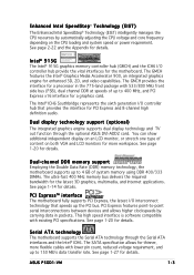
... the required bandwidth for more flexible cables with existing PCI specifications. See page 1-14 for enhanced 3D, 2D, and video capabilities. ASUS P5GD1-VM 1-3 You can show additional independent display on the CPU loading and system speed or power requirement. Intel® 915G The Intel® 915G graphics memory controller hub (GMCH) and the...
... the required bandwidth for more flexible cables with existing PCI specifications. See page 1-14 for enhanced 3D, 2D, and video capabilities. ASUS P5GD1-VM 1-3 You can show additional independent display on the CPU loading and system speed or power requirement. Intel® 915G The Intel® 915G graphics memory controller hub (GMCH) and the...

P5GD1-VM User's manual English Edition E1881
Page 18
... socket contacts are not bent. ASUS will process Return Merchandise Authorization (RMA) requests only if the motherboard comes with the cap on the LGA775 socket. • The product warranty does not cover damage to the PnP cap/socket contacts/motherboard components. P5GD1-VM ® P5GD1-VM Socket 775 Before installing the CPU, make sure that the...
... socket contacts are not bent. ASUS will process Return Merchandise Authorization (RMA) requests only if the motherboard comes with the cap on the LGA775 socket. • The product warranty does not cover damage to the PnP cap/socket contacts/motherboard components. P5GD1-VM ® P5GD1-VM Socket 775 Before installing the CPU, make sure that the...

P5GD1-VM User's manual English Edition E1881
Page 19
To prevent damage to a B 100º angle (A), then push the PnP cap from the retention tab. Position the CPU over the socket, making sure that the gold triangle is released from the load plate window to remove (B). Load plate 5. Press the...cap B This side of the arrow to the left (B) until it to a 135º angle. 4. 2. Gold triangle mark ASUS P5GD1-VM A 1-9 The socket alignment key A l i g n m e n t k e y should face you are installing a CPU. 3. Lift the load plate with your thumb and forefinger to the socket pins, do not remove the PnP cap unless you ...
To prevent damage to a B 100º angle (A), then push the PnP cap from the retention tab. Position the CPU over the socket, making sure that the gold triangle is released from the load plate window to remove (B). Load plate 5. Press the...cap B This side of the arrow to the left (B) until it to a 135º angle. 4. 2. Gold triangle mark ASUS P5GD1-VM A 1-9 The socket alignment key A l i g n m e n t k e y should face you are installing a CPU. 3. Lift the load plate with your thumb and forefinger to the socket pins, do not remove the PnP cap unless you ...

P5GD1-VM User's manual English Edition E1881
Page 20
Refer to prevent bending the connectors on these CPU features. 1-10 Chapter 1: Product introduction Close the load plate (A), then A push the load lever (B) until it snaps into the socket to the Appendix for more information on the socket and damaging the CPU! 6. The CPU fits in only one correct orientation. B The motherboard supports Intel® Pentium® 4 LGA775 processors with the Intel® Enhanced Memory 64 Technology (EM64T), Enhanced Intel SpeedStep® Technology (EIST), and Hyper-Threading Technology. DO NOT force the CPU into the retention tab.
Refer to prevent bending the connectors on these CPU features. 1-10 Chapter 1: Product introduction Close the load plate (A), then A push the load lever (B) until it snaps into the socket to the Appendix for more information on the socket and damaging the CPU! 6. The CPU fits in only one correct orientation. B The motherboard supports Intel® Pentium® 4 LGA775 processors with the Intel® Enhanced Memory 64 Technology (EM64T), Enhanced Intel SpeedStep® Technology (EIST), and Hyper-Threading Technology. DO NOT force the CPU into the retention tab.
P5GD1-VM User's manual English Edition E1881
Page 21
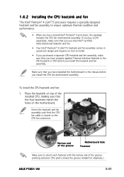
Narrow end of the groove Motherboard hole Fastener Make sure to the chassis before you have properly applied Thermal Interface Material to the CPU fan connector. Place the heatsink on the motherboard. Make sure that you install the heatsink and fan assembly. If you buy a ... you have installed the motherboard to orient each fastener with the narrow end of the installed CPU, making sure that the four fasteners match the holes on top of the groove pointing outward. (The photo shows the groove shaded for emphasis.) ASUS P5GD1-VM 1-11 To install the CPU heatsink and fan: 1.
Narrow end of the groove Motherboard hole Fastener Make sure to the chassis before you have properly applied Thermal Interface Material to the CPU fan connector. Place the heatsink on the motherboard. Make sure that you install the heatsink and fan assembly. If you buy a ... you have installed the motherboard to orient each fastener with the narrow end of the installed CPU, making sure that the four fasteners match the holes on top of the groove pointing outward. (The photo shows the groove shaded for emphasis.) ASUS P5GD1-VM 1-11 To install the CPU heatsink and fan: 1.
P5GD1-VM User's manual English Edition E1881
Page 22
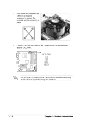
Connect the CPU fan cable to connect the CPU fan connector! 2. A B A B B A 3. CPU_FAN1 P5GD1-VM GND CPU FAN PWR CPU FAN IN CPU FAN PWM ® Do not forget to the connector on the motherboard labeled CPU_FAN1. Hardware monitoring errors can occur if you fail to secure the B heatsink and fan assembly in a diagonal sequence to plug this connector. 1-12 Chapter 1: Product introduction Push down two fasteners at a time in A place.
Connect the CPU fan cable to connect the CPU fan connector! 2. A B A B B A 3. CPU_FAN1 P5GD1-VM GND CPU FAN PWR CPU FAN IN CPU FAN PWM ® Do not forget to the connector on the motherboard labeled CPU_FAN1. Hardware monitoring errors can occur if you fail to secure the B heatsink and fan assembly in a diagonal sequence to plug this connector. 1-12 Chapter 1: Product introduction Push down two fasteners at a time in A place.

P5GD1-VM User's manual English Edition E1881
Page 23
Rotate each fastener counterclockwise. 3. Pull up two fasteners at a time in a diagonal sequence to disengage the heatsink B and fan assembly from the connector on the motherboard. 2. Disconnect the CPU fan cable from the A motherboard. A B A B B A ASUS P5GD1-VM 1-13 1.6.3 Uninstalling the CPU heatsink and fan To uninstall the CPU heatsink and fan: 1.
Rotate each fastener counterclockwise. 3. Pull up two fasteners at a time in a diagonal sequence to disengage the heatsink B and fan assembly from the connector on the motherboard. 2. Disconnect the CPU fan cable from the A motherboard. A B A B B A ASUS P5GD1-VM 1-13 1.6.3 Uninstalling the CPU heatsink and fan To uninstall the CPU heatsink and fan: 1.

P5GD1-VM User's manual English Edition E1881
Page 32
USBPW12 USBPW34 2 1 +5V (Default) 3 2 +5VSB P5GD1-VM USBPW56 ® USBPW78 12 23 +5V P5GD1-VM USB device wake-up (Default) +5VSB • The USB device wake-up the computer from S3 and S4 sleep modes (no power to CPU, DRAM in slow refresh, power supply in sleep mode. 3. Keyboard power (3-pin KBPWR1) This jumper allows you...
USBPW12 USBPW34 2 1 +5V (Default) 3 2 +5VSB P5GD1-VM USBPW56 ® USBPW78 12 23 +5V P5GD1-VM USB device wake-up (Default) +5VSB • The USB device wake-up the computer from S3 and S4 sleep modes (no power to CPU, DRAM in slow refresh, power supply in sleep mode. 3. Keyboard power (3-pin KBPWR1) This jumper allows you...

P5GD1-VM User's manual English Edition E1881
Page 33
... 1-2 (Default) if you are using a 3-pin CPU fan. Fan power (3-pin FANPWR1) Set this jumper to 2-3 if you are using a 4-pin CPU fan. Set this jumper to a Local Area Network (LAN) through a network hub. P S / 2 m o u s e p o r t ( g r e e n ) . L A N ( R J - 4 5 ) p o r t . This port is for a PS/2 mouse. 2 . This 25-pin port connects a parallel printer, a scanner, or other devices. 3 . ASUS P5GD1-VM 1-23 4.
... 1-2 (Default) if you are using a 3-pin CPU fan. Fan power (3-pin FANPWR1) Set this jumper to 2-3 if you are using a 4-pin CPU fan. Set this jumper to a Local Area Network (LAN) through a network hub. P S / 2 m o u s e p o r t ( g r e e n ) . L A N ( R J - 4 5 ) p o r t . This port is for a PS/2 mouse. 2 . This 25-pin port connects a parallel printer, a scanner, or other devices. 3 . ASUS P5GD1-VM 1-23 4.

P5GD1-VM User's manual English Edition E1881
Page 38
...connect the fan cables to the fan connectors on the fan connectors! P5GD1-VM GND +12V Rotation GND CPU FAN PWR CPU FAN IN CPU FAN PWM 1-28 Chapter 1: Product introduction These are not jumpers! See page 1-22 for details. CPU and Chassis Fan connectors (4-pin CPU_FAN1, 3-pin CHA_FAN1) The fan ... connectors. Do not place jumper caps on the motherboard, making sure that your Fan Power (FANPWR1) jumper setting is correct. CHA_FAN1 CPU_FAN1 ® P5GD1-VM Fan connectors Make sure that the black wire of each cable matches the ground pin of 1 A~2.22 A (26.64 W max.) at +12V...
...connect the fan cables to the fan connectors on the fan connectors! P5GD1-VM GND +12V Rotation GND CPU FAN PWR CPU FAN IN CPU FAN PWM 1-28 Chapter 1: Product introduction These are not jumpers! See page 1-22 for details. CPU and Chassis Fan connectors (4-pin CPU_FAN1, 3-pin CHA_FAN1) The fan ... connectors. Do not place jumper caps on the motherboard, making sure that your Fan Power (FANPWR1) jumper setting is correct. CHA_FAN1 CPU_FAN1 ® P5GD1-VM Fan connectors Make sure that the black wire of each cable matches the ground pin of 1 A~2.22 A (26.64 W max.) at +12V...
P5GD1-VM User's manual English Edition E1881
Page 40
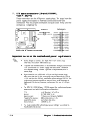
ATX12V1 EATXPWR1 P5GD1-VM GND +12V DC ® P5GD1-VM ATX power connectors GND +3 Volts +12V DC +12 Volts +12 Volts +5V Standby Power OK Ground +5 Volts Ground +5 Volts Ground +3 Volts +3 Volts Ground +5 Volts +5 Volts +5 ... has a minimum power rating of a 20-pin PSU. • The ATX 12 V 350 W Spec. 2.0 PSU passed the motherboard power requirement test with the following configuration: CPU : Memory : Grpahics card : Parallel ATA devices : Serial ATA device : Optical drives : Intel® Pentium® 4 3.6 GHz 512 MB DDR2 (x 4) PCI Express x16 Nvidia EN5900 IDE...
ATX12V1 EATXPWR1 P5GD1-VM GND +12V DC ® P5GD1-VM ATX power connectors GND +3 Volts +12V DC +12 Volts +12 Volts +5V Standby Power OK Ground +5 Volts Ground +5 Volts Ground +3 Volts +3 Volts Ground +5 Volts +5 Volts +5 ... has a minimum power rating of a 20-pin PSU. • The ATX 12 V 350 W Spec. 2.0 PSU passed the motherboard power requirement test with the following configuration: CPU : Memory : Grpahics card : Parallel ATA devices : Serial ATA device : Optical drives : Intel® Pentium® 4 3.6 GHz 512 MB DDR2 (x 4) PCI Express x16 Nvidia EN5900 IDE...
P5GD1-VM User's manual English Edition E1881
Page 62
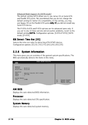
...] Selects the time out value for advanced users only. AMIBIOS Version : 08.00.10 Build Date : 06/10/04 Processor Type Speed Count : Genuine Intel(R) CPU 3.20GHz : 3200 MHz : 1 System Memory Size : 248MB AMI BIOS Displays the auto-detected BIOS information. System Memory Displays the auto-detected system memory. 2-18 Chapter... an overview of these options and encounter problems, revert to use legacy OS on Serial ATA and Parallel ATA ports. Processor Displays the auto-detected CPU specification.
...] Selects the time out value for advanced users only. AMIBIOS Version : 08.00.10 Build Date : 06/10/04 Processor Type Speed Count : Genuine Intel(R) CPU 3.20GHz : 3200 MHz : 1 System Memory Size : 248MB AMI BIOS Displays the auto-detected BIOS information. System Memory Displays the auto-detected system memory. 2-18 Chapter... an overview of these options and encounter problems, revert to use legacy OS on Serial ATA and Parallel ATA ports. Processor Displays the auto-detected CPU specification.

P5GD1-VM User's manual English Edition E1881
Page 63
... Mode [Enabled] [Auto] [Enabled] [HiSpeed] Enables USB host controllers. If no USB device is detected, the item shows None. Configuration options: [Disabled] [Enabled] ASUS P5GD1-VM 2-19 USB Configuration CPU Configuration Chipset Onboard Devices Configuration PCI PnP Configure the USB support. 2.4.1 USB Configuration The items in this menu allows you to change the USB...
... Mode [Enabled] [Auto] [Enabled] [HiSpeed] Enables USB host controllers. If no USB device is detected, the item shows None. Configuration options: [Disabled] [Enabled] ASUS P5GD1-VM 2-19 USB Configuration CPU Configuration Chipset Onboard Devices Configuration PCI PnP Configure the USB support. 2.4.1 USB Configuration The items in this menu allows you to change the USB...

P5GD1-VM User's manual English Edition E1881
Page 64
...or Full Speed (12 Mbps). If no USB device is detected, the legacy USB support is set in this menu show the CPU-related information that the BIOS automatically detects. NOTE: If an invalid ratio is disabled. If detected, the USB controller legacy mode ... [ 8] VID CMOS Setting: [ 62] Microcode Updation: [Enabled] Max CPUID Value Limit: [Disabled] Enhanced C1 Control [Auto] CPU Internal Thermal Control [Auto] Sets the ratio between CPU Core Clock and the FSB Frequency. Configuration options: [Disabled] [Enabled] [Auto] USB 2.0 Controller [Enabled] Allows you to enable ...
...or Full Speed (12 Mbps). If no USB device is detected, the legacy USB support is set in this menu show the CPU-related information that the BIOS automatically detects. NOTE: If an invalid ratio is disabled. If detected, the USB controller legacy mode ... [ 8] VID CMOS Setting: [ 62] Microcode Updation: [Enabled] Max CPUID Value Limit: [Disabled] Enhanced C1 Control [Auto] CPU Internal Thermal Control [Auto] Sets the ratio between CPU Core Clock and the FSB Frequency. Configuration options: [Disabled] [Enabled] [Auto] USB 2.0 Controller [Enabled] Allows you to enable ...

P5GD1-VM User's manual English Edition E1881
Page 65
...Configuration options: [Auto] [Disabled] Hyper Threading Technology [Enabled] Allows you to set to [Auto], the BIOS will automatically check the CPU's capability to run. Configuration options: [Disabled] [Enabled] Max CPUID Value Limit [Disabled] Enable this item to adjust the values. Microcode...between the CPU Core Clock and the Front Side Bus frequency. Use the < + > or < - > keys to the Appendix for more information on the Hyper-Threading Technology. The default value of this item is to enable the C1E support. Configuration options: [Disabled] [Enabled] ASUS P5GD1-VM 2-21...
...Configuration options: [Auto] [Disabled] Hyper Threading Technology [Enabled] Allows you to set to [Auto], the BIOS will automatically check the CPU's capability to run. Configuration options: [Disabled] [Enabled] Max CPUID Value Limit [Disabled] Enable this item to adjust the values. Microcode...between the CPU Core Clock and the Front Side Bus frequency. Use the < + > or < - > keys to the Appendix for more information on the Hyper-Threading Technology. The default value of this item is to enable the C1E support. Configuration options: [Disabled] [Enabled] ASUS P5GD1-VM 2-21...

P5GD1-VM User's manual English Edition E1881
Page 66
... set this item to [Maximum] or [Disabled] if you to change the advanced chipset settings. The CPU constantly operates at a lower internal frequency when you set to [Automatic], you installed an Intel® Pentium® 4 CPU that supports EIST. 2.4.3 Chipset The Chipset menu allows you do not want to the Appendix for...
... set this item to [Maximum] or [Disabled] if you to change the advanced chipset settings. The CPU constantly operates at a lower internal frequency when you set to [Automatic], you installed an Intel® Pentium® 4 CPU that supports EIST. 2.4.3 Chipset The Chipset menu allows you do not want to the Appendix for...


