
User Manual
Page 1
Motherboard P5G43T-M PRO
Motherboard P5G43T-M PRO

User Manual
Page 3
Contents Notices...vi Safety information vii About this guide viii P5G43T-M PRO specifications summary ix Chapter 1: Product introduction 1.1 Welcome 1-1 1.2 Package contents 1-1 1.3 Special features 1-1 1.3.1 Product highlights 1-1 1.3.2 Innovative ASUS features 1-2 1.4 Before you proceed 1-4 1.5 Motherboard overview 1-5 1.5.1 Placement direction 1-5 1.5.2 Screw holes 1-5 1.5.3 Motherboard layout 1-6 1.5.4 Layout contents 1-6 1.6 Central Processing Unit (CPU 1-7 1.6.1 Installing the CPU 1-7 1.6.2 Installing the CPU heatsink and fan 1-10 1.6.3 Uninstalling...
Contents Notices...vi Safety information vii About this guide viii P5G43T-M PRO specifications summary ix Chapter 1: Product introduction 1.1 Welcome 1-1 1.2 Package contents 1-1 1.3 Special features 1-1 1.3.1 Product highlights 1-1 1.3.2 Innovative ASUS features 1-2 1.4 Before you proceed 1-4 1.5 Motherboard overview 1-5 1.5.1 Placement direction 1-5 1.5.2 Screw holes 1-5 1.5.3 Motherboard layout 1-6 1.5.4 Layout contents 1-6 1.6 Central Processing Unit (CPU 1-7 1.6.1 Installing the CPU 1-7 1.6.2 Installing the CPU heatsink and fan 1-10 1.6.3 Uninstalling...
User Manual
Page 6
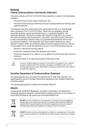
... conditions: • This device may cause harmful interference to provide reasonable protection against harmful interference in our products at ASUS REACH website at http://green.asus.com/english/REACH.htm. DO NOT throw the motherboard in municipal waste. These limits are designed to radio communications. This class B digital apparatus complies with the REACH...
... conditions: • This device may cause harmful interference to provide reasonable protection against harmful interference in our products at ASUS REACH website at http://green.asus.com/english/REACH.htm. DO NOT throw the motherboard in municipal waste. These limits are designed to radio communications. This class B digital apparatus complies with the REACH...
User Manual
Page 7
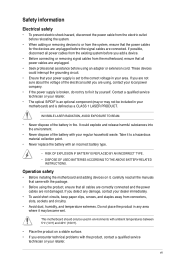
... the grounding circuit. • Ensure that your power supply is defined as a CLASS 1 LASER PRODUCT. If you encounter technical problems with your motherboard) and is set to the correct voltage in environments with ambient temperatures between 5℃ (14℉) and 40℃ (104℉). •...removing signal cables from the existing system before the signal cables are not damaged. vii If possible, disconnect all power cables from the motherboard, ensure that came with an incorrect battery type. • RISK OF EXPLOSION IF BATTERY IS REPLACED BY AN INCORRECT TYPE. •...
... the grounding circuit. • Ensure that your power supply is defined as a CLASS 1 LASER PRODUCT. If you encounter technical problems with your motherboard) and is set to the correct voltage in environments with ambient temperatures between 5℃ (14℉) and 40℃ (104℉). •...removing signal cables from the existing system before the signal cables are not damaged. vii If possible, disconnect all power cables from the motherboard, ensure that came with an incorrect battery type. • RISK OF EXPLOSION IF BATTERY IS REPLACED BY AN INCORRECT TYPE. •...
User Manual
Page 8
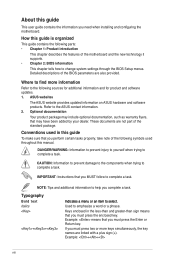
... trying to the ASUS contact information. 2. Keys enclosed in this guide To make sure that you perform certain tasks properly, take note of the following parts: • Chapter 1: Product introduction This chapter describes the features of the motherboard and the new ...65533;t. Optional documentation Your product package may include optional documentation, such as warranty flyers, that you need when installing and configuring the motherboard. Refer to complete a task. DANGER/WARNING: Information to prevent injury to yourself when trying to emphasize a word or a phrase...
... trying to the ASUS contact information. 2. Keys enclosed in this guide To make sure that you perform certain tasks properly, take note of the following parts: • Chapter 1: Product introduction This chapter describes the features of the motherboard and the new ...65533;t. Optional documentation Your product package may include optional documentation, such as warranty flyers, that you need when installing and configuring the motherboard. Refer to complete a task. DANGER/WARNING: Information to prevent injury to yourself when trying to emphasize a word or a phrase...
User Manual
Page 11
...; 2 Duo processors, which are excellent for 3D graphics and other memory-demanding applications. ASUS P5G43T-M PRO 1-1 Dual channel DDR3 1333 (O.C.)/1066/800 support This motherboard supports DDR3 memory that features data transfer rates of 1333 (O.C.)/1066/800 MHz providing great ...list below. 1.2 Package contents Check your motherboard package for the following items. Motherboard Cables Accessories Application DVD Documentation ASUS P5G43T-M PRO motherboard 2 x Serial ATA cables 1 x Ultra DMA 133/100/66 cable 1 x I/O shield ASUS motherboard support DVD User Manual If any of ...
...; 2 Duo processors, which are excellent for 3D graphics and other memory-demanding applications. ASUS P5G43T-M PRO 1-1 Dual channel DDR3 1333 (O.C.)/1066/800 support This motherboard supports DDR3 memory that features data transfer rates of 1333 (O.C.)/1066/800 MHz providing great ...list below. 1.2 Package contents Check your motherboard package for the following items. Motherboard Cables Accessories Application DVD Documentation ASUS P5G43T-M PRO motherboard 2 x Serial ATA cables 1 x Ultra DMA 133/100/66 cable 1 x I/O shield ASUS motherboard support DVD User Manual If any of ...
User Manual
Page 12
... bandwidth for advanced operating systems. 1.3.2 Innovative ASUS features ASUS MyLogo2™ This feature allows you to convert your screen. Serial ATA 3Gb/s technology This motherboard supports hard drives based on your favorite photo into the motherboard. It allows digital audio transfer and keeps ...the best signal quality. ASUS Express Gate Express Gate is a highly integrated Gb LAN ...
... bandwidth for advanced operating systems. 1.3.2 Innovative ASUS features ASUS MyLogo2™ This feature allows you to convert your screen. Serial ATA 3Gb/s technology This motherboard supports hard drives based on your favorite photo into the motherboard. It allows digital audio transfer and keeps ...the best signal quality. ASUS Express Gate Express Gate is a highly integrated Gb LAN ...
User Manual
Page 13
...-Surge Protection This special design prevents expensive devices and the motherboard from damage caused by power surges from SATA HDDs, ODDs, and USB drives. eliminates the need to http://support.asus.com for Express Gate source codes. ASUS P5G43T-M PRO 1-3 After you to turn the PC power button into an overclocking button. C.P.R. (CPU Parameter Recall...
...-Surge Protection This special design prevents expensive devices and the motherboard from damage caused by power surges from SATA HDDs, ODDs, and USB drives. eliminates the need to http://support.asus.com for Express Gate source codes. ASUS P5G43T-M PRO 1-3 After you to turn the PC power button into an overclocking button. C.P.R. (CPU Parameter Recall...
User Manual
Page 14
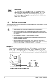
..., place it on a grounded antistatic pad or in line with the ASUS vision of creating environment-friendly and recyclable products/packaging to the motherboard, peripherals, or components. SB_PWR P5G43T-M PRO ON OFF Standby Power Powered Off P5G43T-M PRO Onboard LED 1-4 Chapter 1: Product introduction Green ASUS This motherboard and its packaging comply with the component. • Before you install...
..., place it on a grounded antistatic pad or in line with the ASUS vision of creating environment-friendly and recyclable products/packaging to the motherboard, peripherals, or components. SB_PWR P5G43T-M PRO ON OFF Standby Power Powered Off P5G43T-M PRO Onboard LED 1-4 Chapter 1: Product introduction Green ASUS This motherboard and its packaging comply with the component. • Before you install...
User Manual
Page 15
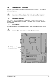
... indicated by circles to secure the motherboard to do so can damage the motherboard. Place this side towards the rear of the chassis as indicated in the correct orientation. The edge with external ports goes to the rear part of the chassis P5G43T-M PRO ASUS P5G43T-M PRO 1-5 Do not overtighten the screws! 1.5 Motherboard overview Before you unplug the...
... indicated by circles to secure the motherboard to do so can damage the motherboard. Place this side towards the rear of the chassis as indicated in the correct orientation. The edge with external ports goes to the rear part of the chassis P5G43T-M PRO ASUS P5G43T-M PRO 1-5 Do not overtighten the screws! 1.5 Motherboard overview Before you unplug the...
User Manual
Page 17
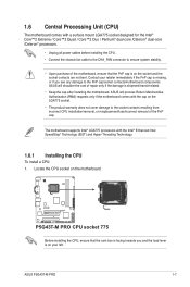
...) and Hyper-Threading Technology. 1.6.1 Installing the CPU To install a CPU: 1. ASUS will shoulder the cost of repair only if the damage is on the motherboard. 1.6 Central Processing Unit (CPU) The motherboard comes with a surface mount LGA775 socket designed for the Intel® Core™...The product warranty does not cover damage to ensure system stability. • Upon purchase of the motherboard, ensure that the cam box is on your left. ASUS P5G43T-M PRO 1-7 P5G43T-M PRO P5G43T-M PRO CPU socket 775 Before installing the CPU, ensure that the PnP cap is shipment/transit-related. ...
...) and Hyper-Threading Technology. 1.6.1 Installing the CPU To install a CPU: 1. ASUS will shoulder the cost of repair only if the damage is on the motherboard. 1.6 Central Processing Unit (CPU) The motherboard comes with a surface mount LGA775 socket designed for the Intel® Core™...The product warranty does not cover damage to ensure system stability. • Upon purchase of the motherboard, ensure that the cam box is on your left. ASUS P5G43T-M PRO 1-7 P5G43T-M PRO P5G43T-M PRO CPU socket 775 Before installing the CPU, ensure that the PnP cap is shipment/transit-related. ...

User Manual
Page 20
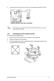
... that the CPU fan cable is for reference only. 1-10 Chapter 1: Product introduction Orient the heatsink and fan assembly such that you have installed the motherboard to the CPU heatsink or CPU before you buy a CPU separately, ensure that the four fasteners match the holes on the... motherboard. Place the heatsink on top of CPU heatsink and fan assembly may differ, but the installation steps and functions should remain the same. 1.6.2 Installing the ...
... that the CPU fan cable is for reference only. 1-10 Chapter 1: Product introduction Orient the heatsink and fan assembly such that you have installed the motherboard to the CPU heatsink or CPU before you buy a CPU separately, ensure that the four fasteners match the holes on the... motherboard. Place the heatsink on top of CPU heatsink and fan assembly may differ, but the installation steps and functions should remain the same. 1.6.2 Installing the ...
User Manual
Page 21
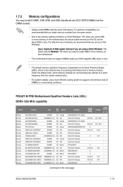
... connect the CPU fan connector! A B A B B A B A ASUS P5G43T-M PRO 1-11 3. Disconnect the CPU fan cable from the motherboard. Pull up two fasteners at a time in a diagonal sequence to the connector on the motherboard. 2. Connect the CPU fan cable to disengage the heatsink and fan assembly ...from the connector on the motherboard labeled CPU_FAN. Rotate each fastener counterclockwise. 3. CPU_FAN GND CPU FAN PWR CPU FAN IN CPU FAN PWM P5G43T-M PRO P5G43T-M PRO CPU fan connector Do not forget to plug this connector. 1.6.3 ...
... connect the CPU fan connector! A B A B B A B A ASUS P5G43T-M PRO 1-11 3. Disconnect the CPU fan cable from the motherboard. Pull up two fasteners at a time in a diagonal sequence to the connector on the motherboard. 2. Connect the CPU fan cable to disengage the heatsink and fan assembly ...from the connector on the motherboard labeled CPU_FAN. Rotate each fastener counterclockwise. 3. CPU_FAN GND CPU FAN PWR CPU FAN IN CPU FAN PWM P5G43T-M PRO P5G43T-M PRO CPU fan connector Do not forget to plug this connector. 1.6.3 ...

User Manual
Page 22
Rotate each fastener clockwise to ensure correct orientation when reinstalling. 1.7 System memory 1.7.1 Overview The motherboard comes with two Double Data Rate 3 (DDR3) Dual Inline Memory Modules (DIMM) sockets. 4. Carefully remove the heatsink and fan assembly from the motherboard. 5. The figure illustrates the location of the DDR3 DIMM sockets: DIMM_A1 DIMM_B1 Channel Channel A Channel B Sockets DIMM_A1 DIMM_B1 P5G43T-M PRO P5G43T-M PRO 240-pin DDR3 DIMM sockets 1-12 Chapter 1: Product introduction
Rotate each fastener clockwise to ensure correct orientation when reinstalling. 1.7 System memory 1.7.1 Overview The motherboard comes with two Double Data Rate 3 (DDR3) Dual Inline Memory Modules (DIMM) sockets. 4. Carefully remove the heatsink and fan assembly from the motherboard. 5. The figure illustrates the location of the DDR3 DIMM sockets: DIMM_A1 DIMM_B1 Channel Channel A Channel B Sockets DIMM_A1 DIMM_B1 P5G43T-M PRO P5G43T-M PRO 240-pin DDR3 DIMM sockets 1-12 Chapter 1: Product introduction
User Manual
Page 23
P5G43T-M PRO Motherboard Qualified Vendors Lists (QVL) DDR3-1333 MHz...ASUS P5G43T-M PRO 1-13 Install a 64-bit �W�i�nd�o�w��s® OS when you want to the memory address limitation on 32-bit Windows® OS, when you install 4GB or more memory on the motherboard. • This motherboard...; •• •• 1.8V •• 1.8V •• •• (continued on the motherboard, the actual usable memory for overclocking may install 512MB, 1GB, 2GB, and 4GB unbuffered non‑ECC DDR3 DIMMs into the...
P5G43T-M PRO Motherboard Qualified Vendors Lists (QVL) DDR3-1333 MHz...ASUS P5G43T-M PRO 1-13 Install a 64-bit �W�i�nd�o�w��s® OS when you want to the memory address limitation on 32-bit Windows® OS, when you install 4GB or more memory on the motherboard. • This motherboard...; •• •• 1.8V •• 1.8V •• •• (continued on the motherboard, the actual usable memory for overclocking may install 512MB, 1GB, 2GB, and 4GB unbuffered non‑ECC DDR3 DIMMs into the...
User Manual
Page 27
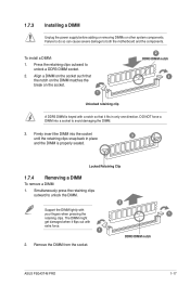
... retaining clips. Simultaneously press the retaining clips outward to both the motherboard and the components. The DIMM might get damaged when it fits in place 3 and the DIMM is properly seated. Remove the DIMM from the socket. 2 1 DDR3 DIMM notch ASUS P5G43T-M PRO 1-17 Failure to do so can cause severe damage to unlock...
... retaining clips. Simultaneously press the retaining clips outward to both the motherboard and the components. The DIMM might get damaged when it fits in place 3 and the DIMM is properly seated. Remove the DIMM from the socket. 2 1 DDR3 DIMM notch ASUS P5G43T-M PRO 1-17 Failure to do so can cause severe damage to unlock...
User Manual
Page 28
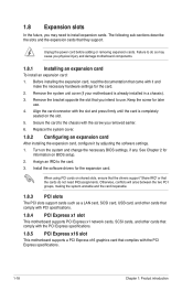
...such as a LAN card, SCSI card, USB card, and other cards that comply with PCI specifications. 1.8.4 PCI Express x1 slot This motherboard supports PCI Express x1 network cards, SCSI cards, and other cards that comply with the PCI Express specifications. 1.8.5 PCI Express x16 slot This... it and make the necessary hardware settings for later use . 1.8 Expansion slots In the future, you may cause you physical injury and damage motherboard components. 1.8.1 Installing an expansion card To install an expansion card: 1. Assign an IRQ to do not need to install expansion cards. Install the...
...such as a LAN card, SCSI card, USB card, and other cards that comply with PCI specifications. 1.8.4 PCI Express x1 slot This motherboard supports PCI Express x1 network cards, SCSI cards, and other cards that comply with the PCI Express specifications. 1.8.5 PCI Express x16 slot This... it and make the necessary hardware settings for later use . 1.8 Expansion slots In the future, you may cause you physical injury and damage motherboard components. 1.8.1 Installing an expansion card To install an expansion card: 1. Assign an IRQ to do not need to install expansion cards. Install the...
User Manual
Page 31
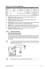
...protected content. 15. CHA_FAN CPU_FAN GND CPU FAN PWR CPU FAN IN CPU FAN PWM Rotation +12V GND P5G43T-M PRO P5G43T-M PRO fan connectors Only the 4-pin CPU fan connector supports the ASUS Q-FAN feature. ASUS P5G43T-M PRO 1-21 USB 2.0 ports 1 and 2. DVI-D Out port. Connect the fan cables to the fan connectors...compatible device and is for connecting USB 2.0 devices. 12. Insufficient air flow inside the system may damage the motherboard components. Do not place jumper caps on the motherboard, ensuring that the black wire of each cable matches the ground pin of HD DVD, Blu-Rau, and ...
...protected content. 15. CHA_FAN CPU_FAN GND CPU FAN PWR CPU FAN IN CPU FAN PWM Rotation +12V GND P5G43T-M PRO P5G43T-M PRO fan connectors Only the 4-pin CPU fan connector supports the ASUS Q-FAN feature. ASUS P5G43T-M PRO 1-21 USB 2.0 ports 1 and 2. DVI-D Out port. Connect the fan cables to the fan connectors...compatible device and is for connecting USB 2.0 devices. 12. Insufficient air flow inside the system may damage the motherboard components. Do not place jumper caps on the motherboard, ensuring that the black wire of each cable matches the ground pin of HD DVD, Blu-Rau, and ...
User Manual
Page 34
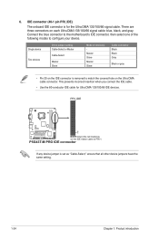
There are three connectors on the IDE ribbon cable to the motherboard's IDE connector, then select one of device(s) Master Slave Master Slave Cable connector Black Black Gray Black or gray • Pin 20 on the IDE ... setting. 1-24 Chapter 1: Product introduction 6. IDE connector (40-1 pin PRI_IDE) The onboard IDE connector is for Ultra DMA 133/100/66 IDE devices. PRI_IDE PIN1 P5G43T-M PRO NOTE:Orient the red markings on each Ultra DMA 133/100/66 signal cable: blue, black, and gray. Connect the blue connector to PIN 1. Single...
There are three connectors on the IDE ribbon cable to the motherboard's IDE connector, then select one of device(s) Master Slave Master Slave Cable connector Black Black Gray Black or gray • Pin 20 on the IDE ... setting. 1-24 Chapter 1: Product introduction 6. IDE connector (40-1 pin PRI_IDE) The onboard IDE connector is for Ultra DMA 133/100/66 IDE devices. PRI_IDE PIN1 P5G43T-M PRO NOTE:Orient the red markings on each Ultra DMA 133/100/66 signal cable: blue, black, and gray. Connect the blue connector to PIN 1. Single...
User Manual
Page 36
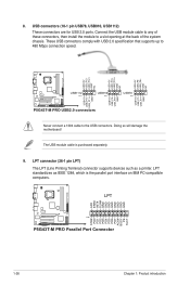
... SLIN# GND GND GND GND GND GND GND GND STB# PD0 PD1 PD2 PD3 PD4 PD5 PD6 PD7 ACK# BUSY PE SLCT P5G43T-M PRO PIN 1 P5G43T-M PRO Parallel Port Connector 1-26 Chapter 1: Product introduction USB connectors (10-1 pin USB78, USB910, USB1112) These connectors are for USB ... purchased separately. 9. 8. Doing so will damage the motherboard! USB+5V USB_P8USB_P8+ GND NC USB+5V USB_P10USB_P10+ GND NC USB+5V USB_P12USB_P12+ GND NC USB+5V USB_P7USB_P7+ GND P5G43T-M PRO USB1112 PIN 1 USB910 PIN 1 USB+5V USB_P11USB_P11+ GND P5G43T-M PRO USB2.0 connectors USB+5V USB_P9USB_P9+ GND USB78 PIN ...
... SLIN# GND GND GND GND GND GND GND GND STB# PD0 PD1 PD2 PD3 PD4 PD5 PD6 PD7 ACK# BUSY PE SLCT P5G43T-M PRO PIN 1 P5G43T-M PRO Parallel Port Connector 1-26 Chapter 1: Product introduction USB connectors (10-1 pin USB78, USB910, USB1112) These connectors are for USB ... purchased separately. 9. 8. Doing so will damage the motherboard! USB+5V USB_P8USB_P8+ GND NC USB+5V USB_P10USB_P10+ GND NC USB+5V USB_P12USB_P12+ GND NC USB+5V USB_P7USB_P7+ GND P5G43T-M PRO USB1112 PIN 1 USB910 PIN 1 USB+5V USB_P11USB_P11+ GND P5G43T-M PRO USB2.0 connectors USB+5V USB_P9USB_P9+ GND USB78 PIN ...


