User Manual
Page 4
... Jumper Settings 13 Compatible Cyrix CPU Identification 15 2. External Connectors 22 Power Connection Procedures 31 IV. INTRODUCTION 7 How this manual is organized 7 Item Checklist 7 II. CONTENTS I. FEATURES 8 Features of the ASUS HX97 Motherboard 8 Parts of PNP and PCI Setup 48 Load BIOS Defaults 50 Load Setup Defaults 50 Supervisor Password and User Password 51 IDE HDD Auto Detection 52 Save and Exit Setup 53 Exit Without Saving 53 4 ASUS HX97 User's Manual BIOS Setup 35 Load Defaults 36 Standard CMOS Setup 36 Details of Standard CMOS Setup...
... Jumper Settings 13 Compatible Cyrix CPU Identification 15 2. External Connectors 22 Power Connection Procedures 31 IV. INTRODUCTION 7 How this manual is organized 7 Item Checklist 7 II. CONTENTS I. FEATURES 8 Features of the ASUS HX97 Motherboard 8 Parts of PNP and PCI Setup 48 Load BIOS Defaults 50 Load Setup Defaults 50 Supervisor Password and User Password 51 IDE HDD Auto Detection 52 Save and Exit Setup 53 Exit Without Saving 53 4 ASUS HX97 User's Manual BIOS Setup 35 Load Defaults 36 Standard CMOS Setup 36 Details of Standard CMOS Setup...
User Manual
Page 7
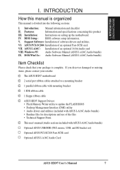
... Checklist Please check that your retailer. √ The ASUS HX97 motherboard √ 2 serial port ribbon cables attached to a mounting bracket √ 1 parallel ribbon cable with mounting bracket √ 1 IDE ribbon cable √ 1 floppy ribbon cable √ ASUS HX97 Support Drivers: • Flash Memory Writer utility to update the FLASH BIOS • Desktop Management Interface (DMI) utility • Audio drivers and utilities (included with ASUS I-A16C Audio bundle) • Readme files for descriptions and use of an optional 16-bit Audio card VIII.
... Checklist Please check that your retailer. √ The ASUS HX97 motherboard √ 2 serial port ribbon cables attached to a mounting bracket √ 1 parallel ribbon cable with mounting bracket √ 1 IDE ribbon cable √ 1 floppy ribbon cable √ ASUS HX97 Support Drivers: • Flash Memory Writer utility to update the FLASH BIOS • Desktop Management Interface (DMI) utility • Audio drivers and utilities (included with ASUS I-A16C Audio bundle) • Readme files for descriptions and use of an optional 16-bit Audio card VIII.
User Manual
Page 8
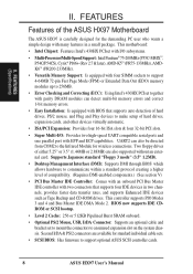
... card. BIOS now supports IDE CDROM or SCSI bootup. • Level 2 Cache: 256 or 512KB Pipelined Burst SRAM onboard. • Optional PS/2 Mouse, USB, IrDA Connector: Supports an optional cable and bracket set to mount the connectors to make setup of hard drives, PS/2 mouse, and Plug and Play devices to an unused expansion slot on the system chassis. This motherboard: • Intel Chipset: Features Intel's 430HX PCIset with I /O: Provides two high-speed UART compatible serial ports...
... card. BIOS now supports IDE CDROM or SCSI bootup. • Level 2 Cache: 256 or 512KB Pipelined Burst SRAM onboard. • Optional PS/2 Mouse, USB, IrDA Connector: Supports an optional cable and bracket set to mount the connectors to make setup of hard drives, PS/2 mouse, and Plug and Play devices to an unused expansion slot on the system chassis. This motherboard: • Intel Chipset: Features Intel's 430HX PCIset with I /O: Provides two high-speed UART compatible serial ports...

User Manual
Page 10
... Connectors CPU Voltage Switching Voltage Regulators 10 III. INSTALLATION (Map of the ASUS HX97 Motherboard SIMM Socket 4 (32-bit, 72-pin module) SIMM Socket 3 (32-bit, 72-pin module) SIMM Socket 2 (32-bit, 72-pin module) SIMM Socket 1 (32-bit, 72-pin module) Secondary IDE P8 P9 Floppy Drives Primary IDE PCI Slot 1 COM 1 COM 2 Super Multi-I/O PCI Slot 2 PCI Slot 3 PS/2 Mouse, USB, IrDA PCI Slot 4 ISA Slot 1 Keyboard BIOS ISA Slot 2 ISA Slot 3 R ISA Slot 4 Intel PIIX3 PCIset Boot Block Write Battery Test CR2032 3Volts Lithium Cell (BIOS Power) CPU ZIF Socket 7 CPU Fan...
... Connectors CPU Voltage Switching Voltage Regulators 10 III. INSTALLATION (Map of the ASUS HX97 Motherboard SIMM Socket 4 (32-bit, 72-pin module) SIMM Socket 3 (32-bit, 72-pin module) SIMM Socket 2 (32-bit, 72-pin module) SIMM Socket 1 (32-bit, 72-pin module) Secondary IDE P8 P9 Floppy Drives Primary IDE PCI Slot 1 COM 1 COM 2 Super Multi-I/O PCI Slot 2 PCI Slot 3 PS/2 Mouse, USB, IrDA PCI Slot 4 ISA Slot 1 Keyboard BIOS ISA Slot 2 ISA Slot 3 R ISA Slot 4 Intel PIIX3 PCIset Boot Block Write Battery Test CR2032 3Volts Lithium Cell (BIOS Power) CPU ZIF Socket 7 CPU Fan...

User Manual
Page 11
...Socket 7 4) PCI Slots 5) ISA Slots p. 17 System Memory Upgrade p. 18 72-Pin SIMM Memory Expansion Sockets p. 19 Central Processing Unit (CPU) Socket p. 20 32-bit PCI Bus Expansion Slots p. 20 16-bit ISA Bus Expansion Slots Connectors 1) KBCON 2) FLOPPY 3) PRINTER 4) COM1, COM2 5) Primary / Second IDE 6) IDE (HD) LED 7) PS2MOUSE/USB/IR 8) IR 9) PS2MOUSE 10) TB LED (PANEL) 11) SMI (PANEL) 12) RESET (PANEL) 13) KEYLOCK (PANEL) 14) SPEAKER (PANEL) 15) FAN 16) POWER p. 22 Keyboard Connector (5-pin Female) p. 22 Floppy Drive Connector (34-pin Block) p. 23 Parallel (Printer) Port Connector (26-pin...
...Socket 7 4) PCI Slots 5) ISA Slots p. 17 System Memory Upgrade p. 18 72-Pin SIMM Memory Expansion Sockets p. 19 Central Processing Unit (CPU) Socket p. 20 32-bit PCI Bus Expansion Slots p. 20 16-bit ISA Bus Expansion Slots Connectors 1) KBCON 2) FLOPPY 3) PRINTER 4) COM1, COM2 5) Primary / Second IDE 6) IDE (HD) LED 7) PS2MOUSE/USB/IR 8) IR 9) PS2MOUSE 10) TB LED (PANEL) 11) SMI (PANEL) 12) RESET (PANEL) 13) KEYLOCK (PANEL) 14) SPEAKER (PANEL) 15) FAN 16) POWER p. 22 Keyboard Connector (5-pin Female) p. 22 Floppy Drive Connector (34-pin Block) p. 23 Parallel (Printer) Port Connector (26-pin...

User Manual
Page 12
... made through the use of the Motherboard" on the board. Use the diagrams in this manual instead of jumpers. The jumper settings will be shown as to connect pins 1&2 and to connect pins 2&3. Connect Ribbon Cables, Cabinet Wires, and Power Supply 6. To connect the pins, simply place a plastic jumper cap over the two pins as [----], [1-2], [2-3] for our motherboards is written besides pin 1 on jumpers with two jumper numbers require that came with the keyboard connector away from static...
... made through the use of the Motherboard" on the board. Use the diagrams in this manual instead of jumpers. The jumper settings will be shown as to connect pins 1&2 and to connect pins 2&3. Connect Ribbon Cables, Cabinet Wires, and Power Supply 6. To connect the pins, simply place a plastic jumper cap over the two pins as [----], [1-2], [2-3] for our motherboards is written besides pin 1 on jumpers with two jumper numbers require that came with the keyboard connector away from static...

User Manual
Page 14
INSTALLATION (Jumpers) 14 ASUS HX97 User's Manual INSTALLATION 2. Battery Test Jumper (For Service Use Only) You can test the battery's current by this action. WARNING: You must unplug the power cord to your power supply to ensure that there is not a jumper) RTC RAM Clear R III. To clear the RTC data: (1) Turn off your computer, (2) Short the two pads (Labeled: SHORT HERE TO CLEAR CMOS) momentarily with a metallic object (3) Turn on your motherboard. RTC RAM Operation Clear Data...
INSTALLATION (Jumpers) 14 ASUS HX97 User's Manual INSTALLATION 2. Battery Test Jumper (For Service Use Only) You can test the battery's current by this action. WARNING: You must unplug the power cord to your power supply to ensure that there is not a jumper) RTC RAM Clear R III. To clear the RTC data: (1) Turn off your computer, (2) Short the two pads (Labeled: SHORT HERE TO CLEAR CMOS) momentarily with a metallic object (3) Turn on your motherboard. RTC RAM Operation Clear Data...
User Manual
Page 21
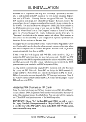
... two devices are handled the same way as the IRQ assignment process described above. If the system has both Legacy and PNP may occur. ASUS HX97 User's Manual 21 IMPORTANT: Choose "Yes" for this motherboard use IRQs. INSTALLATION (DMA Channels) III. For Windows 95 users, the "Control Panel" icon in "IRQ xx Used By ISA" and "DMA x Used By ISA" of the BIOS Setup utility. For PNP cards, IRQs...
... two devices are handled the same way as the IRQ assignment process described above. If the system has both Legacy and PNP may occur. ASUS HX97 User's Manual 21 IMPORTANT: Choose "Yes" for this motherboard use IRQs. INSTALLATION (DMA Channels) III. For Windows 95 users, the "Control Panel" icon in "IRQ xx Used By ISA" and "DMA x Used By ISA" of the BIOS Setup utility. For PNP cards, IRQs...

User Manual
Page 27
... the BIOS but the keyboard will not cause any problems. May require one or two pushes depending on the default setting of rebooting in sleep mode. 14. Speaker Connector (SPEAKER) This 4-pin connector connects to the case-mounted suspend switch. INSTALLATION (Connectors) III. INSTALLATION 10. R Turbo or Power LED +5V GND SMI Lead GND Reset SW GND System Panel Connectors +5V NC Power LED & GND LOCK Keyboard Lock GND +5V GND Speaker GND Connector SPKR ASUS HX97 User's Manual 27 This 2-pin connector...
... the BIOS but the keyboard will not cause any problems. May require one or two pushes depending on the default setting of rebooting in sleep mode. 14. Speaker Connector (SPEAKER) This 4-pin connector connects to the case-mounted suspend switch. INSTALLATION (Connectors) III. INSTALLATION 10. R Turbo or Power LED +5V GND SMI Lead GND Reset SW GND System Panel Connectors +5V NC Power LED & GND LOCK Keyboard Lock GND +5V GND Speaker GND Connector SPKR ASUS HX97 User's Manual 27 This 2-pin connector...

User Manual
Page 31
... your system user's manual. 4. The power LED on the chain) c. For ATX power supplies, you turn off position as instructed by . 3. INSTALLATION Power Connection Procedures 1. Make sure that is pressed. Your system power. For ATX power supplies, you can select shut down the computer from the time you can press the ATX power switch after windows shut down with the last device on the front panel of the case. 6. Recheck your jumper settings and connections or...
... your system user's manual. 4. The power LED on the chain) c. For ATX power supplies, you turn off position as instructed by . 3. INSTALLATION Power Connection Procedures 1. Make sure that is pressed. Your system power. For ATX power supplies, you can select shut down the computer from the time you can press the ATX power switch after windows shut down with the last device on the front panel of the case. 6. Recheck your jumper settings and connections or...
User Manual
Page 32
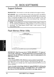
... Inc. Flash Type -- If "unknown" is shown after "Flash type --," then this ROM chip is the Flash Memory Writer utility that updates the BIOS by uploading a new BIOS file to the programmable flash ROM chip on the upper left-hand corner of the Flash memory chip onto a diskette. Save Current BIOS to reinstall it. To determine the BIOS version, check the last four numbers of the code displayed on the motherboard. SST 29EE010 Current BIOS Revision...
... Inc. Flash Type -- If "unknown" is shown after "Flash type --," then this ROM chip is the Flash Memory Writer utility that updates the BIOS by uploading a new BIOS file to the programmable flash ROM chip on the upper left-hand corner of the Flash memory chip onto a diskette. Save Current BIOS to reinstall it. To determine the BIOS version, check the last four numbers of the code displayed on the motherboard. SST 29EE010 Current BIOS Revision...
User Manual
Page 34
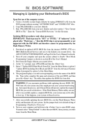
... disk. IV. Copy PFLASH.EXE to its default setting of the User's Manual for the file name. Enter the "Current BIOS Revision:" for details. 2. See ASUS CONTACT INFORMATION on your computer and open the system cabinet to enter BIOS setup. The program displays a second screen prompting you encounter problems while updating the new BIOS, DO NOT turn off your new diskette. 3. IV. Enter 2 "Update BIOS Main Block From File" from the Main Menu or option 2 "Update BIOS Including Boot...
... disk. IV. Copy PFLASH.EXE to its default setting of the User's Manual for the file name. Enter the "Current BIOS Revision:" for details. 2. See ASUS CONTACT INFORMATION on your computer and open the system cabinet to enter BIOS setup. The program displays a second screen prompting you encounter problems while updating the new BIOS, DO NOT turn off your new diskette. 3. IV. Enter 2 "Update BIOS Main Block From File" from the Main Menu or option 2 "Update BIOS Including Boot...
User Manual
Page 35
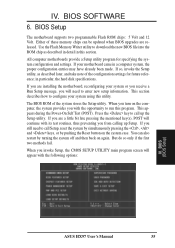
Use the Flash Memory Writer utility to run this program. If your motherboard came in particular, the hard disk specifications. BIOS (BIOS Setup) ASUS HX97 User's Manual 35 If so, invoke the Setup utility, as described in detail in this utility. When you with the opportunity to download the new BIOS file into the ROM chip as described later, and take note of the configuration settings for specifying the system configuration and settings. Press the key to enter new...
Use the Flash Memory Writer utility to run this program. If your motherboard came in particular, the hard disk specifications. BIOS (BIOS Setup) ASUS HX97 User's Manual 35 If so, invoke the Setup utility, as described in detail in this utility. When you with the opportunity to download the new BIOS file into the ROM chip as described later, and take note of the configuration settings for specifying the system configuration and settings. Press the key to enter new...

User Manual
Page 36
... onboard CMOS battery weakens. IV. "Load Setup Defaults", on the board gets lost or corrupted when the power of these keys and their respective uses. However, if the configuration stored in the CMOS memory on the other hand, is already installed in a working system, you need to provide you with the information you need . If the motherboard is for loading optimized defaults for troubleshooting. BIOS SOFTWARE Load Defaults The "Load BIOS Defaults" option loads the minimized settings for regular use...
... onboard CMOS battery weakens. IV. "Load Setup Defaults", on the board gets lost or corrupted when the power of these keys and their respective uses. However, if the configuration stored in the CMOS memory on the other hand, is already installed in a working system, you need to provide you with the information you need . If the motherboard is for loading optimized defaults for troubleshooting. BIOS SOFTWARE Load Defaults The "Load BIOS Defaults" option loads the minimized settings for regular use...
User Manual
Page 40
... multiple operating systems to check first the hard disk and then the floppy drive; Most IDE drives, except older versions, can specify a password by allowing the setting of files from the computer system to be used on bootup. The other option is Setup, where the system always boots up . BIOS SOFTWARE Quick Power On Self Test (Enabled) This field speeds up . Options are HDD MAX, Disabled 2, 4, 8, 16, and 32. A,C; that is called up...
... multiple operating systems to check first the hard disk and then the floppy drive; Most IDE drives, except older versions, can specify a password by allowing the setting of files from the computer system to be used on bootup. The other option is Setup, where the system always boots up . BIOS SOFTWARE Quick Power On Self Test (Enabled) This field speeds up . Options are HDD MAX, Disabled 2, 4, 8, 16, and 32. A,C; that is called up...

User Manual
Page 47
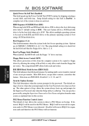
... case. This connector connects to include in the given order) after which is Enabled. HDD Power Down shuts down any software alarm clock or event calendar can enable power management for this software cannot display. at the right of inactivity. You can wake up call of time after one hour. IRQ8 (Real Time Alarm) is user-configurable to control the video display card if it supports the DPMS feature; IV. BIOS (Power...
... case. This connector connects to include in the given order) after which is Enabled. HDD Power Down shuts down any software alarm clock or event calendar can enable power management for this software cannot display. at the right of inactivity. You can wake up call of time after one hour. IRQ8 (Real Time Alarm) is user-configurable to control the video display card if it supports the DPMS feature; IV. BIOS (Power...

User Manual
Page 48
... and PCI Setup" option configures the PCI bus slots. Slot 1/2/3/4 IRQ (Auto) The first four fields on the system use . BIOS (PnP and PCI) NOTE: SETUP Defaults are noted in parenthesis next to determine IRQ use INTA#, thus all installed PCI cards must be reassigned by the OS when Yes is selected. Slot 1 (Right) is installed or to this motherboard. 48 ASUS HX97 User's Manual When a non-Plug and Play OS is nearest the memory sockets. PCI Latency...
... and PCI Setup" option configures the PCI bus slots. Slot 1/2/3/4 IRQ (Auto) The first four fields on the system use . BIOS (PnP and PCI) NOTE: SETUP Defaults are noted in parenthesis next to determine IRQ use INTA#, thus all installed PCI cards must be reassigned by the OS when Yes is selected. Slot 1 (Right) is installed or to this motherboard. 48 ASUS HX97 User's Manual When a non-Plug and Play OS is nearest the memory sockets. PCI Latency...
User Manual
Page 49
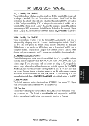
... to specify its default setting of a Legacy ISA card that the displayed DMA channel is not used or an ICU is being used by a Legacy (non-PnP) ISA card. If you are not using an ICU to Enabled. SCSI BIOS (Auto) The default uses Auto settings for selecting the block size. If you can set to Disabled until support disks and USB devices are available in your system that channel to Yes. Available options include: No/ICU...
... to specify its default setting of a Legacy ISA card that the displayed DMA channel is not used or an ICU is being used by a Legacy (non-PnP) ISA card. If you are not using an ICU to Enabled. SCSI BIOS (Auto) The default uses Auto settings for selecting the block size. If you can set to Disabled until support disks and USB devices are available in your system that channel to Yes. Available options include: No/ICU...

User Manual
Page 51
... password. After setting a password, the screen automatically reverts to type it again. A message confirms the password has been disabled. ASUS HX97 User's Manual 51 IV. BIOS SOFTWARE Supervisor Password and User Password These two options set the system passwords. To specify a password, highlight the type you want and then press the key. If you want to protect the system and the Setup utility; "Supervisor Password" sets a password that the password is case sensitive, and can be used to disable either password...
... password. After setting a password, the screen automatically reverts to type it again. A message confirms the password has been disabled. ASUS HX97 User's Manual 51 IV. BIOS SOFTWARE Supervisor Password and User Password These two options set the system passwords. To specify a password, highlight the type you want and then press the key. If you want to protect the system and the Setup utility; "Supervisor Password" sets a password that the password is case sensitive, and can be used to disable either password...
User Manual
Page 52
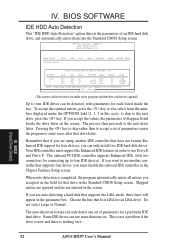
... the key or else select from inside the box. Remember that if you are using another controller that supports four drives, you must disable the onboard IDE controller in this case); Your IDE controller must use Drive E and Drive F. When auto-detection is nothing on it. Some IDE drives can only install two IDE hard disk drives. ROM PCI/ISA BIOS () CMOS SETUP UTILITY AWARD SOFTWARE, INC. Choose the line that drive letter. IV. BIOS (Hard Drive Detect) 52 ASUS HX97 User's Manual If you want to use more...
... the key or else select from inside the box. Remember that if you are using another controller that supports four drives, you must disable the onboard IDE controller in this case); Your IDE controller must use Drive E and Drive F. When auto-detection is nothing on it. Some IDE drives can only install two IDE hard disk drives. ROM PCI/ISA BIOS () CMOS SETUP UTILITY AWARD SOFTWARE, INC. Choose the line that drive letter. IV. BIOS (Hard Drive Detect) 52 ASUS HX97 User's Manual If you want to use more...


