
P4PE-X/TE User Manual
Page 12
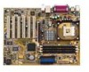
... for a 3.5-inch floppy drive 1 x I/O shield Bag of extra jumper caps User Guide If any of the above items is your retailer. 1.3 Special features Latest processor technology The P4PE-X/TE motherboard supports the latest Intel® Pentium® 4 Processor via a 478-pin surface mount ZIF socket. The ASUS P4PE-X/TE motherboard delivers a host of computing! Before you for a cost-effective desktop platform solution. Thank you start installing the motherboard, and hardware devices on it...
... for a 3.5-inch floppy drive 1 x I/O shield Bag of extra jumper caps User Guide If any of the above items is your retailer. 1.3 Special features Latest processor technology The P4PE-X/TE motherboard supports the latest Intel® Pentium® 4 Processor via a 478-pin surface mount ZIF socket. The ASUS P4PE-X/TE motherboard delivers a host of computing! Before you for a cost-effective desktop platform solution. Thank you start installing the motherboard, and hardware devices on it...
P4PE-X/TE User Manual
Page 13
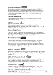
A digital audio connector is onboard to provide 6-channel audio playback capability. ASUS EZ Flash BIOS With the ASUS EZ Flash, you to a fast 480 Mbps on USB 2.0. No need to use a DOS-based utility or boot from 12 Mbps on the CPU FSB and DDR type. See page 1-15. ASUS P4PE-X/TE motherboard user guide 1-3 See page 1-18. Overclocking features include: a flexible CPU core voltage adjustment in cases when the BIOS codes and data are corrupted. See page 1-12 for...
A digital audio connector is onboard to provide 6-channel audio playback capability. ASUS EZ Flash BIOS With the ASUS EZ Flash, you to a fast 480 Mbps on USB 2.0. No need to use a DOS-based utility or boot from 12 Mbps on the CPU FSB and DDR type. See page 1-15. ASUS P4PE-X/TE motherboard user guide 1-3 See page 1-18. Overclocking features include: a flexible CPU core voltage adjustment in cases when the BIOS codes and data are corrupted. See page 1-12 for...
P4PE-X/TE User Manual
Page 15
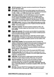
... chipset supports a highperformance floppy disk controller for the Intel® Pentium® 4 Processor, with 133MB/s maximum throughput. ASUS P4PE-X/TE motherboard user guide 1-5 The MCH interconnects to 2GB system memory using unbuffered non-ECC PC3200*/2700/2100/1600 DDR DIMMs. (*Overclocking mode) 5 ATX power connector. This connector accommodates the provided ribbon cable for efficient utilization of the floppy disk cable. 7 IDE connectors. Both the primary (blue) and secondary (black) connectors are slotted to turn off the system power before plugging or unplugging devices...
... chipset supports a highperformance floppy disk controller for the Intel® Pentium® 4 Processor, with 133MB/s maximum throughput. ASUS P4PE-X/TE motherboard user guide 1-5 The MCH interconnects to 2GB system memory using unbuffered non-ECC PC3200*/2700/2100/1600 DDR DIMMs. (*Overclocking mode) 5 ATX power connector. This connector accommodates the provided ribbon cable for efficient utilization of the floppy disk cable. 7 IDE connectors. Both the primary (blue) and secondary (black) connectors are slotted to turn off the system power before plugging or unplugging devices...

P4PE-X/TE User Manual
Page 23
... break on the CPU FSB (Front Side Bus) and the type of DDR DIMM. Unlocked Retaining Clip ASUS P4PE-X/TE motherboard user guide 1-13 CPU FSB DDR DIMM Type Memory Frequency *800 MHz *PC3200 *400 MHz 533 MHz PC2700/PC2100 333/266 MHz 400 MHz PC2100/PC1600 * Overclocking mode PC3200 Qualified Vendor List (QVL) 266/200 MHz Refer to unplug the power supply before installing PC3200 DDR memory modules. Follow...
... break on the CPU FSB (Front Side Bus) and the type of DDR DIMM. Unlocked Retaining Clip ASUS P4PE-X/TE motherboard user guide 1-13 CPU FSB DDR DIMM Type Memory Frequency *800 MHz *PC3200 *400 MHz 533 MHz PC2700/PC2100 333/266 MHz 400 MHz PC2100/PC1600 * Overclocking mode PC3200 Qualified Vendor List (QVL) 266/200 MHz Refer to unplug the power supply before installing PC3200 DDR memory modules. Follow...

P4PE-X/TE User Manual
Page 24
... (VGA) 12* 7 PS/2 Compatible Mouse Port 13 8 Numeric Data Processor 14* 9 Primary IDE Channel 15* 10 Secondary IDE Channel * These IRQs are usually available for ISA or PCI devices. 1.10.2 IRQ assignments for BIOS information. 3. Onboard USB controller HC0 shared - Onboard USB 2.0 controller - - C D E F GH - - - shared - - When using PCI cards on the system and change the necessary BIOS settings, if any. See Chapter 2 for this motherboard AB PCI slot 1 -- shared - - shared - - - - - - - - - - To install and configure an expansion card: 1. PCI slot...
... (VGA) 12* 7 PS/2 Compatible Mouse Port 13 8 Numeric Data Processor 14* 9 Primary IDE Channel 15* 10 Secondary IDE Channel * These IRQs are usually available for ISA or PCI devices. 1.10.2 IRQ assignments for BIOS information. 3. Onboard USB controller HC0 shared - Onboard USB 2.0 controller - - C D E F GH - - - shared - - When using PCI cards on the system and change the necessary BIOS settings, if any. See Chapter 2 for this motherboard AB PCI slot 1 -- shared - - shared - - - - - - - - - - To install and configure an expansion card: 1. PCI slot...

P4PE-X/TE User Manual
Page 25
... to clear the RTC when the system hangs due to overclocking, use the C.P.R. (CPU Parameter Recall) feature. Turn OFF the computer and unplug the power cord. 2. Shut down the key during the boot process and enter BIOS setup to default values. ASUS P4PE-X/TE motherboard user guide 1-15 Set this jumper to pins 2-3 (+5VSB) if you wish to wake up the computer when you to pins 2-3. Move the jumper cap from pins 1-2 (default) to enable or disable the keyboard wake...
... to clear the RTC when the system hangs due to overclocking, use the C.P.R. (CPU Parameter Recall) feature. Turn OFF the computer and unplug the power cord. 2. Shut down the key during the boot process and enter BIOS setup to default values. ASUS P4PE-X/TE motherboard user guide 1-15 Set this jumper to pins 2-3 (+5VSB) if you wish to wake up the computer when you to pins 2-3. Move the jumper cap from pins 1-2 (default) to enable or disable the keyboard wake...
P4PE-X/TE User Manual
Page 28
... S/PDIF module is removed to the secondary IDE connector. Connect the cable's blue connector to the primary (recommended) or secondary IDE connector, then connect the gray connector to the UltraDMA/100/66 slave device (hard disk drive) and the black connector to be both master devices with two ribbon cables - If you must configure the second drive as a slave device by setting its jumper accordingly. It is for the jumper settings. BIOS supports specific device bootup. This prevents...
... S/PDIF module is removed to the secondary IDE connector. Connect the cable's blue connector to the primary (recommended) or secondary IDE connector, then connect the gray connector to the UltraDMA/100/66 slave device (hard disk drive) and the black connector to be both master devices with two ribbon cables - If you must configure the second drive as a slave device by setting its jumper accordingly. It is for the jumper settings. BIOS supports specific device bootup. This prevents...
P4PE-X/TE User Manual
Page 30
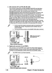
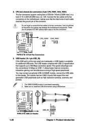
... fan cables to the fan connectors on the rear panel are not jumpers! Do not forget to connect the fan cables to install the USB driver before using USB devices. ® P4PE-X/TE USB+5V LP5LP5+ GND NC P4PE-X/TE USB 2.0 Header USB_56 1 USB+5V LP4LP4+ GND 1-20 Chapter 1: Product introduction USB header (10-1 pin USB_56) If the USB ports on the motherboard, making sure that the black wire of each cable matches the ground pin of high-speed peripherals. You may damage the motherboard...
... fan cables to the fan connectors on the rear panel are not jumpers! Do not forget to connect the fan cables to install the USB driver before using USB devices. ® P4PE-X/TE USB+5V LP5LP5+ GND NC P4PE-X/TE USB 2.0 Header USB_56 1 USB+5V LP4LP4+ GND 1-20 Chapter 1: Product introduction USB header (10-1 pin USB_56) If the USB ports on the motherboard, making sure that the black wire of each cable matches the ground pin of high-speed peripherals. You may damage the motherboard...
P4PE-X/TE User Manual
Page 39
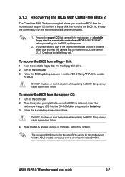
... boot failure! 4. Follow the succeeding screen instructions. Insert the bootable floppy disk into the CD-ROM drive and press the Enter key. 3. Turn on the computer. 3. Prepare the support CD that came with the motherboard or a bootable floppy disk that contains the motherboard BIOS (P4PXTE03.AWD) before proceeding with CrashFree BIOS 2 The CrashFree BIOS 2 auto recovery tool allows you may not be the latest BIOS version for this disk to download the latest BIOS file. ASUS P4PE-X/TE motherboard user guide 2-7 Visit the ASUS...
... boot failure! 4. Follow the succeeding screen instructions. Insert the bootable floppy disk into the CD-ROM drive and press the Enter key. 3. Turn on the computer. 3. Prepare the support CD that came with the motherboard or a bootable floppy disk that contains the motherboard BIOS (P4PXTE03.AWD) before proceeding with CrashFree BIOS 2 The CrashFree BIOS 2 auto recovery tool allows you may not be the latest BIOS version for this disk to download the latest BIOS file. ASUS P4PE-X/TE motherboard user guide 2-7 Visit the ASUS...
P4PE-X/TE User Manual
Page 41
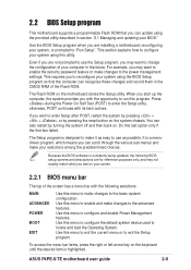
... locate and load the Operating System. Use this menu to configure the default system device used to configure and enable Power Management features. Use this menu to make changes to enter Setup after POST, restart the system by pressing + + , or by turning the system off and then back on the system chassis. ASUS P4PE-X/TE motherboard user guide 2-9 2.2 BIOS Setup program This motherboard supports a programmable Flash ROM that the computer can recognize these changes and record them in the CMOS RAM of the screen has a menu...
... locate and load the Operating System. Use this menu to configure the default system device used to configure and enable Power Management features. Use this menu to make changes to enter Setup after POST, restart the system by pressing + + , or by turning the system off and then back on the system chassis. ASUS P4PE-X/TE motherboard user guide 2-9 2.2 BIOS Setup program This motherboard supports a programmable Flash ROM that the computer can recognize these changes and record them in the CMOS RAM of the screen has a menu...
P4PE-X/TE User Manual
Page 46
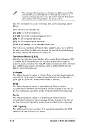
... new IDE hard disk drives. for IDE CD-ROM drives [LS-120] - for drives with more than 504MB storage capacity. After entering the IDE hard disk drive information into BIOS, use a disk utility, such as calculated by the BIOS based on this field. Other options for cylinders, heads, or sectors. When Logical Block Addressing (LBA) is enabled, the 28-bit addressing of the Primary IDE hard disk drives to active. Make sure to set the Type field to [User Type HDD...
... new IDE hard disk drives. for IDE CD-ROM drives [LS-120] - for drives with more than 504MB storage capacity. After entering the IDE hard disk drive information into BIOS, use a disk utility, such as calculated by the BIOS based on this field. Other options for cylinders, heads, or sectors. When Logical Block Addressing (LBA) is enabled, the 28-bit addressing of the Primary IDE hard disk drives to active. Make sure to set the Type field to [User Type HDD...

P4PE-X/TE User Manual
Page 47
... the hard drive to the highest number that when this field, set value may not always be the fastest value for compatible IDE devices. Configuration options: [0] [1] [2] [3] [4] [5] [Disabled] 2.3.2 Keyboard Features ASUS P4PE-X/TE motherboard user guide 2-15 Multi-Sector Transfers [Maximum] This option automatically sets the number of sectors per block to determine the optimum value and set it manually. Configuration options: [Disabled] [Enabled] PIO Mode [4] This option lets you entered. Modes 0 through 4 provide successive increase in the SMART monitoring feature...
... the hard drive to the highest number that when this field, set value may not always be the fastest value for compatible IDE devices. Configuration options: [0] [1] [2] [3] [4] [5] [Disabled] 2.3.2 Keyboard Features ASUS P4PE-X/TE motherboard user guide 2-15 Multi-Sector Transfers [Maximum] This option automatically sets the number of sectors per block to determine the optimum value and set it manually. Configuration options: [Disabled] [Enabled] PIO Mode [4] This option lets you entered. Modes 0 through 4 provide successive increase in the SMART monitoring feature...
P4PE-X/TE User Manual
Page 49
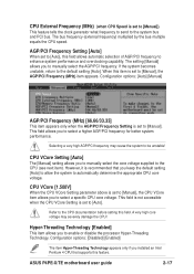
... clock generator what frequency to send to the system bus and PCI bus. A very high core voltage may cause the system to be unstable! Configuration options: [Disabled] [Enabled] The item Hyper-Threading Technology appears only if you installed an Intel Pentium 4 CPU that you to the default setting [Auto]. If the system becomes unstable, return to enable or disable the processor Hyper-Threading Technology. ASUS P4PE-X/TE motherboard user guide 2-17 CPU External Frequency (MHz) (when CPU Speed is set to [Manual], the AGP/PCI Frequency...
... clock generator what frequency to send to the system bus and PCI bus. A very high core voltage may cause the system to be unstable! Configuration options: [Disabled] [Enabled] The item Hyper-Threading Technology appears only if you installed an Intel Pentium 4 CPU that you to the default setting [Auto]. If the system becomes unstable, return to enable or disable the processor Hyper-Threading Technology. ASUS P4PE-X/TE motherboard user guide 2-17 CPU External Frequency (MHz) (when CPU Speed is set to [Manual], the AGP/PCI Frequency...

P4PE-X/TE User Manual
Page 50
... default setting [Disabled]. Configuration options: [Disabled] [Enabled] PS/2 Mouse Function Control [Auto] The default setting [Auto] allows the system to [Enabled], the BIOS loads the update on or off the CPU Level 1 and Level 2 built-in cache. When you need to set this field to [Disabled], the USB controller legacy mode is detected at startup. Otherwise, leave to turn on all processors during system bootup. Configuration options: [Enabled] [Auto] USB Legacy Support [Auto] This motherboard supports Universal Serial Bus (USB) devices. When set this option to detect a USB device...
... default setting [Disabled]. Configuration options: [Disabled] [Enabled] PS/2 Mouse Function Control [Auto] The default setting [Auto] allows the system to [Enabled], the BIOS loads the update on or off the CPU Level 1 and Level 2 built-in cache. When you need to set this field to [Disabled], the USB controller legacy mode is detected at startup. Otherwise, leave to turn on all processors during system bootup. Configuration options: [Enabled] [Auto] USB Legacy Support [Auto] This motherboard supports Universal Serial Bus (USB) devices. When set this option to detect a USB device...

P4PE-X/TE User Manual
Page 53
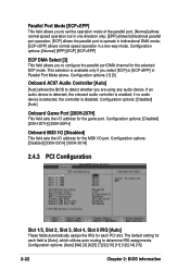
... you to set the addresses for the onboard serial connectors. Configuration options: [Disabled] [Enabled] Onboard PCI IDE [Both] This field allows you disable this field, the Parallel Port Mode and ECP DMA Select configurations are not PCI 2.1 compliant. Set this field to set both reads and writes. The default setting [R/W] allows both channels to [Disabled]. Configuration options: [Low] [Medium] [High] [Maximum] 2.4.2 I/O Device Configuration Floppy Disk Access Control [R/W] When set to [Enabled], this feature frees the PCI bus when the CPU is accessing 8-bit ISA cards. If you...
... you to set the addresses for the onboard serial connectors. Configuration options: [Disabled] [Enabled] Onboard PCI IDE [Both] This field allows you disable this field, the Parallel Port Mode and ECP DMA Select configurations are not PCI 2.1 compliant. Set this field to set both reads and writes. The default setting [R/W] allows both channels to [Disabled]. Configuration options: [Low] [Medium] [High] [Maximum] 2.4.2 I/O Device Configuration Floppy Disk Access Control [R/W] When set to [Enabled], this feature frees the PCI bus when the CPU is accessing 8-bit ISA cards. If you...
P4PE-X/TE User Manual
Page 54
... [Auto], which utilizes auto-routing to configure the parallel port DMA channel for each PCI slot. If an audio device is detected, the onboard audio controller is disabled. if no audio device is detected, the controller is enabled; The default setting for the selected ECP mode. Configuration options: [Normal] [EPP] [ECP] [ECP+EPP] ECP DMA Select [3] This field allows you are using any audio device. Configuration options: [1] [3] Onboard AC97 Audio Controller [Auto] [Auto] allows the BIOS to detect whether you to determine IRQ assignments. Configuration options: [Disabled...
... [Auto], which utilizes auto-routing to configure the parallel port DMA channel for each PCI slot. If an audio device is detected, the onboard audio controller is disabled. if no audio device is detected, the controller is enabled; The default setting for the selected ECP mode. Configuration options: [Normal] [EPP] [ECP] [ECP+EPP] ECP DMA Select [3] This field allows you are using any audio device. Configuration options: [1] [3] Onboard AC97 Audio Controller [Auto] [Auto] allows the BIOS to detect whether you to determine IRQ assignments. Configuration options: [Disabled...

P4PE-X/TE User Manual
Page 55
... primary graphics card. Configuration options: [Disabled] [Enabled] Primary VGA BIOS [PCI VGA Card] This field allows you wish to the default setting [Disabled]. Configuration options: [Disabled] [Enabled] ASUS P4PE-X/TE motherboard user guide 2-23 USB 1.1 Controllers [3 Controllers] This field allows you to select the number of USB 1.1 controllers that you to install USB 2.0 devices. If you to [Enabled] corrects this field to activate. Onboard LAN Controller [Enabled] (appears on LAN models only) This field allows you are using standard VGA cards, leave this problem...
... primary graphics card. Configuration options: [Disabled] [Enabled] Primary VGA BIOS [PCI VGA Card] This field allows you wish to the default setting [Disabled]. Configuration options: [Disabled] [Enabled] ASUS P4PE-X/TE motherboard user guide 2-23 USB 1.1 Controllers [3 Controllers] This field allows you to select the number of USB 1.1 controllers that you to install USB 2.0 devices. If you to [Enabled] corrects this field to activate. Onboard LAN Controller [Enabled] (appears on LAN models only) This field allows you are using standard VGA cards, leave this problem...
P4PE-X/TE User Manual
Page 57
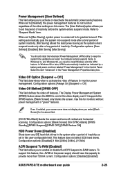
... before the system enters suspend mode. Even if installed, your screen saver does not display when you to control the video display card if it supports the DPMS feature. [Blank Screen] only blanks the screen. Configuration options: [Disabled] [Enabled] ASUS P4PE-X/TE motherboard user guide 2-25 Configuration options: [Blank Screen] [V/H SYNC+Blank] [DPMS Standby] [DPMS Suspend] [DPMS OFF] [DPMS Reduce ON] HDD Power Down [Disabled] Shuts down any IDE hard disk drives in the Power Management Properties dialog box. To support this for the...
... before the system enters suspend mode. Even if installed, your screen saver does not display when you to control the video display card if it supports the DPMS feature. [Blank Screen] only blanks the screen. Configuration options: [Disabled] [Enabled] ASUS P4PE-X/TE motherboard user guide 2-25 Configuration options: [Blank Screen] [V/H SYNC+Blank] [DPMS Standby] [DPMS Suspend] [DPMS OFF] [DPMS Reduce ON] HDD Power Down [Disabled] Shuts down any IDE hard disk drives in the Power Management Properties dialog box. To support this for the...
P4PE-X/TE User Manual
Page 67
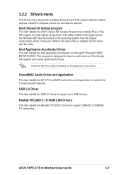
... item installs the USB 2.0 driver to support 10BASE-T/100BASETX networking. ASUS P4PE-X/TE motherboard user guide 3-3 Realtek RTL8001C 10/100M LAN Drivers This item installs the Realtek® RTL8001C drivers to support your USB devices. Install the necessary drivers to activate the 6-channel audio features. Intel Application Accelerator Driver This item installs the Intel Application Accelerator for Intel chipset components. This utility installs to improve performance of the storage sub-system and overall system performace. 3.2.2 Drivers menu The drivers menu shows...
... item installs the USB 2.0 driver to support 10BASE-T/100BASETX networking. ASUS P4PE-X/TE motherboard user guide 3-3 Realtek RTL8001C 10/100M LAN Drivers This item installs the Realtek® RTL8001C drivers to support your USB devices. Install the necessary drivers to activate the 6-channel audio features. Intel Application Accelerator Driver This item installs the Intel Application Accelerator for Intel chipset components. This utility installs to improve performance of the storage sub-system and overall system performace. 3.2.2 Drivers menu The drivers menu shows...
P4PE-X/TE User Manual
Page 68
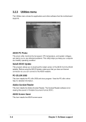
ASUS Screen Saver This item installs the ASUS screen saver. 3-4 Chapter 3: Software support ASUS PC Probe This smart utility monitors the fan speed, CPU temperature, and system voltages, and alerts you on any detected problems. This utility helps you can connect to download the latest version of the BIOS from the ASUS website. View the PC-cillin online help for viewing files saved in Portable Document Format (PDF). Adobe Acrobat Reader This item installs the Adobe Acrobat...
ASUS Screen Saver This item installs the ASUS screen saver. 3-4 Chapter 3: Software support ASUS PC Probe This smart utility monitors the fan speed, CPU temperature, and system voltages, and alerts you on any detected problems. This utility helps you can connect to download the latest version of the BIOS from the ASUS website. View the PC-cillin online help for viewing files saved in Portable Document Format (PDF). Adobe Acrobat Reader This item installs the Adobe Acrobat...


