P4PE-X/TE User Manual
Page 3
Features Contents Notices v Safety information vi About this guide vii Conventions used in this guide vii Where to find more information vii ASUS contact information viii P4PE-X/TE specifications summary ix Chapter 1: Product introduction 1-1 1.1 Welcome 1-2 1.2 Package contents 1-2 1.3 Special features 1-2 1.4 Motherboard components 1-4 1.5 ...1-14 1.11 Jumpers 1-15 1.12 Connectors 1-16 Chapter 2: BIOS information 2-1 2.1 Managing and updating your BIOS 2-2 2.1 Managing and updating your BIOS 2-2 2.1.1 Using ASUS EZ Flash to update the BIOS 2-2 2.1.2 Using AFLASH to update the...
Features Contents Notices v Safety information vi About this guide vii Conventions used in this guide vii Where to find more information vii ASUS contact information viii P4PE-X/TE specifications summary ix Chapter 1: Product introduction 1-1 1.1 Welcome 1-2 1.2 Package contents 1-2 1.3 Special features 1-2 1.4 Motherboard components 1-4 1.5 ...1-14 1.11 Jumpers 1-15 1.12 Connectors 1-16 Chapter 2: BIOS information 2-1 2.1 Managing and updating your BIOS 2-2 2.1 Managing and updating your BIOS 2-2 2.1.1 Using ASUS EZ Flash to update the BIOS 2-2 2.1.2 Using AFLASH to update the...
P4PE-X/TE User Manual
Page 4
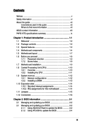
Safeguards Contents 2.1.3 Recovering the BIOS with CrashFree BIOS 2 ....... 2-7 2.1.4 BIOS beep codes 2-8 2.2 BIOS Setup program 2-9 2.2.1 BIOS menu bar 2-9 2.2.2 Legend bar 2-10 2.3 Main Menu 2-11 2.3.1 Primary and Secondary Master/Slave 2-13 2.3.2 Keyboard Features 2-15 2.4 Advanced Menu 2-16 2.4.1 Chip Configuration 2-19 2.4.2 ... Menu 2-29 2.7 Exit Menu 2-31 Chapter 3: Software support 3-1 3.1 Install an operating system 3-2 3.2 Support CD information 3-2 3.2.1 Running the support CD 3-2 3.2.2 Drivers menu 3-3 3.2.3 Utilities menu 3-4 3.2.4 ASUS Contact Information 3-5 iv
Safeguards Contents 2.1.3 Recovering the BIOS with CrashFree BIOS 2 ....... 2-7 2.1.4 BIOS beep codes 2-8 2.2 BIOS Setup program 2-9 2.2.1 BIOS menu bar 2-9 2.2.2 Legend bar 2-10 2.3 Main Menu 2-11 2.3.1 Primary and Secondary Master/Slave 2-13 2.3.2 Keyboard Features 2-15 2.4 Advanced Menu 2-16 2.4.1 Chip Configuration 2-19 2.4.2 ... Menu 2-29 2.7 Exit Menu 2-31 Chapter 3: Software support 3-1 3.1 Install an operating system 3-2 3.2 Support CD information 3-2 3.2.1 Running the support CD 3-2 3.2.2 Drivers menu 3-3 3.2.3 Utilities menu 3-4 3.2.4 ASUS Contact Information 3-5 iv
P4PE-X/TE User Manual
Page 10
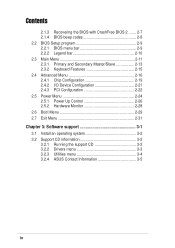
x P4PE-X/TE specifications summary BIOS features 2Mb Flash ROM, Award BIOS, TCAV, PnP, DMI2.0, SM BIOS2.3, ASUS C.P.R., ASUS EZ Flash, ASUS CrashFree BIOS2 Industry standard PCI 2.2, USB 2.0 Manageability WfM 2.0. DMI 2.0, WOL/WOR by PME, chassis intrusion, SMBus Form Factor ATX form factor: 12 in x 9.0 in (30.5 cm x 22.9 cm) Support CD contents Device drivers ASUS PC Probe ASUS LiveUpdate Trend Micro™ PC-cillin 2002 anti-virus software (OEM version) * Specifications are subject to change without notice.
x P4PE-X/TE specifications summary BIOS features 2Mb Flash ROM, Award BIOS, TCAV, PnP, DMI2.0, SM BIOS2.3, ASUS C.P.R., ASUS EZ Flash, ASUS CrashFree BIOS2 Industry standard PCI 2.2, USB 2.0 Manageability WfM 2.0. DMI 2.0, WOL/WOR by PME, chassis intrusion, SMBus Form Factor ATX form factor: 12 in x 9.0 in (30.5 cm x 22.9 cm) Support CD contents Device drivers ASUS PC Probe ASUS LiveUpdate Trend Micro™ PC-cillin 2002 anti-virus software (OEM version) * Specifications are subject to change without notice.
P4PE-X/TE User Manual
Page 13
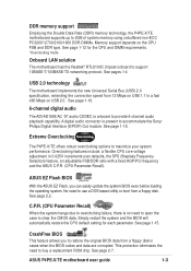
... the Double Data Rate (DDR) memory technology, the P4PE-X/TE motherboard supports up to support 10BASE-T/100BASE-TX networking protocol. Extreme Overclocking The P4PE-X/TE offers robust overclocking options to buy a replacement ROM chip. ASUS P4PE-X/TE motherboard user guide 1-3 See page 1-18. Simply restart the system and the BIOS will automatically restore the CPU default setting for...
... the Double Data Rate (DDR) memory technology, the P4PE-X/TE motherboard supports up to support 10BASE-T/100BASE-TX networking protocol. Extreme Overclocking The P4PE-X/TE offers robust overclocking options to buy a replacement ROM chip. ASUS P4PE-X/TE motherboard user guide 1-3 See page 1-18. Simply restart the system and the BIOS will automatically restore the CPU default setting for...
P4PE-X/TE User Manual
Page 15
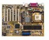
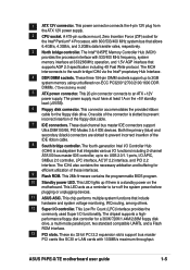
...bus master PCI cards like SCSI or LAN cards with 800/533/400 MHz system bus that supports AGP 2.0 specification including 4X Fast Write protocol. ASUS P4PE-X/TE motherboard user guide 1-5 1 ATX 12V connector. A 478-pin surface mount, Zero Insertion Force (ZIF) socket for a 360K/720K/1.44M/2.88M floppy... connects to the south bridge ICH4 via the Intel® proprietary Hub Interface. 4 DDR DIMM sockets. This 2Mb firmware contains the programmable BIOS program. 10 Standby power LED. This power connector connects the 4-pin 12V plug from the ATX 12V power supply. 2 CPU socket. ...
...bus master PCI cards like SCSI or LAN cards with 800/533/400 MHz system bus that supports AGP 2.0 specification including 4X Fast Write protocol. ASUS P4PE-X/TE motherboard user guide 1-5 1 ATX 12V connector. A 478-pin surface mount, Zero Insertion Force (ZIF) socket for a 360K/720K/1.44M/2.88M floppy... connects to the south bridge ICH4 via the Intel® proprietary Hub Interface. 4 DDR DIMM sockets. This 2Mb firmware contains the programmable BIOS program. 10 Standby power LED. This power connector connects the 4-pin 12V plug from the ATX 12V power supply. 2 CPU socket. ...
P4PE-X/TE User Manual
Page 20
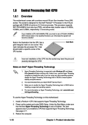
... a CPU that supports Hyper-Threading Technology. 2. To use the Hyper-Threading compliler to use a PC3200 (400MHz) DDR module listed in BIOS before installing a supported operating system. 4. The item appears only if you install WinXP Service Pack 1. 3. This processor supports 800*/533/...) 1.8.1 Overview The motherboard comes with a surface mount 478-pin Zero Insertion Force (ZIF) socket. Power up the system and enter BIOS Setup. Reboot the computer. 1-10 Chapter 1: Product introduction Hyper-Threading Technology is recommended that should match a specific corner of the CPU...
... a CPU that supports Hyper-Threading Technology. 2. To use the Hyper-Threading compliler to use a PC3200 (400MHz) DDR module listed in BIOS before installing a supported operating system. 4. The item appears only if you install WinXP Service Pack 1. 3. This processor supports 800*/533/...) 1.8.1 Overview The motherboard comes with a surface mount 478-pin Zero Insertion Force (ZIF) socket. Power up the system and enter BIOS Setup. Reboot the computer. 1-10 Chapter 1: Product introduction Hyper-Threading Technology is recommended that should match a specific corner of the CPU...

P4PE-X/TE User Manual
Page 24
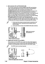
... Data Processor 14* 9 Primary IDE Channel 15* 10 Secondary IDE Channel * These IRQs are usually available for ISA or PCI devices. 1.10.2 IRQ assignments for BIOS information. 3. PCI slot 6 -- Onboard USB controller HC0 shared - C D E F GH - - - shared - - - - - - shared - - shared - - See ...and configure an expansion card: 1. PCI slot 3 -- used - - - - When using PCI cards on the system and change the necessary BIOS settings, if any. 1.10 Expansion slots The motherboard has six PCI slots and one Accelerated Graphics Port (AGP) slot. NOTE: The AGP slot...
... Data Processor 14* 9 Primary IDE Channel 15* 10 Secondary IDE Channel * These IRQs are usually available for ISA or PCI devices. 1.10.2 IRQ assignments for BIOS information. 3. PCI slot 6 -- Onboard USB controller HC0 shared - C D E F GH - - - shared - - - - - - shared - - shared - - See ...and configure an expansion card: 1. PCI slot 3 -- used - - - - When using PCI cards on the system and change the necessary BIOS settings, if any. 1.10 Expansion slots The motherboard has six PCI slots and one Accelerated Graphics Port (AGP) slot. NOTE: The AGP slot...

P4PE-X/TE User Manual
Page 25
...can supply at least 1A on CLRTC1 jumper default position. 1.11 Jumpers 1. P4PE-X/TE KBPWR1 12 23 ® +5V +5VSB (Default) P4PE-X/TE Keyboard Power Setting 2. Shut down the key during the boot process and enter BIOS setup to default values. Keyboard power (3-pin KBPWR1) This jumper allows you ...BIOS can clear the CMOS memory of date, time, and system setup information by erasing the CMOS RTC RAM data. Except when clearing the RTC RAM, never remove the cap on the +5VSB lead, and a corresponding setting in CMOS. For system failure due to pins 1-2. 3. ASUS P4PE-X/TE...
...can supply at least 1A on CLRTC1 jumper default position. 1.11 Jumpers 1. P4PE-X/TE KBPWR1 12 23 ® +5V +5VSB (Default) P4PE-X/TE Keyboard Power Setting 2. Shut down the key during the boot process and enter BIOS setup to default values. Keyboard power (3-pin KBPWR1) This jumper allows you ...BIOS can clear the CMOS memory of date, time, and system setup information by erasing the CMOS RTC RAM data. Except when clearing the RTC RAM, never remove the cap on the +5VSB lead, and a corresponding setting in CMOS. For system failure due to pins 1-2. 3. ASUS P4PE-X/TE...
P4PE-X/TE User Manual
Page 28
...Connect one for the S/PDIF audio module that you have more than two UltraDMA/100/66 devices, purchase another for the jumper settings. BIOS supports specific device bootup. You may configure two hard disks to match the covered hole on the motherboard, and the other end to the...(40-1 pin PRI_IDE, SEC_IDE) This connector supports the provided UltraDMA/100/66 IDE hard disk ribbon cable. SPDIF1 +5V SPDIFOUT GND ® P4PE-X/TE 1-18 P4PE-X/TE Digital Audio Connector Chapter 1: Product introduction The hole near the blue connector on the UltraDMA/100/66 cable is intentional. ®...
...Connect one for the S/PDIF audio module that you have more than two UltraDMA/100/66 devices, purchase another for the jumper settings. BIOS supports specific device bootup. You may configure two hard disks to match the covered hole on the motherboard, and the other end to the...(40-1 pin PRI_IDE, SEC_IDE) This connector supports the provided UltraDMA/100/66 IDE hard disk ribbon cable. SPDIF1 +5V SPDIFOUT GND ® P4PE-X/TE 1-18 P4PE-X/TE Digital Audio Connector Chapter 1: Product introduction The hole near the blue connector on the UltraDMA/100/66 cable is intentional. ®...

P4PE-X/TE User Manual
Page 32
...to this 2-pin connector. • ATX Power Switch / Soft-Off Switch Lead (2-pin PWRBTN) This connector connects a switch that controls the system power. P4PE-X/TE System Panel Connectors • System Power LED Lead (3-1 pin PLED) This 3-1 pin connector connects to the case-mounted reset switch for more than 4 ... System panel connector (20-pin PANEL1) This connector accommodates several system front panel functions. The LED lights up when you turn on the BIOS or OS settings. Pressing the power switch turns the system between ON and SLEEP, or ON and SOFT OFF, depending on the system ...
...to this 2-pin connector. • ATX Power Switch / Soft-Off Switch Lead (2-pin PWRBTN) This connector connects a switch that controls the system power. P4PE-X/TE System Panel Connectors • System Power LED Lead (3-1 pin PLED) This 3-1 pin connector connects to the case-mounted reset switch for more than 4 ... System panel connector (20-pin PANEL1) This connector accommodates several system front panel functions. The LED lights up when you turn on the BIOS or OS settings. Pressing the power switch turns the system between ON and SLEEP, or ON and SOFT OFF, depending on the system ...

P4PE-X/TE User Manual
Page 33
Detailed descriptions of the BIOS parameters are also provided. BIOS information Chapter 2 This chapter tells how to change system settings through the BIOS Setup menus.
Detailed descriptions of the BIOS parameters are also provided. BIOS information Chapter 2 This chapter tells how to change system settings through the BIOS Setup menus.
P4PE-X/TE User Manual
Page 34
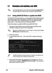
... by simply pressing + during POST to reboot The BIOS information in the drive. 2-2 Chapter 2: BIOS information To use EZ Flash, press + during the Power-On Self Tests (POST). ASUS EZ Flash V1.00 Copyright (C) 2003, ASUSTeK COMPUTER INC. [Onboard BIOS Information] BIOS Version : ASUS P4PE-X/TE ACPI BIOS Revision 1002 BIOS Model : P4PE-X/TE BIOS Built Date : 10/06/03 Please Enter File...
... by simply pressing + during POST to reboot The BIOS information in the drive. 2-2 Chapter 2: BIOS information To use EZ Flash, press + during the Power-On Self Tests (POST). ASUS EZ Flash V1.00 Copyright (C) 2003, ASUSTeK COMPUTER INC. [Onboard BIOS Information] BIOS Version : ASUS P4PE-X/TE ACPI BIOS Revision 1002 BIOS Model : P4PE-X/TE BIOS Built Date : 10/06/03 Please Enter File...

P4PE-X/TE User Manual
Page 35
... a key to update the main BIOS area. DO NOT shutdown or reset the system while updating the BIOS area! Doing so may cause system boot failure. 8. 5. Press to reboot the system with the update process. At the prompt, "Please Enter File Name for the file name that you typed Y. ASUS P4PE-X/TE motherboard user guide 2-3
... a key to update the main BIOS area. DO NOT shutdown or reset the system while updating the BIOS area! Doing so may cause system boot failure. 8. 5. Press to reboot the system with the update process. At the prompt, "Please Enter File Name for the file name that you typed Y. ASUS P4PE-X/TE motherboard user guide 2-3
P4PE-X/TE User Manual
Page 36
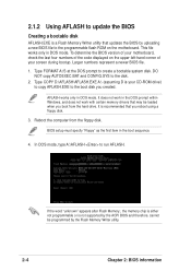
...create a bootable system disk. It does not work with certain memory drivers that may be programmed by the Flash Memory Writer utility. 2-4 Chapter 2: BIOS information BIOS setup must specify "Floppy" as the first item in DOS mode. Type FORMAT A:/S at the DOS prompt to the disk. 2. AFLASH works only.... If the word "unknown" appears after Flash Memory:, the memory chip is either not programmable or is not supported by the ACPI BIOS and therefore, cannot be loaded when you reboot using a floppy disk. 3. Reboot the computer from the hard drive. 2.1.2 Using AFLASH to update...
...create a bootable system disk. It does not work with certain memory drivers that may be programmed by the Flash Memory Writer utility. 2-4 Chapter 2: BIOS information BIOS setup must specify "Floppy" as the first item in DOS mode. Type FORMAT A:/S at the DOS prompt to the disk. 2. AFLASH works only.... If the word "unknown" appears after Flash Memory:, the memory chip is either not programmable or is not supported by the ACPI BIOS and therefore, cannot be loaded when you reboot using a floppy disk. 3. Reboot the computer from the hard drive. 2.1.2 Using AFLASH to update...

P4PE-X/TE User Manual
Page 37
... path, for details) and save to the boot floppy disk you are sure that the new BIOS revision will solve your new BIOS and the path, for example, A:\XXX- The Save Current BIOS To File screen appears. 6. ASUS P4PE-X/TE motherboard user guide 2-5 At the "A:\" prompt, type AFLASH and then press . 4. Select 1. Type the filename of...
... path, for details) and save to the boot floppy disk you are sure that the new BIOS revision will solve your new BIOS and the path, for example, A:\XXX- The Save Current BIOS To File screen appears. 6. ASUS P4PE-X/TE motherboard user guide 2-5 At the "A:\" prompt, type AFLASH and then press . 4. Select 1. Type the filename of...

P4PE-X/TE User Manual
Page 38
... automatically only when necessary. If you encounter problems while updating the new BIOS, DO NOT turn off the system because this happens, call the ASUS service center for support. 2-6 Chapter 2: BIOS information If this may not boot. When prompted to confirm the BIOS update, press Y to the boot disk. The boot block is done...
... automatically only when necessary. If you encounter problems while updating the new BIOS, DO NOT turn off the system because this happens, call the ASUS service center for support. 2-6 Chapter 2: BIOS information If this may not boot. When prompted to confirm the BIOS update, press Y to the boot disk. The boot block is done...
P4PE-X/TE User Manual
Page 39
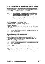
... the support CD that came with the motherboard or a bootable floppy disk that contains the motherboard BIOS (P4PXTE03.AWD) before proceeding with CrashFree BIOS 2 The CrashFree BIOS 2 auto recovery tool allows you may cause system boot failure! ASUS P4PE-X/TE motherboard user guide 2-7 See section "2.1.1 Creating a bootable floppy disk." When the system prompts that contains the...
... the support CD that came with the motherboard or a bootable floppy disk that contains the motherboard BIOS (P4PXTE03.AWD) before proceeding with CrashFree BIOS 2 The CrashFree BIOS 2 auto recovery tool allows you may cause system boot failure! ASUS P4PE-X/TE motherboard user guide 2-7 See section "2.1.1 Creating a bootable floppy disk." When the system prompts that contains the...

P4PE-X/TE User Manual
Page 40
2.1.4 BIOS beep codes When you turn the power on and the system runs POST (Power On Self Tests), you will hear BIOS beeps. Refer to the following table for the meaning of the beeps. Award BIOS Beep Codes Beep One short beep when displaying logo Long beeps in an endless loop One long beep followed by three short beeps High frequency beeps when system is working Meaning No error during POST No DRAM installed or detected Video card not found or video card memory bad CPU overheated; System running at a lower frequency 2-8 Chapter 2: BIOS information
2.1.4 BIOS beep codes When you turn the power on and the system runs POST (Power On Self Tests), you will hear BIOS beeps. Refer to the following table for the meaning of the beeps. Award BIOS Beep Codes Beep One short beep when displaying logo Long beeps in an endless loop One long beep followed by three short beeps High frequency beeps when system is working Meaning No error during POST No DRAM installed or detected Video card not found or video card memory bad CPU overheated; System running at a lower frequency 2-8 Chapter 2: BIOS information
P4PE-X/TE User Manual
Page 41
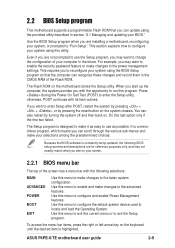
... enable and make changes to change the configuration of your screen. 2.2.1 BIOS menu bar The top of the Flash ROM. Because the BIOS software is highlighted. ASUS P4PE-X/TE motherboard user guide 2-9 Use the BIOS Setup program when you are not prompted to use as easy to configure... your BIOS." You can also restart by pressing the reset button on the ...
... enable and make changes to change the configuration of your screen. 2.2.1 BIOS menu bar The top of the Flash ROM. Because the BIOS software is highlighted. ASUS P4PE-X/TE motherboard user guide 2-9 Use the BIOS Setup program when you are not prompted to use as easy to configure... your BIOS." You can also restart by pressing the reset button on the ...

P4PE-X/TE User Manual
Page 42
...Setup screen is more information to navigate through the entire help document. To exit the help window, press or . 2-10 Chapter 2: BIOS information Use and or the up and down between fields Scrolls backward through the values for the highlighted field Scrolls forward through the values for... the highlighted field Brings up or down arrow keys to the Item Specific Help window, the BIOS setup program also provides a General Help screen. Navigation Key(s) or Left or Right arrow Up or Down arrow - (minus key) + (...
...Setup screen is more information to navigate through the entire help document. To exit the help window, press or . 2-10 Chapter 2: BIOS information Use and or the up and down between fields Scrolls backward through the values for the highlighted field Scrolls forward through the values for... the highlighted field Brings up or down arrow keys to the Item Specific Help window, the BIOS setup program also provides a General Help screen. Navigation Key(s) or Left or Right arrow Up or Down arrow - (minus key) + (...


