
User Manual
Page 2
... you may visit ASUSTeK's home page at: http://www.asus.com.tw/ Products mentioned in this manual may or may not be registered trademarks or copyrights of their respective companies. © Copyright 1996 ASUSTeK Computer Inc. Product Name: P/I-P55T2P4 Product Rev: 2.1 Manual Rev: 2.0 BIOS Version: #401A0-0101 (Displayed on top left during boot...
... you may visit ASUSTeK's home page at: http://www.asus.com.tw/ Products mentioned in this manual may or may not be registered trademarks or copyrights of their respective companies. © Copyright 1996 ASUSTeK Computer Inc. Product Name: P/I-P55T2P4 Product Rev: 2.1 Manual Rev: 2.0 BIOS Version: #401A0-0101 (Displayed on top left during boot...
User Manual
Page 5
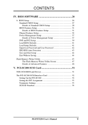
... PCI-SC200 52 Setting the INT Assignment 53 Terminator Settings 53 SCSI ID Numbers 54 P/I-P55T2P4 User's Manual V BIOS Setup 26 Standard CMOS Setup 27 Details of Standard CMOS Setup 28 BIOS Features Setup 31 Details of BIOS Features Setup 31 Chipset Features Setup 34 Power Management Setup 37 Details of Power Management Setup...
... PCI-SC200 52 Setting the INT Assignment 53 Terminator Settings 53 SCSI ID Numbers 54 P/I-P55T2P4 User's Manual V BIOS Setup 26 Standard CMOS Setup 27 Details of Standard CMOS Setup 28 BIOS Features Setup 31 Details of BIOS Features Setup 31 Chipset Features Setup 34 Power Management Setup 37 Details of Power Management Setup...
User Manual
Page 7
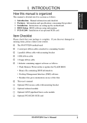
... contact your package is divided into five sections as follows: • Flash Memory Writer utility to update the FLASH BIOS • Binary file containing BIOS information • Desktop Management Interface (DMI) software • Readme files gives instructions on setting up the motherboard. ... √ This user's manual Optional PS/2 mouse cable with mounting bracket Optional infrared module Optional ASUS pipelined burst cache module Optional PCI-SC200 SCSI card P/I . I.INTRODUCTION (Manual/Checklist) I -P55T2P4 User's Manual 1 BIOS Setup: BIOS software setup information. 5.
... contact your package is divided into five sections as follows: • Flash Memory Writer utility to update the FLASH BIOS • Binary file containing BIOS information • Desktop Management Interface (DMI) software • Readme files gives instructions on setting up the motherboard. ... √ This user's manual Optional PS/2 mouse cable with mounting bracket Optional infrared module Optional ASUS pipelined burst cache module Optional PCI-SC200 SCSI card P/I . I.INTRODUCTION (Manual/Checklist) I -P55T2P4 User's Manual 1 BIOS Setup: BIOS software setup information. 5.
User Manual
Page 8
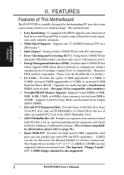
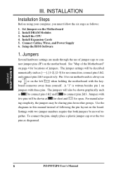
...one PCI/MediaBus 2.0 which allows the use of either an standard PCI card or the ASUS MediaBus Card. • ASUS MediaBus Rev 2.0: Features an expansion slot extension shared with BIOS supports auto detection of hard drives and Plug and Play to make setup of hard ... carefully designed for details.) • L2 Cache: Provides the option of compatibility. (Requires DMI-enabled components. FEATURES Features of This Motherboard The P/I-P55T2P4 is also supported. 2 P/I /O subsystems. • Error Checking and Correcting (ECC): Using Intel's 430HX PCIset and parity DRAM modules can also...
...one PCI/MediaBus 2.0 which allows the use of either an standard PCI card or the ASUS MediaBus Card. • ASUS MediaBus Rev 2.0: Features an expansion slot extension shared with BIOS supports auto detection of hard drives and Plug and Play to make setup of hard ... carefully designed for details.) • L2 Cache: Provides the option of compatibility. (Requires DMI-enabled components. FEATURES Features of This Motherboard The P/I-P55T2P4 is also supported. 2 P/I /O subsystems. • Error Checking and Correcting (ECC): Using Intel's 430HX PCIset and parity DRAM modules can also...
User Manual
Page 9
... Flash ROM 3 PCI Slots Super Multi-I/O PCI 4 or ASUS MediaBus 2.0 72-pin SIMM Sockets Intel's 430HX PCIset CPU ZIF Socket 7 L2 Upgrade Cache Expansion Slot On-Board 256KB/ 512KB Pipelined Burst L2 Cache P/I-P55T2P4 User's Manual 3 BIOS supports IDE CD-ROM boot-up. • Optional IrDA and... PS/2: This motherboard supports an optional infrared port module for wireless interface and a PS/2 mouse cable set. • NCR SCSI BIOS: This motherboard has firmware that supports...
... Flash ROM 3 PCI Slots Super Multi-I/O PCI 4 or ASUS MediaBus 2.0 72-pin SIMM Sockets Intel's 430HX PCIset CPU ZIF Socket 7 L2 Upgrade Cache Expansion Slot On-Board 256KB/ 512KB Pipelined Burst L2 Cache P/I-P55T2P4 User's Manual 3 BIOS supports IDE CD-ROM boot-up. • Optional IrDA and... PS/2: This motherboard supports an optional infrared port module for wireless interface and a PS/2 mouse cable set. • NCR SCSI BIOS: This motherboard has firmware that supports...
User Manual
Page 12
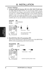
Setup the BIOS Software 1. nect jumper pins (JP) on the Motherboard 2. Pin 1 for our motherboards is written besides pin 1 on the left when holding the motherboard with two ... away from other groups. Jumpers with the key- III. The jumpers will be shown graphically such as [----], [1-2], [2-3] for locations of jumper caps to - INSTALLATION (Jumpers) 6 P/I-P55T2P4 User's Manual Install Expansion Cards 5. Settings with three pins. To connect the pins, simply place a plastic jumper cap over the two pins as follows: 1. Install...
Setup the BIOS Software 1. nect jumper pins (JP) on the Motherboard 2. Pin 1 for our motherboards is written besides pin 1 on the left when holding the motherboard with two ... away from other groups. Jumpers with the key- III. The jumpers will be shown graphically such as [----], [1-2], [2-3] for locations of jumper caps to - INSTALLATION (Jumpers) 6 P/I-P55T2P4 User's Manual Install Expansion Cards 5. Settings with three pins. To connect the pins, simply place a plastic jumper cap over the two pins as follows: 1. Install...
User Manual
Page 14
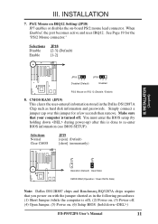
...-I/O SMC37C669, you can selectively disable each onboard Multi-I/O item (floppy, serial, parallel, and IrDA) through BIOS (see page 35) or disable all Multi-I /O, the following jumper in the Enabled position. Flash ROM Boot... Block Programming (JP8) This sets the operation mode of the boot block area of the BIOS Flash ROM to allow programming in order to use your motherboard does not use the above SMC...not be available and you can only disabled each item through BIOS. INSTALLATION (Jumpers) III. Selections Enable Disable JP1 [1-2] (Default) [2-3] JP 1 1 2 3 Enable (Default) JP...
...-I/O SMC37C669, you can selectively disable each onboard Multi-I/O item (floppy, serial, parallel, and IrDA) through BIOS (see page 35) or disable all Multi-I /O, the following jumper in the Enabled position. Flash ROM Boot... Block Programming (JP8) This sets the operation mode of the boot block area of the BIOS Flash ROM to allow programming in order to use your motherboard does not use the above SMC...not be available and you can only disabled each item through BIOS. INSTALLATION (Jumpers) III. Selections Enable Disable JP1 [1-2] (Default) [2-3] JP 1 1 2 3 Enable (Default) JP...
User Manual
Page 17
... power-up) after this jumper for the "PS/2 Mouse connector." INSTALLATION 7. See Page 19 for a few seconds then remove. You must enter the BIOS setup (by holding down ) P/I-P55T2P4 User's Manual 11 Selections Normal Clear CMOS JP19 [open] (Default) [short] (momentarily) JP JP 19 19 Operation (Default) Clear Data CMOS RAM (Operation...
... power-up) after this jumper for the "PS/2 Mouse connector." INSTALLATION 7. See Page 19 for a few seconds then remove. You must enter the BIOS setup (by holding down ) P/I-P55T2P4 User's Manual 11 Selections Normal Clear CMOS JP19 [open] (Default) [short] (momentarily) JP JP 19 19 Operation (Default) Clear Data CMOS RAM (Operation...
User Manual
Page 18
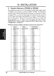
.... The DRAM can be either 60ns or 70ns Fast Page Mode (Asymmetric or Symmetric) or EDO. Install two memory modules each time as shown in BIOS Chipset Setup "Auto Configuration" on page 35. III. Bank 0 Slots 1 & 2 4MB x 2 8MB x 2 16MB x 2 32MB x 2 64MB x 2 4MB x 2 4MB x 2 4MB x 2 4MB x 2 4MB x 2 8MB x 2 8MB x 2 8MB x 2 8MB x 2 8MB... 24MB 40MB 72MB 136MB 24MB 32MB 48MB 80MB 144MB 40MB 48MB 64MB 96MB 160MB 72MB 80MB 96MB 128MB 192MB 136MB 144MB 160MB 192MB 256MB 12 P/I-P55T2P4 User's Manual
.... The DRAM can be either 60ns or 70ns Fast Page Mode (Asymmetric or Symmetric) or EDO. Install two memory modules each time as shown in BIOS Chipset Setup "Auto Configuration" on page 35. III. Bank 0 Slots 1 & 2 4MB x 2 8MB x 2 16MB x 2 32MB x 2 64MB x 2 4MB x 2 4MB x 2 4MB x 2 4MB x 2 4MB x 2 8MB x 2 8MB x 2 8MB x 2 8MB x 2 8MB... 24MB 40MB 72MB 136MB 24MB 32MB 48MB 80MB 144MB 40MB 48MB 64MB 96MB 160MB 72MB 80MB 96MB 128MB 192MB 136MB 144MB 160MB 192MB 256MB 12 P/I-P55T2P4 User's Manual

User Manual
Page 22
... any necessary jumpers on any hardware and software settings that may be exclusively assigned to use at the same time. 16 P/I-P55T2P4 User's Manual Remove your expansion card. 2. Setup the BIOS if necessary. 9. Currently, there are already in use Microsoft's Diagnostic (MSD.EXE) utility included in the Windows directory to setup your...
... any necessary jumpers on any hardware and software settings that may be exclusively assigned to use at the same time. 16 P/I-P55T2P4 User's Manual Remove your expansion card. 2. Setup the BIOS if necessary. 9. Currently, there are already in use Microsoft's Diagnostic (MSD.EXE) utility included in the Windows directory to setup your...
User Manual
Page 23
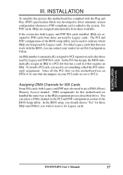
... the jumpers on this motherboard use a DMA (Direct Memory Access) channel. INSTALLATION (DMAChannels) P/I-P55T2P4 User's Manual 17 An IRQ number is added to INT A. In the PCI bus design, the BIOS automatically assigns an IRQ to indicate which was developed to allow automatic system configuration whenever a PNP-...use an INTA #, be used by Legacy cards. You can select a DMA channel in the PCI and PNP configuration section of the BIOS setup utility can contact your PCI cards are assigned automatically from those IRQ's and DMA's you can be sure that requires an IRQ. ...
... the jumpers on this motherboard use a DMA (Direct Memory Access) channel. INSTALLATION (DMAChannels) P/I-P55T2P4 User's Manual 17 An IRQ number is added to INT A. In the PCI bus design, the BIOS automatically assigns an IRQ to indicate which was developed to allow automatic system configuration whenever a PNP-...use an INTA #, be used by Legacy cards. You can select a DMA channel in the PCI and PNP configuration section of the BIOS setup utility can contact your PCI cards are assigned automatically from those IRQ's and DMA's you can be sure that requires an IRQ. ...

User Manual
Page 26
... You can enable the parallel port and choose the IRQ through BIOS Setup on the mounting bracket will then be available for pointing devices or other serial devices. III. INSTALLATION (Connectors) 20 P/I-P55T2P4 User's Manual It will then be connected to the case on... (Two 10-pin blocks) These connectors support the provided serial port ribbon cables with mounting bracket. Parallel Printer Connector (26 Pin Block) Connection for BIOS configuration of "Onboard Serial Port" COM 1 COM 2 Pin 1 Pin 1 III. INSTALLATION 3. Note: Serial printers must be used for a parallel...
... You can enable the parallel port and choose the IRQ through BIOS Setup on the mounting bracket will then be available for pointing devices or other serial devices. III. INSTALLATION (Connectors) 20 P/I-P55T2P4 User's Manual It will then be connected to the case on... (Two 10-pin blocks) These connectors support the provided serial port ribbon cables with mounting bracket. Parallel Printer Connector (26 Pin Block) Connection for BIOS configuration of "Onboard Serial Port" COM 1 COM 2 Pin 1 Pin 1 III. INSTALLATION 3. Note: Serial printers must be used for a parallel...

User Manual
Page 29
...GND SMI Lead GND Reset SW GND +5V NC Power LED & GND LOCK Keyboard Lock GND +5V GND Speaker GND Connector SPKR System Case Connections P/I-P55T2P4 User's Manual 23 If you do not have a switch for rebooting your computer without having to turn off your power switch This is a preferred ... the Power LED from the system case to open moment and therefore leaving it shorted will be instantly decreased to prolong the life of the BIOS software should be controlled by settings in the POWER MANAGEMENT SETUP of the system's power supply. The turbo LED connection is labeled here but...
...GND SMI Lead GND Reset SW GND +5V NC Power LED & GND LOCK Keyboard Lock GND +5V GND Speaker GND Connector SPKR System Case Connections P/I-P55T2P4 User's Manual 23 If you do not have a switch for rebooting your computer without having to turn off your power switch This is a preferred ... the Power LED from the system case to open moment and therefore leaving it shorted will be instantly decreased to prolong the life of the BIOS software should be controlled by settings in the POWER MANAGEMENT SETUP of the system's power supply. The turbo LED connection is labeled here but...

User Manual
Page 31
...from the time you turn on system cases that may be supplied may have five or ten pins (for instructions. Your system power 6. P/I-P55T2P4 User's Manual 25 NC GND +5V IRRX IRTX Front View Back View Infrared Module Connector IRTX +5V GND NC IRRX III. You may ... an power outlet that all jumpers and connections are running, additional messages will then run power-on test. This module mounts to enter BIOS setup. The ribbon cable that support this feature. IrDA-compliant infrared module connector (IR) This connector supports the optional wireless transmitting and...
...from the time you turn on system cases that may be supplied may have five or ten pins (for instructions. Your system power 6. P/I-P55T2P4 User's Manual 25 NC GND +5V IRRX IRTX Front View Back View Infrared Module Connector IRTX +5V GND NC IRRX III. You may ... an power outlet that all jumpers and connections are running, additional messages will then run power-on test. This module mounts to enter BIOS setup. The ribbon cable that support this feature. IrDA-compliant infrared module connector (IR) This connector supports the optional wireless transmitting and...
User Manual
Page 32
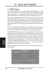
... and settings. If so, invoke the Setup utility, as described in detail on again. Press the key to run this utility. BIOS SOFTWARE 6. BIOS Setup The motherboard supports two programmable Flash ROM chips: 5 Volt and 12 Volt. If you are a little bit late pressing the... will need to configure your motherboard came in particular, the hard disk specifications. When you from calling up the Setup utility. BIOS (BIOS Setup) 26 P/I-P55T2P4 User's Manual This section describes how to call up Setup. When you with the following options: IV. All computer motherboards provide...
... and settings. If so, invoke the Setup utility, as described in detail on again. Press the key to run this utility. BIOS SOFTWARE 6. BIOS Setup The motherboard supports two programmable Flash ROM chips: 5 Volt and 12 Volt. If you are a little bit late pressing the... will need to configure your motherboard came in particular, the hard disk specifications. When you from calling up the Setup utility. BIOS (BIOS Setup) 26 P/I-P55T2P4 User's Manual This section describes how to call up Setup. When you with the following options: IV. All computer motherboards provide...
User Manual
Page 33
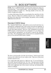
...color. Another section just below the control keys section displays information on the other hand, is read-only and automatically adjusts accordingly. P/I-P55T2P4 User's Manual 27 Standard CMOS Setup This "Standard CMOS Setup" option allows you will not need information on this option anymore. The... values usually get lost or damaged, or if you change your system hardware configuration, you to select this screen. BIOS SOFTWARE NOTE: The "Load BIOS Defaults" option loads the minimized settings for regular use on the selected field, press the key. The help menu will...
...color. Another section just below the control keys section displays information on the other hand, is read-only and automatically adjusts accordingly. P/I-P55T2P4 User's Manual 27 Standard CMOS Setup This "Standard CMOS Setup" option allows you will not need information on this option anymore. The... values usually get lost or damaged, or if you change your system hardware configuration, you to select this screen. BIOS SOFTWARE NOTE: The "Load BIOS Defaults" option loads the minimized settings for regular use on the selected field, press the key. The help menu will...
User Manual
Page 34
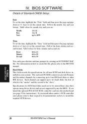
... to their respective documentations on how to modify the current You can bypass the date and time prompts by any the BIOS. If you install other IDE devices. BIOS (Standard CMOS) 28 P/I-P55T2P4 User's Manual Follow the month, day and year format. Hard Disks This field records the specifications for instructions). the first... be entered here since they operate using device drivers and are not supported by creating an AUTOEXEC.BAT file. keys to the MS-DOS manual. BIOS SOFTWARE Details of which is the "master" and the second is the "slave".
... to their respective documentations on how to modify the current You can bypass the date and time prompts by any the BIOS. If you install other IDE devices. BIOS (Standard CMOS) 28 P/I-P55T2P4 User's Manual Follow the month, day and year format. Hard Disks This field records the specifications for instructions). the first... be entered here since they operate using device drivers and are not supported by creating an AUTOEXEC.BAT file. keys to the MS-DOS manual. BIOS SOFTWARE Details of which is the "master" and the second is the "slave".

User Manual
Page 35
BIOS SOFTWARE To enter specifications for MFM and ESDI drives. To select, simply press the or key to the Normal for IDE hard disk drives smaller ... provided predefined drive specifications. If you can be used with the power off) and then power on page 30. Large type of sectors) and MODE. BIOS (StandardCMOS) P/I-P55T2P4 User's Manual 29
BIOS SOFTWARE To enter specifications for MFM and ESDI drives. To select, simply press the or key to the Normal for IDE hard disk drives smaller ... provided predefined drive specifications. If you can be used with the power off) and then power on page 30. Large type of sectors) and MODE. BIOS (StandardCMOS) P/I-P55T2P4 User's Manual 29

User Manual
Page 36
...A Drive B Both Disabled (Default) Video Set this field to halt. or right-arrow key. This is the Japanese standard floppy drive. BIOS SOFTWARE Drive A, Drive B These fields record the types of errors will cause the system to the type of video display card installed in..., 5.25 in. 1.2MB, 5.25 in. 720KB, 3.5 in. 1.44MB, 3.5 in. 2.88MB, 3.5 in a 3.5" diskette. The standard stores 1.2MB in . BIOS (Standard CMOS) 30 P/I-P55T2P4 User's Manual IV. The options are: EGA/VGA (Default) Mono (for a particular drive, highlight its corresponding field and then select the drive type using...
...A Drive B Both Disabled (Default) Video Set this field to halt. or right-arrow key. This is the Japanese standard floppy drive. BIOS SOFTWARE Drive A, Drive B These fields record the types of errors will cause the system to the type of video display card installed in..., 5.25 in. 1.2MB, 5.25 in. 720KB, 3.5 in. 1.44MB, 3.5 in. 2.88MB, 3.5 in a 3.5" diskette. The standard stores 1.2MB in . BIOS (Standard CMOS) 30 P/I-P55T2P4 User's Manual IV. The options are: EGA/VGA (Default) Mono (for a particular drive, highlight its corresponding field and then select the drive type using...

User Manual
Page 37
... If you need information on a particular entry, highlight it and then press the key. This setting is "Disabled". BIOS SOFTWARE BIOS Features Setup This "BIOS Features Setup" option consists of new operating systems require that allow the operation to continue or use . If this to ... remain in their respective uses. and load the BIOS default values and Setup default values, respectively. Details of BIOS Features Setup: Virus Warning This field protects the boot sector and partition table of your preference. IV. P/I-P55T2P4 User's Manual 31 A pop-up some system ...
... If you need information on a particular entry, highlight it and then press the key. This setting is "Disabled". BIOS SOFTWARE BIOS Features Setup This "BIOS Features Setup" option consists of new operating systems require that allow the operation to continue or use . If this to ... remain in their respective uses. and load the BIOS default values and Setup default values, respectively. Details of BIOS Features Setup: Virus Warning This field protects the boot sector and partition table of your preference. IV. P/I-P55T2P4 User's Manual 31 A pop-up some system ...


