User Manual
Page 3
... Unit 1-3 1.3.3 ASUS Innovative Design 1-3 1.3.4 ASUS unique features 1-3 Chapter 2: Hardware information 2.1 Before you proceed 2-1 2.2 Motherboard overview 2-2 2.2.1 Motherboard layout 2-2 2.2.2 Central ...Motherboard installation 2-27 2.3.6 ATX Power connection 2-29 2.3.7 SATA device connection 2-30 2.3.8 Expansion Card installation 2-31 2.3.9 Rear panel connection 2-32 2.3.10 Audio I/O connections 2-34 2.4 Starting up for the first time 2-36 2.5 Turning off the computer 2-36 iii Contents Notices...vi Safety information...vii About this guide...viii M5A97...
... Unit 1-3 1.3.3 ASUS Innovative Design 1-3 1.3.4 ASUS unique features 1-3 Chapter 2: Hardware information 2.1 Before you proceed 2-1 2.2 Motherboard overview 2-2 2.2.1 Motherboard layout 2-2 2.2.2 Central ...Motherboard installation 2-27 2.3.6 ATX Power connection 2-29 2.3.7 SATA device connection 2-30 2.3.8 Expansion Card installation 2-31 2.3.9 Rear panel connection 2-32 2.3.10 Audio I/O connections 2-34 2.4 Starting up for the first time 2-36 2.5 Turning off the computer 2-36 iii Contents Notices...vi Safety information...vii About this guide...viii M5A97...

User Manual
Page 18
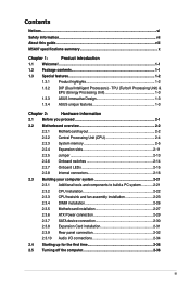
Chapter 2 2.2 Motherboard overview 2.2.1 Motherboard layout 1 2 3 1 4 22.9cm(9.0in) KBMS USB3_12 EATX12V CHA_FAN2 CPU_FAN PWR_FAN EPU ASM 1042 SPDIF_O2 5 USB56 SOCKET AM3+ DDR3 DIMM_A1 (64bit, 240-pin module) DDR3 DIMM_A2 (....0in) USB34 LAN1_USB12 MemOK! 6 AUDIO AMD® 970 CHA_FAN1 RTL 8111E PCIEX16_1 2 EATXPWR Super I/O TPU PCIEX1_1 PCIEX1_2 ICS 9LPRS477 Lithium Cell CMOS Power M5A97 PCIEX16_2 SATA6G_6 AMD® SATA6G_5 7 SB950 ALC 887 SPDIF_OUT AAFP PCI1 8 SB_PWR 32Mb BIOS SATA6G_2 SATA6G_4 PCI2 COM1 USB1112 USB910 USB78 CLRTC SATA6G_1 SATA6G_3 PANEL...
Chapter 2 2.2 Motherboard overview 2.2.1 Motherboard layout 1 2 3 1 4 22.9cm(9.0in) KBMS USB3_12 EATX12V CHA_FAN2 CPU_FAN PWR_FAN EPU ASM 1042 SPDIF_O2 5 USB56 SOCKET AM3+ DDR3 DIMM_A1 (64bit, 240-pin module) DDR3 DIMM_A2 (....0in) USB34 LAN1_USB12 MemOK! 6 AUDIO AMD® 970 CHA_FAN1 RTL 8111E PCIEX16_1 2 EATXPWR Super I/O TPU PCIEX1_1 PCIEX1_2 ICS 9LPRS477 Lithium Cell CMOS Power M5A97 PCIEX16_2 SATA6G_6 AMD® SATA6G_5 7 SB950 ALC 887 SPDIF_OUT AAFP PCI1 8 SB_PWR 32Mb BIOS SATA6G_2 SATA6G_4 PCI2 COM1 USB1112 USB910 USB78 CLRTC SATA6G_1 SATA6G_3 PANEL...

User Manual
Page 43
The motherboard layout may vary with models, but the installation steps remain the same. 2 Chapter 2 ASUS M5A97 2-27 2.3.5 1 Motherboard installation The diagrams in this section are for reference only.
The motherboard layout may vary with models, but the installation steps remain the same. 2 Chapter 2 ASUS M5A97 2-27 2.3.5 1 Motherboard installation The diagrams in this section are for reference only.

User Manual
Page 108
... Chapter 2 in place. Connect a VGA or a DVI cable to the two graphics cards separately. 6. The graphics cards and the motherboard layout may vary with graphics cards) 5. Ensure that the connector is firmly in this user manual for the locations of the PCIEX16 slots recommended...that the cards are for multi-graphics card installation. 3. goldfingers 5-2 Chapter 5: ATI® Quad-GPU CrossFireX™ technology support If your motherboard has more than two PCIEX16 slots, refer to the goldfingers on the slots. 4. CrossFireX bridge (bundled with models, but the installation steps...
... Chapter 2 in place. Connect a VGA or a DVI cable to the two graphics cards separately. 6. The graphics cards and the motherboard layout may vary with graphics cards) 5. Ensure that the connector is firmly in this user manual for the locations of the PCIEX16 slots recommended...that the cards are for multi-graphics card installation. 3. goldfingers 5-2 Chapter 5: ATI® Quad-GPU CrossFireX™ technology support If your motherboard has more than two PCIEX16 slots, refer to the goldfingers on the slots. 4. CrossFireX bridge (bundled with models, but the installation steps...


