
User Manual
Page 13
...! Thank you start installing the motherboard, and hardware devices on it another standout in your package with different models. ASUS M5A97 1-1 Actual product specifications may vary with the list below. 1.2 Package contents Check your motherboard package for reference only. Chapter 1 Chapter 1: Chapter 1 Product introduction 1.1 Welcome! The... line of the above items is damaged or missing, contact your retailer. • The illustrated items above are for the following items. User Manual ASUS M5A97 motherboard User guide Support DVD 2 x Serial ATA 6.0 Gb/s cables...
...! Thank you start installing the motherboard, and hardware devices on it another standout in your package with different models. ASUS M5A97 1-1 Actual product specifications may vary with the list below. 1.2 Package contents Check your motherboard package for reference only. Chapter 1 Chapter 1: Chapter 1 Product introduction 1.1 Welcome! The... line of the above items is damaged or missing, contact your retailer. • The illustrated items above are for the following items. User Manual ASUS M5A97 motherboard User guide Support DVD 2 x Serial ATA 6.0 Gb/s cables...

User Manual
Page 15
... optimize performance under varied system conditions. MemOK! quickly ensures memory boot compatibility. ASUS Quiet Thermal Solutions ASUS Quiet Thermal solution makes system more stable and enhances the overclocking capability. determines ...ASUS vision of creating environment-friendly and energyefficient products through product design and innovation to reduce carbon footprint of the button to energy consumptions. Chapter 1 ErP ready The motherboard is in different geographic regions and your PC's loading. The built-in regards to patch memory issues. MemOK! ASUS M5A97...
... optimize performance under varied system conditions. MemOK! quickly ensures memory boot compatibility. ASUS Quiet Thermal Solutions ASUS Quiet Thermal solution makes system more stable and enhances the overclocking capability. determines ...ASUS vision of creating environment-friendly and energyefficient products through product design and innovation to reduce carbon footprint of the button to energy consumptions. Chapter 1 ErP ready The motherboard is in different geographic regions and your PC's loading. The built-in regards to patch memory issues. MemOK! ASUS M5A97...

User Manual
Page 17
Chapter 2 ASUS M5A97 2-1 Chapter 2: Chapter 2 Hardware information 2.1 Before you proceed Take note of the following precautions before touching any component. • Before handling components, use a grounded wrist strap ...
Chapter 2 ASUS M5A97 2-1 Chapter 2: Chapter 2 Hardware information 2.1 Before you proceed Take note of the following precautions before touching any component. • Before handling components, use a grounded wrist strap ...
User Manual
Page 19
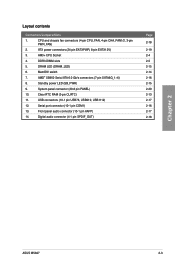
... RTC RAM (3-pin CLRTC) 11. MemOK! Digital audio connector (4-1 pin SPDIF_OUT) Page 2-18 2-19 2-4 2-5 2-15 2-14 2-16 2-15 2-20 2-13 2-17 2-16 2-17 2-18 Chapter 2 ASUS M5A97 2-3 DDR3 DIMM slots 5. System panel connector (20-8 pin PANEL) 10. Standby power LED (SB_PWR) 9. Serial port connector (10-1 pin COM1) 13. Layout contents Connectors/Jumpers...
... RTC RAM (3-pin CLRTC) 11. MemOK! Digital audio connector (4-1 pin SPDIF_OUT) Page 2-18 2-19 2-4 2-5 2-15 2-14 2-16 2-15 2-20 2-13 2-17 2-16 2-17 2-18 Chapter 2 ASUS M5A97 2-3 DDR3 DIMM slots 5. System panel connector (20-8 pin PANEL) 10. Standby power LED (SB_PWR) 9. Serial port connector (10-1 pin COM1) 13. Layout contents Connectors/Jumpers...
User Manual
Page 21
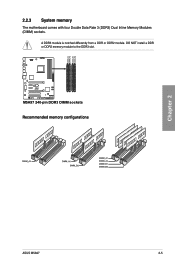
M5A97 M5A97 240-pin DDR3 DIMM sockets Recommended memory configurations ASUS M5A97 2-5 A DDR3 module is notched differently from a DDR or DDR2 module. DO NOT install a DDR or DDR2 memory module to the DDR3 slot. DIMM_A1 DIMM_A2 DIMM_B1 DIMM_B2 Chapter 2 2.2.3 System memory The motherboard comes with four Double Data Rate 3 (DDR3) Dual Inline Memory Modules (DIMM) sockets.
M5A97 M5A97 240-pin DDR3 DIMM sockets Recommended memory configurations ASUS M5A97 2-5 A DDR3 module is notched differently from a DDR or DDR2 module. DO NOT install a DDR or DDR2 memory module to the DDR3 slot. DIMM_A1 DIMM_A2 DIMM_B1 DIMM_B2 Chapter 2 2.2.3 System memory The motherboard comes with four Double Data Rate 3 (DDR3) Dual Inline Memory Modules (DIMM) sockets.

User Manual
Page 23
...Brand - - - - DIMM socket support (Optional) 1 DIMM 2 DIMM 4 DIMM • • • • • • • • • • • M5A97 Motherboard Qualified Vendors Lists (QVL) DDR3 1800MHz capability for AMD AM3+ CPU Vendors Part No. Timing Voltage - 9-9-9-24 1.55~1.75 - 7-9-7-21 1.55~1.75 - 8-8-8-24 1.5 - 9-9-9-24...8226; • • • • • • • • • • • • • • • • • • • ASUS M5A97 2-7 Size SS/DS Chip Brand Chip NO.
...Brand - - - - DIMM socket support (Optional) 1 DIMM 2 DIMM 4 DIMM • • • • • • • • • • • M5A97 Motherboard Qualified Vendors Lists (QVL) DDR3 1800MHz capability for AMD AM3+ CPU Vendors Part No. Timing Voltage - 9-9-9-24 1.55~1.75 - 7-9-7-21 1.55~1.75 - 8-8-8-24 1.5 - 9-9-9-24...8226; • • • • • • • • • • • • • • • • • • • ASUS M5A97 2-7 Size SS/DS Chip Brand Chip NO.

User Manual
Page 27
Chapter 2 M5A97 Slot No. Slot Description 1 PCIe 2.0 x16_1 slot [blue] (at x16 mode) 2 PCIe 2.0 x1_1 slot 3 PCIe 2.0 x1_2 slot 4 PCIe 2.0 x16_2 slot [black] (at x4 mode) 5 PCI slot 1 6 PCI slot 2 VGA configuration Single VGA/PCIe card Dual VGA/PCIe card PCI Express operating mode PCIe 2.0 x16_1 x16 (Recommend for single VGA) x16 PCIe 2.0 x16_2 N/A x4 ASUS M5A97 2-11 Failure to unplug the power cord before adding or removing expansion cards. 2.2.4 Expansion slots Ensure to do so may cause you physical injury and damage motherboard components.
Chapter 2 M5A97 Slot No. Slot Description 1 PCIe 2.0 x16_1 slot [blue] (at x16 mode) 2 PCIe 2.0 x1_1 slot 3 PCIe 2.0 x1_2 slot 4 PCIe 2.0 x16_2 slot [black] (at x4 mode) 5 PCI slot 1 6 PCI slot 2 VGA configuration Single VGA/PCIe card Dual VGA/PCIe card PCI Express operating mode PCIe 2.0 x16_1 x16 (Recommend for single VGA) x16 PCIe 2.0 x16_2 N/A x4 ASUS M5A97 2-11 Failure to unplug the power cord before adding or removing expansion cards. 2.2.4 Expansion slots Ensure to do so may cause you physical injury and damage motherboard components.
User Manual
Page 29
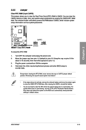
.... After clearing the CMOS, reinstall the battery. • You do not help, remove the onboard battery and move the cap back to re-enter data. ASUS M5A97 2-13 Hold down and reboot the system so the BIOS can clear the CMOS memory of date, time, and system setup parameters by erasing the... CMOS RTC RAM data. M5A97 M5A97 Clear RTC RAM CLRTC 12 23 Normal (Default) Clear RTC To erase the RTC RAM 1. Except when clearing the RTC RAM, never remove the cap...
.... After clearing the CMOS, reinstall the battery. • You do not help, remove the onboard battery and move the cap back to re-enter data. ASUS M5A97 2-13 Hold down and reboot the system so the BIOS can clear the CMOS memory of date, time, and system setup parameters by erasing the... CMOS RTC RAM data. M5A97 M5A97 Clear RTC RAM CLRTC 12 23 Normal (Default) Clear RTC To erase the RTC RAM 1. Except when clearing the RTC RAM, never remove the cap...
User Manual
Page 31
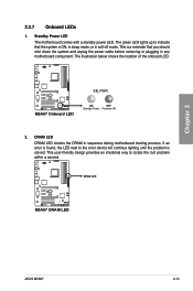
DRAM LED M5A97 M5A97 DRAM LED ASUS M5A97 2-15 This user-friendly design provides an intuitional way to the error device will continue lighting until the problem is a reminder that the system is ...;off mode. If an error is ON, in sleep mode, or in any motherboard component. Standby Power LED The motherboard comes with a standby power LED. M5A97 M5A97 Onboard LED SB_PWR ON OFF Standby Power Powered Off 2. DRAM LED DRAM LED checks the DRAM in sequence during motherboard booting process. Chapter 2 2.2.7 Onboard LEDs...
DRAM LED M5A97 M5A97 DRAM LED ASUS M5A97 2-15 This user-friendly design provides an intuitional way to the error device will continue lighting until the problem is a reminder that the system is ...;off mode. If an error is ON, in sleep mode, or in any motherboard component. Standby Power LED The motherboard comes with a standby power LED. M5A97 M5A97 Onboard LED SB_PWR ON OFF Standby Power Powered Off 2. DRAM LED DRAM LED checks the DRAM in sequence during motherboard booting process. Chapter 2 2.2.7 Onboard LEDs...

User Manual
Page 33
... NC NC NC AAFP PIN 1 PIN 1 MIC2 MICPWR Line out_R NC Line out_L PORT1 L PORT1 R PORT2 R SENSE_SEND PORT2 L M5A97 HD-audio-compliant pin definition M5A97 Front panel audio connector Legacy AC'97 compliant definition • We recommend that supports up to [HD Audio]; if you want to ...Front panel audio connector (10-1 pin AAFP) This connector is for USB 2.0 ports. Refer to the USB connectors. USB 2.0 connectors (10-1 pin USB78; ASUS M5A97 2-17 Chapter 2 USB1112 USB910 USB78 USB+5V USB_P14USB_P14+ GND NC USB+5V USB_P12USB_P12+ GND NC USB+5V USB_P10USB_P10+ GND NC...
... NC NC NC AAFP PIN 1 PIN 1 MIC2 MICPWR Line out_R NC Line out_L PORT1 L PORT1 R PORT2 R SENSE_SEND PORT2 L M5A97 HD-audio-compliant pin definition M5A97 Front panel audio connector Legacy AC'97 compliant definition • We recommend that supports up to [HD Audio]; if you want to ...Front panel audio connector (10-1 pin AAFP) This connector is for USB 2.0 ports. Refer to the USB connectors. USB 2.0 connectors (10-1 pin USB78; ASUS M5A97 2-17 Chapter 2 USB1112 USB910 USB78 USB+5V USB_P14USB_P14+ GND NC USB+5V USB_P12USB_P12+ GND NC USB+5V USB_P10USB_P10+ GND NC...

User Manual
Page 35
... EATX12 V power plug; otherwise, the system will not boot. • We recommend that complies with more power-consuming devices. Chapter 2 ASUS M5A97 2-19 7. Find the proper orientation and push down firmly until the connectors completely fit. EATX12V EATXPWR +12V DC +12V DC +12V DC +...12V DC M5A97 M5A97 ATX power connectors GND GND GND GND +3 Volts +12 Volts +12 Volts +5V Standby Power OK PIN 1 GND +5 Volts GND +5 Volts ...
... EATX12 V power plug; otherwise, the system will not boot. • We recommend that complies with more power-consuming devices. Chapter 2 ASUS M5A97 2-19 7. Find the proper orientation and push down firmly until the connectors completely fit. EATX12V EATXPWR +12V DC +12V DC +12V DC +...12V DC M5A97 M5A97 ATX power connectors GND GND GND GND +3 Volts +12 Volts +12 Volts +5V Standby Power OK PIN 1 GND +5 Volts GND +5 Volts ...

User Manual
Page 37
Chapter 2 2.3 Building your computer system 2.3.1 Additional tools and components to build a PC system 1 bag of screws Philips (cross) screwdriver PC chassis Power supply unit AMD AM3+ CPU AMD AM3+ compatible CPU Fan DIMM SATA hard disk drive SATA optical disc drive (optional) Graphics card (optional) The tools and components in the table above are not included in the motherboard package. ASUS M5A97 2-21
Chapter 2 2.3 Building your computer system 2.3.1 Additional tools and components to build a PC system 1 bag of screws Philips (cross) screwdriver PC chassis Power supply unit AMD AM3+ CPU AMD AM3+ compatible CPU Fan DIMM SATA hard disk drive SATA optical disc drive (optional) Graphics card (optional) The tools and components in the table above are not included in the motherboard package. ASUS M5A97 2-21
User Manual
Page 39
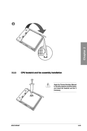
3 Chapter 2 2.3.3 CPU heatsink and fan assembly installation Apply the Thermal Interface Material to the CPU heatsink and CPU before you install the heatsink and fan if necessary. ASUS M5A97 2-23
3 Chapter 2 2.3.3 CPU heatsink and fan assembly installation Apply the Thermal Interface Material to the CPU heatsink and CPU before you install the heatsink and fan if necessary. ASUS M5A97 2-23

User Manual
Page 43
2.3.5 1 Motherboard installation The diagrams in this section are for reference only. The motherboard layout may vary with models, but the installation steps remain the same. 2 Chapter 2 ASUS M5A97 2-27
2.3.5 1 Motherboard installation The diagrams in this section are for reference only. The motherboard layout may vary with models, but the installation steps remain the same. 2 Chapter 2 ASUS M5A97 2-27

User Manual
Page 45
2.3.6 1 ATX Power connection 2 OR OR Chapter 2 ASUS M5A97 2-29
2.3.6 1 ATX Power connection 2 OR OR Chapter 2 ASUS M5A97 2-29

User Manual
Page 47
2.3.8 Expansion Card installation To install PCIe x16 cards To install PCIe x1 cards To install PCI cards Chapter 2 ASUS M5A97 2-31
2.3.8 Expansion Card installation To install PCIe x16 cards To install PCIe x1 cards To install PCI cards Chapter 2 ASUS M5A97 2-31

User Manual
Page 49
... In - ACT/LINK SPEED LED LED LAN port 8-channel Line In Front Speaker Out Mic In Center/Subwoofer Rear Speaker Out Side Speaker Out Chapter 2 ASUS M5A97 2-33 Rear Speaker Out - 6-channel Line In Front Speaker Out Mic In Center/Subwoofer Rear Speaker Out -
... In - ACT/LINK SPEED LED LED LAN port 8-channel Line In Front Speaker Out Mic In Center/Subwoofer Rear Speaker Out Side Speaker Out Chapter 2 ASUS M5A97 2-33 Rear Speaker Out - 6-channel Line In Front Speaker Out Mic In Center/Subwoofer Rear Speaker Out -

User Manual
Page 51
Connect to 4.1 channel Speakers Connect to 5.1 channel Speakers Chapter 2 Connect to 7.1 channel Speakers ASUS M5A97 2-35
Connect to 4.1 channel Speakers Connect to 5.1 channel Speakers Chapter 2 Connect to 7.1 channel Speakers ASUS M5A97 2-35

User Manual
Page 53
Chapter 3: Chapter 3 BIOS setup 3.1 Knowing BIOS The new ASUS UEFI BIOS is an Unified Extensible Firmware Interface, offering a userfriendly interface that goes beyond traditional keyboard-only BIOS controls to "UEFI BIOS" unless ... and Advanced Mode. Chapter 3 3.2 BIOS setup program A BIOS setup program is connected to your screen. • Ensure that are for BIOS item modification. ASUS M5A97 3-1 We recommend that you want to use as storage device configuration, overclocking settings, advanced power management, and boot device configuration that a USB mouse is provided...
Chapter 3: Chapter 3 BIOS setup 3.1 Knowing BIOS The new ASUS UEFI BIOS is an Unified Extensible Firmware Interface, offering a userfriendly interface that goes beyond traditional keyboard-only BIOS controls to "UEFI BIOS" unless ... and Advanced Mode. Chapter 3 3.2 BIOS setup program A BIOS setup program is connected to your screen. • Ensure that are for BIOS item modification. ASUS M5A97 3-1 We recommend that you want to use as storage device configuration, overclocking settings, advanced power management, and boot device configuration that a USB mouse is provided...
User Manual
Page 55
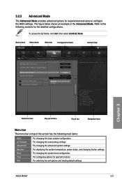
Refer to configure the BIOS settings. To access the EZ Mode, click Exit, then select ASUS EZ Mode. The figure below shows an example of the screen has the following sections for the detailed configurations. Back button Menu items Menu bar ... Version 2.00.1201. For changing the system boot configuration For configuring options for special functions For selecting the exit options and loading default settings Chapter 3 ASUS M5A97 3-3 Pop-up window Scroll bar Navigation keys Menu bar The menu bar on top of the Advanced Mode. Advanced Mode General help Exit Main Back...
Refer to configure the BIOS settings. To access the EZ Mode, click Exit, then select ASUS EZ Mode. The figure below shows an example of the screen has the following sections for the detailed configurations. Back button Menu items Menu bar ... Version 2.00.1201. For changing the system boot configuration For configuring options for special functions For selecting the exit options and loading default settings Chapter 3 ASUS M5A97 3-3 Pop-up window Scroll bar Navigation keys Menu bar The menu bar on top of the Advanced Mode. Advanced Mode General help Exit Main Back...


