

User Manual
Page 11
...® Socket AM3 multi-core processors with unique L3 cache and delivers better overclocking capabilities with less power consumption. ASUS M4A78LT-M PLUS 1-1 Chapter 1 Product introduction 1.1 Welcome! It features dual-channel DDR3 memory support and accelerates data transfer rate up...for the following items. Motherboard Cables Accessories Application DVD Documentation ASUS M4A78LT-M PLUS motherboard 2 x Serial ATA cables 1 x Ultra DMA 133/100/66 cable 1 x I/O shield ASUS motherboard Support DVD User Manual If any of ASUS quality motherboards! The motherboard delivers a host of new ...
...® Socket AM3 multi-core processors with unique L3 cache and delivers better overclocking capabilities with less power consumption. ASUS M4A78LT-M PLUS 1-1 Chapter 1 Product introduction 1.1 Welcome! It features dual-channel DDR3 memory support and accelerates data transfer rate up...for the following items. Motherboard Cables Accessories Application DVD Documentation ASUS M4A78LT-M PLUS motherboard 2 x Serial ATA cables 1 x Ultra DMA 133/100/66 cable 1 x I/O shield ASUS motherboard Support DVD User Manual If any of ASUS quality motherboards! The motherboard delivers a host of new ...

User Manual
Page 13
...Turbo Key boosts performances without interrupting ongoing work or games, simply through pressing the button. ASUS MyLogo2™ Turn your system. ASUS CrashFree BIOS 3 ASUS CrashFree BIOS 3 is an ASUS exclusive OS that provides you with quick access to the Internet and key applications before ...174; OS. • ASUS Express Gate supports installation on the system configuration. • ASUS Express Gate supports file uploading from SATA HDDs, ODDs and USB drives. ASUS EZ Flash 2 ASUS EZ Flash 2 allows you to update the BIOS from switching power supply (PSU). ASUS M4A78LT-M PLUS 1-3
...Turbo Key boosts performances without interrupting ongoing work or games, simply through pressing the button. ASUS MyLogo2™ Turn your system. ASUS CrashFree BIOS 3 ASUS CrashFree BIOS 3 is an ASUS exclusive OS that provides you with quick access to the Internet and key applications before ...174; OS. • ASUS Express Gate supports installation on the system configuration. • ASUS Express Gate supports file uploading from SATA HDDs, ODDs and USB drives. ASUS EZ Flash 2 ASUS EZ Flash 2 allows you to update the BIOS from switching power supply (PSU). ASUS M4A78LT-M PLUS 1-3
User Manual
Page 15
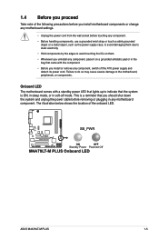
...; Unplug the power cord from the wall socket before removing or plugging in soft-off the ATX power supply and detach its power cord. SB_PWR M4A78LT-M PLUS ON OFF Standby Power Powered Off M4A78LT-M PLUS Onboard LED ASUS M4A78LT-M PLUS 1-5 1.4 Before you proceed Take note of the onboard LED.
...; Unplug the power cord from the wall socket before removing or plugging in soft-off the ATX power supply and detach its power cord. SB_PWR M4A78LT-M PLUS ON OFF Standby Power Powered Off M4A78LT-M PLUS Onboard LED ASUS M4A78LT-M PLUS 1-5 1.4 Before you proceed Take note of the onboard LED.
User Manual
Page 19
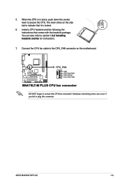
... lever clicks on the motherboard. You can occur if you fail to section 1.6.2 Installing heatsink and fan for instructions. 7. M4A78LT-M PLUS CPU_FAN GND CPU FAN PWR CPU FAN IN CPU FAN PWM M4A78LT-M PLUS CPU fan connector DO NOT forget to the CPU_FAN connector on the side tab to indicate that comes with the... heatsink package. Install a CPU heatsink and fan following the instructions that it is in place, push down the socket lever to secure the CPU. ASUS M4A78LT-M PLUS 1-9 Connect the CPU fan cable to connect the CPU fan connector! 5.
... lever clicks on the motherboard. You can occur if you fail to section 1.6.2 Installing heatsink and fan for instructions. 7. M4A78LT-M PLUS CPU_FAN GND CPU FAN PWR CPU FAN IN CPU FAN PWM M4A78LT-M PLUS CPU fan connector DO NOT forget to the CPU_FAN connector on the side tab to indicate that comes with the... heatsink package. Install a CPU heatsink and fan following the instructions that it is in place, push down the socket lever to secure the CPU. ASUS M4A78LT-M PLUS 1-9 Connect the CPU fan cable to connect the CPU fan connector! 5.

User Manual
Page 21
... heatsink assembly is in place. 4. 3. Align the other end of the DDR3 DIMM sockets: DIMM_A1 DIMM_B1 Channel Channel A Channel B Sockets DIMM_A1 DIMM_B1 M4A78LT-M PLUS M4A78LT-M PLUS 240-pin DDR3 DIMM sockets ASUS M4A78LT-M PLUS 1-11 Hardware monitoring errors can occur if you cannot snap the retention bracket in place. Ensure that the retention bracket is in place...
... heatsink assembly is in place. 4. 3. Align the other end of the DDR3 DIMM sockets: DIMM_A1 DIMM_B1 Channel Channel A Channel B Sockets DIMM_A1 DIMM_B1 M4A78LT-M PLUS M4A78LT-M PLUS 240-pin DDR3 DIMM sockets ASUS M4A78LT-M PLUS 1-11 Hardware monitoring errors can occur if you cannot snap the retention bracket in place. Ensure that the retention bracket is in place...
User Manual
Page 25
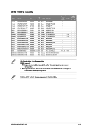
Size SS/ DS Brand Chip NO. Visit the ASUS website at www.asus.com for the latest QVL. ASUS M4A78LT-M PLUS 1-15 Crucial CT12864BA1067.8FF 1024MB SS Crucial CT12872BA1067.9FF 1024MB SS Crucial CT25664BA1067.16FF 2048MB DS Crucial CT25672BA1067.18FF 2048MB DS Elpida EBJ51UD8BAFA-AC-E 512MB ...
Size SS/ DS Brand Chip NO. Visit the ASUS website at www.asus.com for the latest QVL. ASUS M4A78LT-M PLUS 1-15 Crucial CT12864BA1067.8FF 1024MB SS Crucial CT12872BA1067.9FF 1024MB SS Crucial CT25664BA1067.16FF 2048MB DS Crucial CT25672BA1067.18FF 2048MB DS Elpida EBJ51UD8BAFA-AC-E 512MB ...

User Manual
Page 27
...). 3. Before installing the expansion card, read the documentation that you physical injury and damage motherboard components. 1.8.1 Installing an expansion card To install an expansion card: 1. ASUS M4A78LT-M PLUS 1-17 See Chapter 2 for later use . Failure to the card. 3. Secure the card to the chassis with the PCI Express specifications. Assign an IRQ to...
...). 3. Before installing the expansion card, read the documentation that you physical injury and damage motherboard components. 1.8.1 Installing an expansion card To install an expansion card: 1. ASUS M4A78LT-M PLUS 1-17 See Chapter 2 for later use . Failure to the card. 3. Secure the card to the chassis with the PCI Express specifications. Assign an IRQ to...

User Manual
Page 29
... (CPU stopped, DRAM refreshed, system running in reduced power mode). KBPWR 12 23 +5V +5VSB (Default) M4A78LT-M PLUS M4A78LT-M PLUS Keyboard Power Setting ASUS M4A78LT-M PLUS 1-19 USBPW1-4 12 23 +5V +5VSB (Default) USBPW5-10 M4A78LT-M PLUS 12 23 +5V +5VSB (Default) M4A78LT-M PLUS USB Device Wake Up 3. USB device wake-up (3-pin USBPW1-4, USBPW5-10) Set these jumpers to +5VSB...
... (CPU stopped, DRAM refreshed, system running in reduced power mode). KBPWR 12 23 +5V +5VSB (Default) M4A78LT-M PLUS M4A78LT-M PLUS Keyboard Power Setting ASUS M4A78LT-M PLUS 1-19 USBPW1-4 12 23 +5V +5VSB (Default) USBPW5-10 M4A78LT-M PLUS 12 23 +5V +5VSB (Default) M4A78LT-M PLUS USB Device Wake Up 3. USB device wake-up (3-pin USBPW1-4, USBPW5-10) Set these jumpers to +5VSB...
User Manual
Page 31
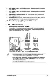
... AGND NC NC NC AAFP PIN 1 PIN 1 MIC2 MICPWR Line out_R NC Line out_L PORT1 L PORT1 R PORT2 R SENSE_SEND PORT2 L M4A78LT-M PLUS HD-audio-compliant Legacy AC'97 pin definition compliant definition M4A78LT-M PLUS Front panel audio connector • We recommend that supports either High Definition Audio or AC`97 audio standard. See section...panel audio I /O module is for a PS/2 keyboard. 1.10.2 Internal connectors 1. USB 2.0 ports 1 and 2. Front panel audio connector (10-1 pin AAFP) This connector is purchased separately. ASUS M4A78LT-M PLUS 1-21 DVI-D Out port.
... AGND NC NC NC AAFP PIN 1 PIN 1 MIC2 MICPWR Line out_R NC Line out_L PORT1 L PORT1 R PORT2 R SENSE_SEND PORT2 L M4A78LT-M PLUS HD-audio-compliant Legacy AC'97 pin definition compliant definition M4A78LT-M PLUS Front panel audio connector • We recommend that supports either High Definition Audio or AC`97 audio standard. See section...panel audio I /O module is for a PS/2 keyboard. 1.10.2 Internal connectors 1. USB 2.0 ports 1 and 2. Front panel audio connector (10-1 pin AAFP) This connector is purchased separately. ASUS M4A78LT-M PLUS 1-21 DVI-D Out port.

User Manual
Page 33
...on the IDE ribbon cable to PIN 1. If any device jumper is for Ultra DMA 133/100/66 IDE devices. 3. PRI_IDE PIN1 M4A78LT-M PLUS NOTE:Orient the red markings on each Ultra DMA 133/100/66 signal cable: blue, black, and gray. Master Slave Master Slave Cable...Select or Master Cable-Select Master Slave Mode of the following modes to match the covered hole on the Ultra DMA cable connector. M4A78LT-M PLUS IDE connector ASUS M4A78LT-M PLUS 1-23 Connect the blue connector to the motherboard's IDE connector, then select one of device(s) - This prevents incorrect insertion when ...
...on the IDE ribbon cable to PIN 1. If any device jumper is for Ultra DMA 133/100/66 IDE devices. 3. PRI_IDE PIN1 M4A78LT-M PLUS NOTE:Orient the red markings on each Ultra DMA 133/100/66 signal cable: blue, black, and gray. Master Slave Master Slave Cable...Select or Master Cable-Select Master Slave Mode of the following modes to match the covered hole on the Ultra DMA cable connector. M4A78LT-M PLUS IDE connector ASUS M4A78LT-M PLUS 1-23 Connect the blue connector to the motherboard's IDE connector, then select one of device(s) - This prevents incorrect insertion when ...
User Manual
Page 35
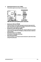
Connect the HDD Activity LED cable to this connector. PWR LED PWR BTN F_PANEL PIN 1 M4A78LT-M PLUS HD_LED RESET M4A78LT-M PLUS System panel connector • System power LED (2-pin PWRLED) This 2-pin connector is for the HDD Activity LED. PLED+ PLEDPWR GND IDE_LED+ IDE_LED-... connector supports several chassis-mounted functions. The system power LED lights up or flashes when data is read from or written to this connector. ASUS M4A78LT-M PLUS 1-25 Connect the chassis power LED cable to the HDD. • Power/Soft-off button (2-pin PWRBTN) This connector is for the system...
Connect the HDD Activity LED cable to this connector. PWR LED PWR BTN F_PANEL PIN 1 M4A78LT-M PLUS HD_LED RESET M4A78LT-M PLUS System panel connector • System power LED (2-pin PWRLED) This 2-pin connector is for the HDD Activity LED. PLED+ PLEDPWR GND IDE_LED+ IDE_LED-... connector supports several chassis-mounted functions. The system power LED lights up or flashes when data is read from or written to this connector. ASUS M4A78LT-M PLUS 1-25 Connect the chassis power LED cable to the HDD. • Power/Soft-off button (2-pin PWRBTN) This connector is for the system...

User Manual
Page 37
... connector (4-pin SPEAKER) This 4-pin connector is for the chassis-mounted system warning speaker. SPEAKER +5V GND GND Speaker Out M4A78LT-M PLUS PIN 1 M4A78LT-M PLUS Speaker Out Connector ASUS M4A78LT-M PLUS 1-27 M4A78LT-M PLUS SPDIF_OUT GND SPDIFOUT +5V M4A78LT-M PLUS Digital audio connector Ensure that the audio device of Sound playback is purchased separately. 9. Digital audio connector (4-1 pin SPDIF_OUT) This connector...
... connector (4-pin SPEAKER) This 4-pin connector is for the chassis-mounted system warning speaker. SPEAKER +5V GND GND Speaker Out M4A78LT-M PLUS PIN 1 M4A78LT-M PLUS Speaker Out Connector ASUS M4A78LT-M PLUS 1-27 M4A78LT-M PLUS SPDIF_OUT GND SPDIFOUT +5V M4A78LT-M PLUS Digital audio connector Ensure that the audio device of Sound playback is purchased separately. 9. Digital audio connector (4-1 pin SPDIF_OUT) This connector...

User Manual
Page 39
...174; XP / Vista / 7 Operating Systems (OS). Click Drivers, Utilities, Make Disk, Manual, and Contact tabs to change at www.asus.com for better compatibility and system stability. 1.11.2 Support DVD information The Support DVD that comes with the motherboard package contains the drivers, ...Specials screen which contains the unique feature of the Support DVD to your hardware. • Motherboard settings and hardware options vary. ASUS M4A78LT-M PLUS 1-29 Click an icon to display Support DVD/ motherboard information Click an item to avail all motherboard features. The contents of ...
...174; XP / Vista / 7 Operating Systems (OS). Click Drivers, Utilities, Make Disk, Manual, and Contact tabs to change at www.asus.com for better compatibility and system stability. 1.11.2 Support DVD information The Support DVD that comes with the motherboard package contains the drivers, ...Specials screen which contains the unique feature of the Support DVD to your hardware. • Motherboard settings and hardware options vary. ASUS M4A78LT-M PLUS 1-29 Click an icon to display Support DVD/ motherboard information Click an item to avail all motherboard features. The contents of ...

User Manual
Page 41
..., select the BIOS version that you to restore the BIOS in the future. Installing ASUS Update To install ASUS Update: 1. c. ASUS M4A78LT-M PLUS 2-1 The Drivers menu appears. 2. Follow the onscreen instructions to download then click Next. Click the Utilities tab, then click ASUS Update. 3. Quit all its features. Always update the utility to avail all Windows...
..., select the BIOS version that you to restore the BIOS in the future. Installing ASUS Update To install ASUS Update: 1. c. ASUS M4A78LT-M PLUS 2-1 The Drivers menu appears. 2. Follow the onscreen instructions to download then click Next. Click the Utilities tab, then click ASUS Update. 3. Quit all its features. Always update the utility to avail all Windows...

User Manual
Page 43
... reset the system while updating the BIOS! 2.1.3 ASUS CrashFree BIOS utility The ASUS CrashFree BIOS is found, the utility reads it fails or gets corrupted during the updating process. You can cause system boot failure! ASUS M4A78LT-M PLUS 2-3 When the BIOS file is an auto recovery... tool that ASUS CrashFree BIOS supports vary with motherboard models. Turn off the system after the utility completes the...
... reset the system while updating the BIOS! 2.1.3 ASUS CrashFree BIOS utility The ASUS CrashFree BIOS is found, the utility reads it fails or gets corrupted during the updating process. You can cause system boot failure! ASUS M4A78LT-M PLUS 2-3 When the BIOS file is an auto recovery... tool that ASUS CrashFree BIOS supports vary with motherboard models. Turn off the system after the utility completes the...
User Manual
Page 45
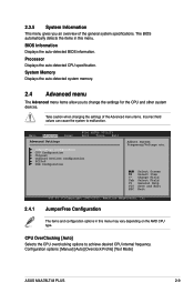
ASUS M4A78LT-M PLUS 2-5 Some of the navigation keys differ from one screen to select items in the menu and change the settings. To select an item on the ...
ASUS M4A78LT-M PLUS 2-5 Some of the navigation keys differ from one screen to select items in the menu and change the settings. To select an item on the ...

User Manual
Page 47
... item to set the system date. 2.3.3 Primary IDE Master/Slave, SATA 1/2/3/4/5/6 While entering Setup, the BIOS automatically detects the presence of the basic system information. ASUS M4A78LT-M PLUS 2-7 There is a separate submenu for information on the menu screen items and how to navigate through them. 2.3.1 System Time [xx:xx:xx] Allows you to...
... item to set the system date. 2.3.3 Primary IDE Master/Slave, SATA 1/2/3/4/5/6 While entering Setup, the BIOS automatically detects the presence of the basic system information. ASUS M4A78LT-M PLUS 2-7 There is a separate submenu for information on the menu screen items and how to navigate through them. 2.3.1 System Time [xx:xx:xx] Allows you to...
User Manual
Page 49
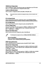
... menu may vary depending on the AMD CPU type. BIOS Information Displays the auto-detected BIOS information. Configuration options: [Manual] [Auto] [Overclock Profile] [Test Mode] ASUS M4A78LT-M PLUS 2-9 The BIOS automatically detects the items in this menu. CPU OverClocking [Auto] Selects the CPU overclocking options to achieve desired CPU internal frequency. Processor Displays...
... menu may vary depending on the AMD CPU type. BIOS Information Displays the auto-detected BIOS information. Configuration options: [Manual] [Auto] [Overclock Profile] [Test Mode] ASUS M4A78LT-M PLUS 2-9 The BIOS automatically detects the items in this menu. CPU OverClocking [Auto] Selects the CPU overclocking options to achieve desired CPU internal frequency. Processor Displays...
User Manual
Page 51
... the memory over voltage. Use the / keys to adjust the ratio. Use the / keys to adjust the value. Configuration options: [Auto] [Max. = 1.61000V] [Min. = 1.10000V] ASUS M4A78LT-M PLUS 2-11 Configuration options: [Auto] [200MHz] [400MHz] [600MHz] [800MHZ] [1000MHz] [1200MHz] [1400MHz] [1600MHz] [1800MHz] [2000MHz] HT Link Width [Auto] Sets the HyperTransport link width. Configuration options...
... the memory over voltage. Use the / keys to adjust the ratio. Use the / keys to adjust the value. Configuration options: [Auto] [Max. = 1.61000V] [Min. = 1.10000V] ASUS M4A78LT-M PLUS 2-11 Configuration options: [Auto] [200MHz] [400MHz] [600MHz] [800MHZ] [1000MHz] [1200MHz] [1400MHz] [1600MHz] [1800MHz] [2000MHz] HT Link Width [Auto] Sets the HyperTransport link width. Configuration options...

User Manual
Page 53
...] Internal Graphics Primary Video Controller [GFX0-GPP-IGFX-PCI] Selects the primary display adapter. Frame Buffer Location [Above 4G] Configuration options: [Below 4G] [Above 4G] ASUS M4A78LT-M PLUS 2-13 Configuration options: [GFX0-GPP-IGFX-PCI] [GPPGFX0-IGFX-PCI] [PCI-GFX0-GPP-IGFX] [IGFX-GFX0-GPP-PCI] GFX0:primary video controller on a PCIe x16...
...] Internal Graphics Primary Video Controller [GFX0-GPP-IGFX-PCI] Selects the primary display adapter. Frame Buffer Location [Above 4G] Configuration options: [Below 4G] [Above 4G] ASUS M4A78LT-M PLUS 2-13 Configuration options: [GFX0-GPP-IGFX-PCI] [GPPGFX0-IGFX-PCI] [PCI-GFX0-GPP-IGFX] [IGFX-GFX0-GPP-PCI] GFX0:primary video controller on a PCIe x16...

