
User Manual
Page 8
...Product introduction This chapter describes the features of the motherboard and the new technology it supports. • Chapter 2: BIOS setup This chapter tells how to the ASUS contact information. 2. These documents are also provided. • Chapter 3: Software support This chapter describes the contents... may include optional documentation, such as warranty flyers, that comes with the motherboard package. Refer to change system settings through the BIOS Setup menus. viii About this guide is organized This guide contains the following sources for additional information and for ...
...Product introduction This chapter describes the features of the motherboard and the new technology it supports. • Chapter 2: BIOS setup This chapter tells how to the ASUS contact information. 2. These documents are also provided. • Chapter 3: Software support This chapter describes the contents... may include optional documentation, such as warranty flyers, that comes with the motherboard package. Refer to change system settings through the BIOS Setup menus. viii About this guide is organized This guide contains the following sources for additional information and for ...
User Manual
Page 30
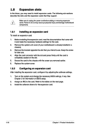
...slot that they support. Turn on BIOS setup. 2. Refer to unplug the power cord before adding or removing expansion cards. Make sure to the tables on the slot. 5. Keep the screw for information on the system and change the necessary BIOS settings, if any. Align the card connector... with it by adjusting the software settings. 1. See Chapter 2 for later use . Failure to install expansion cards. Remove the system unit cover ...
...slot that they support. Turn on BIOS setup. 2. Refer to unplug the power cord before adding or removing expansion cards. Make sure to the tables on the slot. 5. Keep the screw for information on the system and change the necessary BIOS settings, if any. Align the card connector... with it by adjusting the software settings. 1. See Chapter 2 for later use . Failure to install expansion cards. Remove the system unit cover ...
User Manual
Page 33
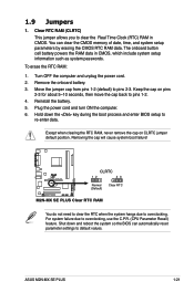
...BIOS can clear the CMOS memory of date, time, and system setup parameters by erasing the CMOS RTC RAM data. You can automatically reset parameter settings to default values. Keep the cap on CLRTC jumper default position. R M2N-MX SE PLUS CLRTC 12 23 Normal (Default) Clear RTC M2N-MX SE PLUS... Clear RTC RAM You do not need to clear the RTC when the system hangs due to pins 2-3. ASUS M2N-MX SE PLUS 1-21 The...
...BIOS can clear the CMOS memory of date, time, and system setup parameters by erasing the CMOS RTC RAM data. You can automatically reset parameter settings to default values. Keep the cap on CLRTC jumper default position. R M2N-MX SE PLUS CLRTC 12 23 Normal (Default) Clear RTC M2N-MX SE PLUS... Clear RTC RAM You do not need to clear the RTC when the system hangs due to pins 2-3. ASUS M2N-MX SE PLUS 1-21 The...
User Manual
Page 38
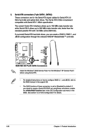
... RSATA_TXP2 RSATA_TXN2 GND RSATA_RXP2 RSATA_RXN2 GND R M2N-MX SE PLUS SATA1 GND RSATA_TXP1 RSATA_TXN1 GND RSATA_RXP1 RSATA_RXN1 GND M2N-MX SE PLUS SATA Connectors Install the Windows® 2000.... 3. If you install Serial ATA hard disk drives, you intend to create a Serial ATA RAID set using Serial ATA. • For detailed instructions on how to configure RAID 0, 1, and JBOD, refer... these connectors, enable the nVidia RAID Function item in the IDE Configuration sub-menu in the BIOS. Serial ATA connectors (7-pin SATA1, SATA2) These connectors are for the Serial ATA signal cables...
... RSATA_TXP2 RSATA_TXN2 GND RSATA_RXP2 RSATA_RXN2 GND R M2N-MX SE PLUS SATA1 GND RSATA_TXP1 RSATA_TXN1 GND RSATA_RXP1 RSATA_RXN1 GND M2N-MX SE PLUS SATA Connectors Install the Windows® 2000.... 3. If you install Serial ATA hard disk drives, you intend to create a Serial ATA RAID set using Serial ATA. • For detailed instructions on how to configure RAID 0, 1, and JBOD, refer... these connectors, enable the nVidia RAID Function item in the IDE Configuration sub-menu in the BIOS. Serial ATA connectors (7-pin SATA1, SATA2) These connectors are for the Serial ATA signal cables...
User Manual
Page 41
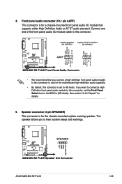
...M2N-MX SE PLUS SPEAKER 1 +5V GND GND Speaker Out M2N-MX SE PLUS Speaker Out Connector ASUS M2N-MX SE PLUS 1-29 Azalia-compliant Legacy AC'97-compliant pin definition pin definition AGND PRESENSE# MIC2_JD HP_HD AGND NC NC NC R M2N-MX SE PLUS AAFP MIC2_L MIC2_R Line out_R NC Line out_L MIC2_L MIC2_R HP_R Jack_Sense HP_L M2N-MX SE PLUS... front panel audio I /O module cable to this connector, set to hear system beeps and warnings. Speaker connector (4-pin SPEAKER) This connector is set the Front Panel Select item in the BIOS to avail of the front panel audio I /O module that...
...M2N-MX SE PLUS SPEAKER 1 +5V GND GND Speaker Out M2N-MX SE PLUS Speaker Out Connector ASUS M2N-MX SE PLUS 1-29 Azalia-compliant Legacy AC'97-compliant pin definition pin definition AGND PRESENSE# MIC2_JD HP_HD AGND NC NC NC R M2N-MX SE PLUS AAFP MIC2_L MIC2_R Line out_R NC Line out_L MIC2_L MIC2_R HP_R Jack_Sense HP_L M2N-MX SE PLUS... front panel audio I /O module cable to this connector, set to hear system beeps and warnings. Speaker connector (4-pin SPEAKER) This connector is set the Front Panel Select item in the BIOS to avail of the front panel audio I /O module that...
User Manual
Page 43
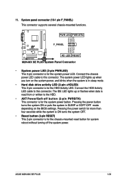
...to the HDD. • AXT Power/Soft-off the system power. PWR LED PWR BTN PLED+ PLEDPWR GND R M2N-MX SE PLUS F_PANEL IDELED+ IDELED- Ground Reset HD LED RESET M2N-MX SE PLUS System Panel Connector • System power LED (2-pin PWRLED) This 2-pin connector is for the chassis-mounted reset ...lights up when you turn on the BIOS settings. Pressing the power button turns the system ON or puts the system in sleep mode. • Hard disk drive activity LED (2-pin +HDLED) This 2-pin connector is for the system power button. ASUS M2N-MX SE PLUS 1-31 The system power LED lights...
...to the HDD. • AXT Power/Soft-off the system power. PWR LED PWR BTN PLED+ PLEDPWR GND R M2N-MX SE PLUS F_PANEL IDELED+ IDELED- Ground Reset HD LED RESET M2N-MX SE PLUS System Panel Connector • System power LED (2-pin PWRLED) This 2-pin connector is for the chassis-mounted reset ...lights up when you turn on the BIOS settings. Pressing the power button turns the system ON or puts the system in sleep mode. • Hard disk drive activity LED (2-pin +HDLED) This 2-pin connector is for the system power button. ASUS M2N-MX SE PLUS 1-31 The system power LED lights...
User Manual
Page 45
This chapter tells how to change the system settings through the BIOS Setup menus. Detailed descriptions of the BIOS parameters are also provided. 2 BIOS setup
This chapter tells how to change the system settings through the BIOS Setup menus. Detailed descriptions of the BIOS parameters are also provided. 2 BIOS setup
User Manual
Page 46
...ASUS Update: Updates the BIOS in the future. Copy the original motherboard BIOS using a bootable floppy disk, or the motherboard support CD when the BIOS file fails or gets corrupted. 4. Insert a 1.44MB floppy disk into the drive. b. Windows® XP environment a. c. Windows® 2000 environment To create a set... of the following utilities allow you need to restore the BIOS in Windows® environment. Click Start, then select Run. From the Open field, type D:\bootdisk\...
...ASUS Update: Updates the BIOS in the future. Copy the original motherboard BIOS using a bootable floppy disk, or the motherboard support CD when the BIOS file fails or gets corrupted. 4. Insert a 1.44MB floppy disk into the drive. b. Windows® XP environment a. c. Windows® 2000 environment To create a set... of the following utilities allow you need to restore the BIOS in Windows® environment. Click Start, then select Run. From the Open field, type D:\bootdisk\...
User Manual
Page 55
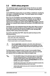
...Test (POST) to your selections from the operating system. Being a menu-driven program, it as easy to use as possible. ASUS M2N-MX SE PLUS 2-11 When you start up the computer, the system provides you wish to enter Setup after changing any of the following procedures:... password feature or change the configuration of your system using the navigation keys. • The default BIOS settings for this motherboard apply for this program. 2.2 BIOS setup program This motherboard supports a programmable firmware chip that the computer can recognize these changes and record...
...Test (POST) to your selections from the operating system. Being a menu-driven program, it as easy to use as possible. ASUS M2N-MX SE PLUS 2-11 When you start up the computer, the system provides you wish to enter Setup after changing any of the following procedures:... password feature or change the configuration of your system using the navigation keys. • The default BIOS settings for this motherboard apply for this program. 2.2 BIOS setup program This motherboard supports a programmable firmware chip that the computer can recognize these changes and record...

User Manual
Page 56
... main items: Main Advanced Power Boot Exit For changing the basic system configuration For changing the advanced system settings For changing the advanced power management (APM) configuration For changing the system boot configuration For selecting the exit options and loading...desired item is highlighted. 2.2.3 Navigation keys At the bottom right corner of the navigation keys differ from one screen to configure system time. 2.2.1 BIOS menu screen Menu items Menu bar Configuration fields System Time System Date Legacy Diskette A Exit [17: 44 : 20] [Tue01/15/2002] ...
... main items: Main Advanced Power Boot Exit For changing the basic system configuration For changing the advanced system settings For changing the advanced power management (APM) configuration For changing the system boot configuration For selecting the exit options and loading...desired item is highlighted. 2.2.3 Navigation keys At the bottom right corner of the navigation keys differ from one screen to configure system time. 2.2.1 BIOS menu screen Menu items Menu bar Configuration fields System Time System Date Legacy Diskette A Exit [17: 44 : 20] [Tue01/15/2002] ...

User Manual
Page 58
... [1.2M , 5.25 in.] [720K , 3.5 in.] [1.44M, 3.5 in.] [2.88M, 3.5 in.] 2-14 Chapter 2: BIOS setup 2.3 Main menu When you enter the BIOS Setup program, the Main menu screen appears, giving you to set the system date. 2.3.3 Legacy Diskette A [1.44M, 3.5 in ] :[Not Detected] :[Not Detected] :[Not Detected] :[Not ...Detected] Use [ENTER], [TAB] or [SHIFT-TAB] to select a field. Refer to section "2.2.1 BIOS menu screen" for information on the...
... [1.2M , 5.25 in.] [720K , 3.5 in.] [1.44M, 3.5 in.] [2.88M, 3.5 in.] 2-14 Chapter 2: BIOS setup 2.3 Main menu When you enter the BIOS Setup program, the Main menu screen appears, giving you to set the system date. 2.3.3 Legacy Diskette A [1.44M, 3.5 in ] :[Not Detected] :[Not Detected] :[Not Detected] :[Not ...Detected] Use [ENTER], [TAB] or [SHIFT-TAB] to select a field. Refer to section "2.2.1 BIOS menu screen" for information on the...
User Manual
Page 59
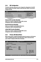
... IDE devices. ASUS M2N-MX SE PLUS 2-15 Onboard IDE Controller [Enabled] Allows you to disable or set or change the configurations for each IDE device. Configuration options: [Disabled] [Enabled] nVidia RAID Function [Disabled] Allows you to set the Serial-ATA devices. Configuration options: [Enabled] [Disabled] 2.3.5 Primary IDE Master/Slave While entering Setup, the BIOS automatically detects the...
... IDE devices. ASUS M2N-MX SE PLUS 2-15 Onboard IDE Controller [Enabled] Allows you to disable or set or change the configurations for each IDE device. Configuration options: [Disabled] [Enabled] nVidia RAID Function [Disabled] Allows you to set the Serial-ATA devices. Configuration options: [Enabled] [Disabled] 2.3.5 Primary IDE Master/Slave While entering Setup, the BIOS automatically detects the...
User Manual
Page 60
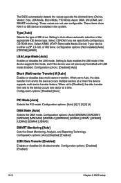
The BIOS automatically detects the values opposite the dimmed items (Device, Vendor, Size...: [Disabled] [Auto] Block (Multi-sector Transfer) M [Auto] Enables or disables data multi-sectors transfers. When set to [Disabled], the data transfer from and to Auto allows automatic selection of IDE drive. Type [Auto] Selects the... [SWDMA1] [SWDMA2] [MWDMA0] [MWDMA1] [MWDMA2] [UDMA0] [UDMA1] [UDMA2] [UDMA3] [UDMA4] [UDMA5] SMART Monitoring [Auto] Sets the Smart Monitoring, Analysis, and Reporting Technology. Select CDROM if you are not user-configurable. These items show N/A if no IDE device is ...
The BIOS automatically detects the values opposite the dimmed items (Device, Vendor, Size...: [Disabled] [Auto] Block (Multi-sector Transfer) M [Auto] Enables or disables data multi-sectors transfers. When set to [Disabled], the data transfer from and to Auto allows automatic selection of IDE drive. Type [Auto] Selects the... [SWDMA1] [SWDMA2] [MWDMA0] [MWDMA1] [MWDMA2] [UDMA0] [UDMA1] [UDMA2] [UDMA3] [UDMA4] [UDMA5] SMART Monitoring [Auto] Sets the Smart Monitoring, Analysis, and Reporting Technology. Select CDROM if you are not user-configurable. These items show N/A if no IDE device is ...
User Manual
Page 61
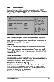
... the device supports it and the device is a separate sub-menu for each SATA device. Setting to display the SATA device information. Configuration options: [Disabled] [Auto] ASUS M2N-MX SE PLUS 2-17 These values are specifically configuring a CD-ROM drive. Configuration options: [Disabled] [Auto...[Enabled] Disabled: Disables LBA Mode. When set to [Disabled], the data transfer from and to Auto allows automatic selection of the appropriate IDE device type. Select CDROM if you are not user-configurable. The BIOS automatically detects the values opposite the dimmed items...
... the device supports it and the device is a separate sub-menu for each SATA device. Setting to display the SATA device information. Configuration options: [Disabled] [Auto] ASUS M2N-MX SE PLUS 2-17 These values are specifically configuring a CD-ROM drive. Configuration options: [Disabled] [Auto...[Enabled] Disabled: Disables LBA Mode. When set to [Disabled], the data transfer from and to Auto allows automatic selection of the appropriate IDE device type. Select CDROM if you are not user-configurable. The BIOS automatically detects the values opposite the dimmed items...
User Manual
Page 62
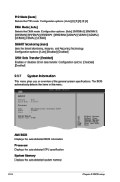
...[Auto] [SWDMA0] [SWDMA1] [SWDMA2] [MWDMA0] [MWDMA1] [MWDMA2] [UDMA0] [UDMA1] [UDMA2] [UDMA3] [UDMA4] [UDMA5] SMART Monitoring [Auto] Sets the Smart Monitoring, Analysis, and Reporting Technology. Configuration options: [Disabled] [Enabled] 2.3.7 System Information This menu gives you an overview of the general system specifications. AMIBIOS... Sempron(tm) Processor 3200+ : 1800MHz : 1 System Memory Usable Size: 384MB AMI BIOS Displays the auto-detected BIOS information Processor Displays the auto-detected CPU specification System Memory Displays the auto-detected system memory 2-18 Chapter...
...[Auto] [SWDMA0] [SWDMA1] [SWDMA2] [MWDMA0] [MWDMA1] [MWDMA2] [UDMA0] [UDMA1] [UDMA2] [UDMA3] [UDMA4] [UDMA5] SMART Monitoring [Auto] Sets the Smart Monitoring, Analysis, and Reporting Technology. Configuration options: [Disabled] [Enabled] 2.3.7 System Information This menu gives you an overview of the general system specifications. AMIBIOS... Sempron(tm) Processor 3200+ : 1800MHz : 1 System Memory Usable Size: 384MB AMI BIOS Displays the auto-detected BIOS information Processor Displays the auto-detected CPU specification System Memory Displays the auto-detected system memory 2-18 Chapter...
User Manual
Page 66
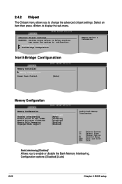
Advanced Chipset Settings WARNING: Setting wrong values in below sections may cause the system to display the sub-menu. NorthBridge Configuration Southbridge Configuration NorthBridge Configuration Memory ...] [Auto] [Disabled] [Disabled] [Enabled] [Enabled] Enable Bank Memory Interleaving Bank Interleaving [Disabled] Allows you to change the advanced chipset settings. Select an item then press to malfunction. Configuration options: [Disabled] [Auto] 2-22 Chapter 2: BIOS setup 2.4.2 Chipset The Chipset menu allows you to enable or disable the Bank Memory Interleaving.
Advanced Chipset Settings WARNING: Setting wrong values in below sections may cause the system to display the sub-menu. NorthBridge Configuration Southbridge Configuration NorthBridge Configuration Memory ...] [Auto] [Disabled] [Disabled] [Enabled] [Enabled] Enable Bank Memory Interleaving Bank Interleaving [Disabled] Allows you to change the advanced chipset settings. Select an item then press to malfunction. Configuration options: [Disabled] [Auto] 2-22 Chapter 2: BIOS setup 2.4.2 Chipset The Chipset menu allows you to enable or disable the Bank Memory Interleaving.
User Manual
Page 68
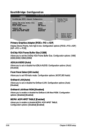
...Size. Configuration options: [AC97] [HD Audio] OnBoard LAN [Auto] Allows you to set or disable the AZALIA AUDIO. Configuration options: [16M] [32M] [64M] [128M] [256M] AZALIA AUDIO [Auto] Allows you to set or disable the OnBoard LAN. SouthBridge Configuration SouthBridge MCP61 chipset Configuration Primary Graphics Adapter [PCIE...MCP61 ACPI HPET TABLE [Enabled] Allows you to enable or disable the OnBoard LAN Boot ROM. Configuration options: [Disabled] [Enabled] 2-24 Chapter 2: BIOS setup Configuration options: [Auto] [Disabled] OnBoard LAN Boot ROM [Disabled] Allows you to low.
...Size. Configuration options: [AC97] [HD Audio] OnBoard LAN [Auto] Allows you to set or disable the AZALIA AUDIO. Configuration options: [16M] [32M] [64M] [128M] [256M] AZALIA AUDIO [Auto] Allows you to set or disable the OnBoard LAN. SouthBridge Configuration SouthBridge MCP61 chipset Configuration Primary Graphics Adapter [PCIE...MCP61 ACPI HPET TABLE [Enabled] Allows you to enable or disable the OnBoard LAN Boot ROM. Configuration options: [Disabled] [Enabled] 2-24 Chapter 2: BIOS setup Configuration options: [Auto] [Disabled] OnBoard LAN Boot ROM [Disabled] Allows you to low.

User Manual
Page 69
...DMA0] [DMA1] [DMA3] Parallel Port IRQ [IRQ7] Allows you to select the Parallel Port base addresses. Configuration options: [IRQ5] [IRQ7] ASUS M2N-MX SE PLUS 2-25 Configuration options: [Disabled] [3F8/IRQ4][2F8/IRQ3] [3E8/IRQ4] [2E8/IRQ3] Parallel Port Address [378] Allows you to select the... [378] Parallel Port Mode [Normal] Parallel Port IRQ [IRQ7] Allows BIOS to [EPP] or [EPP+ECP]. This item allows you to set to select the Serial Port1 base address. This item allows you to set to Select Serial Port1 Base Addresses. Configuration options: [1.9] [1.7] ECP Mode ...
...DMA0] [DMA1] [DMA3] Parallel Port IRQ [IRQ7] Allows you to select the Parallel Port base addresses. Configuration options: [IRQ5] [IRQ7] ASUS M2N-MX SE PLUS 2-25 Configuration options: [Disabled] [3F8/IRQ4][2F8/IRQ3] [3E8/IRQ4] [2E8/IRQ3] Parallel Port Address [378] Allows you to select the... [378] Parallel Port Mode [Normal] Parallel Port IRQ [IRQ7] Allows BIOS to [EPP] or [EPP+ECP]. This item allows you to set to select the Serial Port1 base address. This item allows you to set to Select Serial Port1 Base Addresses. Configuration options: [1.9] [1.7] ECP Mode ...

User Manual
Page 70
... and DMA channel resources for either PCI/PnP or legacy ISA devices, and setting the memory size block for boot if your system has a Plug and Play operating system. When set to [Yes], BIOS assigns an IRQ to PCI VGA card if the card requests for boot. Configuration options: [32] [64] [96] [... palete snooping feature informs the PCI devices that the latter can cause the system to change the advanced settings for the PCI device latency timer register. Plug and Play O/S [No] When set to [No], BIOS does not assign an IRQ to the PCI VGA card even if requested. YES: lets the operating ...
... and DMA channel resources for either PCI/PnP or legacy ISA devices, and setting the memory size block for boot if your system has a Plug and Play operating system. When set to [Yes], BIOS assigns an IRQ to PCI VGA card if the card requests for boot. Configuration options: [32] [64] [96] [... palete snooping feature informs the PCI devices that the latter can cause the system to change the advanced settings for the PCI device latency timer register. Plug and Play O/S [No] When set to [No], BIOS does not assign an IRQ to the PCI VGA card even if requested. YES: lets the operating ...

User Manual
Page 77
... power-on EsSeClf teExsitst (POST) while booting to decrease the time needed to boot the system. Configuration options: [Disabled] [Enabled] ASUS M2N-MX SE PLUS 2-33 Configuration options: [Disabled] [Enabled] Set this item allows the BIOS to skip some power on state for the F1 key to run Setup" during POST. Configuration options: [Disabled] [Enabled] Hit 'DEL...
... power-on EsSeClf teExsitst (POST) while booting to decrease the time needed to boot the system. Configuration options: [Disabled] [Enabled] ASUS M2N-MX SE PLUS 2-33 Configuration options: [Disabled] [Enabled] Set this item allows the BIOS to skip some power on state for the F1 key to run Setup" during POST. Configuration options: [Disabled] [Enabled] Hit 'DEL...


