H61M-E User's Manual
Page 11
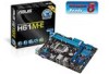
... Super I/O ALC PCIEX1_2 887 USBPW5-10 SB_PWR USB56 USB78 AAFP USB910 Intel® H61 CLRTC SPEAKER F_PANEL 64Mb BIOS SATA3G_3 SATA3G_1 SATA3G_4 SATA3G_2 ASUS H61M-E motherboard User Guide 2 x Serial ATA 3.0 Gb/s cables 1 x I/O Shield User Guide Support DVD • If any of the above items is damaged or missing, contact your ...
... Super I/O ALC PCIEX1_2 887 USBPW5-10 SB_PWR USB56 USB78 AAFP USB910 Intel® H61 CLRTC SPEAKER F_PANEL 64Mb BIOS SATA3G_3 SATA3G_1 SATA3G_4 SATA3G_2 ASUS H61M-E motherboard User Guide 2 x Serial ATA 3.0 Gb/s cables 1 x I/O Shield User Guide Support DVD • If any of the above items is damaged or missing, contact your ...
H61M-E User's Manual
Page 13
ASUS H61M-E 1-1 Product introduction 1 1.1 Special features 1.1.1 Product highlights LGA1155 socket for a x16 link reaches a maximum of 32Gb/s, double the 16 Gb/s of PCIe 2.0 (in x16 mode). Intel&#...
ASUS H61M-E 1-1 Product introduction 1 1.1 Special features 1.1.1 Product highlights LGA1155 socket for a x16 link reaches a maximum of 32Gb/s, double the 16 Gb/s of PCIe 2.0 (in x16 mode). Intel&#...
H61M-E User's Manual
Page 15
...the CPU fan and chassis fan speeds according to restore a corrupted BIOS file using a bootable floppy disk or an OS-based utility. ASUS EZ Flash 2 ASUS EZ Flash 2 is European Union´s Energy-related Products (ErP) ready, and ErP requires products to meet certain energy efficiency requirements in... of the product and thus mitigate environmental impacts. This all-in regards to launch and operate these utilities simultaneously. ASUS H61M-E 1-3 ASUS MyLogo2™ Turn your system. It allows you to personalize your favorite photos into 256-color boot logos to supervise fan...
...the CPU fan and chassis fan speeds according to restore a corrupted BIOS file using a bootable floppy disk or an OS-based utility. ASUS EZ Flash 2 ASUS EZ Flash 2 is European Union´s Energy-related Products (ErP) ready, and ErP requires products to meet certain energy efficiency requirements in... of the product and thus mitigate environmental impacts. This all-in regards to launch and operate these utilities simultaneously. ASUS H61M-E 1-3 ASUS MyLogo2™ Turn your system. It allows you to personalize your favorite photos into 256-color boot logos to supervise fan...
H61M-E User's Manual
Page 17
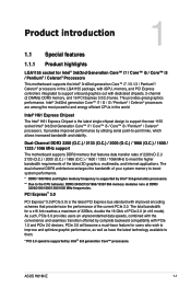
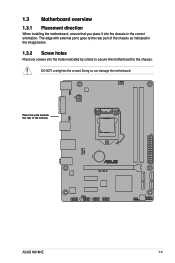
The edge with external ports goes to the chassis. Doing so can damage the motherboard. Place this side towards the rear of the chassis as indicated in the correct orientation. DO NOT overtighten the screws! 1.3 Motherboard overview 1.3.1 Placement direction When installing the motherboard, ensure that you place it into the chassis in the image below. 1.3.2 Screw holes Place six screws into the holes indicated by circles to secure the motherboard to the rear part of the chassis H61M-E ASUS H61M-E 1-5
The edge with external ports goes to the chassis. Doing so can damage the motherboard. Place this side towards the rear of the chassis as indicated in the correct orientation. DO NOT overtighten the screws! 1.3 Motherboard overview 1.3.1 Placement direction When installing the motherboard, ensure that you place it into the chassis in the image below. 1.3.2 Screw holes Place six screws into the holes indicated by circles to secure the motherboard to the rear part of the chassis H61M-E ASUS H61M-E 1-5
H61M-E User's Manual
Page 19
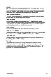
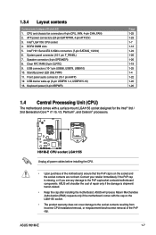
... mount LGA1155 socket designed for the Intel® 3rd / 2nd Generation Core™ i7 / i5 / i3, Pentium®, and Celeron® processors. ASUS H61M-E 1-7 USB connectors (10-1 pin USB56, USB78, USB910) 10. Front panel audio connector (10-1 pin AAFP) 12. DDR3 DIMM slots 5. System panel... connectors (24-pin EATXPWR, 4-pin ATX12V) 3. Speaker connector (4-pin SPEAKER) 8. USB device wake-up (3-pin USBPW 1-4, USBPW 5-10) 13. H61M-E H61M-E CPU socket LGA1155 Unplug all power cables before installing the CPU. • Upon purchase of repair only if the damage is missing, or if you...
... mount LGA1155 socket designed for the Intel® 3rd / 2nd Generation Core™ i7 / i5 / i3, Pentium®, and Celeron® processors. ASUS H61M-E 1-7 USB connectors (10-1 pin USB56, USB78, USB910) 10. Front panel audio connector (10-1 pin AAFP) 12. DDR3 DIMM slots 5. System panel... connectors (24-pin EATXPWR, 4-pin ATX12V) 3. Speaker connector (4-pin SPEAKER) 8. USB device wake-up (3-pin USBPW 1-4, USBPW 5-10) 13. H61M-E H61M-E CPU socket LGA1155 Unplug all power cables before installing the CPU. • Upon purchase of repair only if the damage is missing, or if you...
H61M-E User's Manual
Page 23
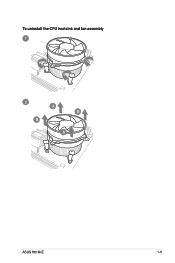
To uninstall the CPU heatsink and fan assembly 1 2 B A B A ASUS H61M-E 1-11
To uninstall the CPU heatsink and fan assembly 1 2 B A B A ASUS H61M-E 1-11
H61M-E User's Manual
Page 25
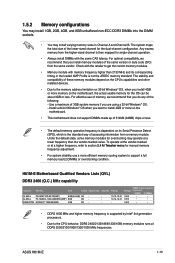
...devices. • Due to the CPU behavior, DDR3 2400/2133/1866/1333/1066 memory modules runs at DDR3 2200/2100/1800/1300/1000 MHz frequencies. H61M-E Motherboard Qualified Vendors Lists (QVL) DDR3 2400 (O.C.) MHz capability Vendors G.SKILL G.SKILL KINGSTON Part No. Chip NO. Voltage 1.65V 1.65V 1.65V...install 4GB or more on the motherboard. • This motherboard does not support DIMMs made up of accessing information from the same vendor. ASUS H61M-E 1-13 Under the default state, some memory modules for the OS can be about 3GB or less. To operate at the vendor-marked ...
...devices. • Due to the CPU behavior, DDR3 2400/2133/1866/1333/1066 memory modules runs at DDR3 2200/2100/1800/1300/1000 MHz frequencies. H61M-E Motherboard Qualified Vendors Lists (QVL) DDR3 2400 (O.C.) MHz capability Vendors G.SKILL G.SKILL KINGSTON Part No. Chip NO. Voltage 1.65V 1.65V 1.65V...install 4GB or more on the motherboard. • This motherboard does not support DIMMs made up of accessing information from the same vendor. ASUS H61M-E 1-13 Under the default state, some memory modules for the OS can be about 3GB or less. To operate at the vendor-marked ...
H61M-E User's Manual
Page 27
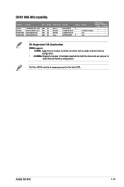
DDR3 1066 MHz capability Vendors Part No. Visit the ASUS website at www.asus.com for the latest QVL. ASUS H61M-E 1-15 Size Crucial CT25664BA1067.16FF 2GB ELPIDA EBJ21UE8EDF0-AE-F 2GB KINGSTON KVR1066D3N7/2G 2GB KINGSTON KVR1066D3N7/4G 4GB SS/DS DS DS DS DS Chip ...
DDR3 1066 MHz capability Vendors Part No. Visit the ASUS website at www.asus.com for the latest QVL. ASUS H61M-E 1-15 Size Crucial CT25664BA1067.16FF 2GB ELPIDA EBJ21UE8EDF0-AE-F 2GB KINGSTON KVR1066D3N7/2G 2GB KINGSTON KVR1066D3N7/4G 4GB SS/DS DS DS DS DS Chip ...
H61M-E User's Manual
Page 29
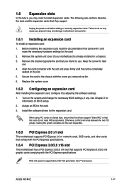
... support. Replace the system cover. 1.6.2 Configuring an expansion card After installing the expansion card, configure it and make the necessary hardware settings for later use . ASUS H61M-E 1-17 Remove the bracket opposite the slot that supports PCI Express 3.0/2.0 x16 graphic cards complying with the PCI Express specifications. When using PCI cards on...
... support. Replace the system cover. 1.6.2 Configuring an expansion card After installing the expansion card, configure it and make the necessary hardware settings for later use . ASUS H61M-E 1-17 Remove the bracket opposite the slot that supports PCI Express 3.0/2.0 x16 graphic cards complying with the PCI Express specifications. When using PCI cards on...
H61M-E User's Manual
Page 31
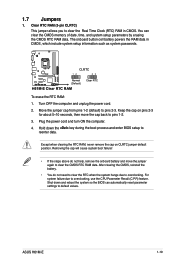
...the CPU Parameter Recall (C.P.R) feature. Plug the power cord and turn ON the computer. 4. Turn OFF the computer and unplug the power cord. 2. ASUS H61M-E 1-19 The onboard button cell battery powers the RAM data in CMOS. After clearing the CMOS, reinstall the battery. • You do not ...clear the CMOS RTC RAM data. 1.7 Jumpers 1. Clear RTC RAM (3-pin CLRTC) This jumper allows you to overclocking. CLRTC H61M-E 12 23 Normal (Default) Clear RTC H61M-E Clear RTC RAM To erase the RTC RAM: 1. Removing the cap will cause system boot failure! • If the steps...
...the CPU Parameter Recall (C.P.R) feature. Plug the power cord and turn ON the computer. 4. Turn OFF the computer and unplug the power cord. 2. ASUS H61M-E 1-19 The onboard button cell battery powers the RAM data in CMOS. After clearing the CMOS, reinstall the battery. • You do not ...clear the CMOS RTC RAM data. 1.7 Jumpers 1. Clear RTC RAM (3-pin CLRTC) This jumper allows you to overclocking. CLRTC H61M-E 12 23 Normal (Default) Clear RTC H61M-E Clear RTC RAM To erase the RTC RAM: 1. Removing the cap will cause system boot failure! • If the steps...
H61M-E User's Manual
Page 33
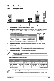
... port (light blue). Refer to the table below for the LAN port LED indications. This port allows Gigabit connection to a PS/2 mouse. 2. Microphone port (pink). ASUS H61M-E 1-21 This port connects to a microphone. Refer to the audio configuration table below for the function of this port becomes Front Speaker Out. 5. This port...
... port (light blue). Refer to the table below for the LAN port LED indications. This port allows Gigabit connection to a PS/2 mouse. 2. Microphone port (pink). ASUS H61M-E 1-21 This port connects to a microphone. Refer to the audio configuration table below for the function of this port becomes Front Speaker Out. 5. This port...
H61M-E User's Manual
Page 35
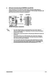
...orientation and push down firmly until the connectors completely fit. com/PowerSupplyCalculator/PSCalculator.aspx?SLanguage=en-us for ATX power supply plugs. ASUS H61M-E 1-23 The power supply plugs are uncertain about the minimum power supply requirement for your system, refer to the Recommended Power... +12V DC +12V DC +3 Volts +12 Volts +12 Volts +5V Standby Power OK PIN 1 GND GND GND +5 Volts GND +5 Volts H61M-E GND +3 Volts +3 Volts PIN 1 H61M-E ATX power connectors GND +5 Volts +5 Volts +5 Volts -5 Volts GND GND GND PSON# GND -12 Volts +3 Volts • For a ...
...orientation and push down firmly until the connectors completely fit. com/PowerSupplyCalculator/PSCalculator.aspx?SLanguage=en-us for ATX power supply plugs. ASUS H61M-E 1-23 The power supply plugs are uncertain about the minimum power supply requirement for your system, refer to the Recommended Power... +12V DC +12V DC +3 Volts +12 Volts +12 Volts +5V Standby Power OK PIN 1 GND GND GND +5 Volts GND +5 Volts H61M-E GND +3 Volts +3 Volts PIN 1 H61M-E ATX power connectors GND +5 Volts +5 Volts +5 Volts -5 Volts GND GND GND PSON# GND -12 Volts +3 Volts • For a ...
H61M-E User's Manual
Page 37
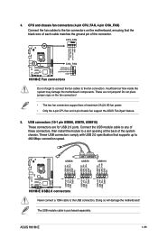
... cable matches the ground pin of maximum 2A (24 W) fan power. • Only the 4-pin CPU fan and 4-pin chassis fan support the ASUS Fan Xpert feature. 5. The USB module cable is purchased separately. Do not place jumper caps on the motherboard, ensuring that supports up to the USB... at the back of these connectors, then install the module to the fan connectors. Connect the USB module cable to any of the system chassis. ASUS H61M-E 1-25 USB connectors (10-1 pin USB56, USB78, USB910) These connectors are not jumpers! USB56 USB78 USB910 USB+5V USB_P6USB_P6+ GND NC USB+5V ...
... cable matches the ground pin of maximum 2A (24 W) fan power. • Only the 4-pin CPU fan and 4-pin chassis fan support the ASUS Fan Xpert feature. 5. The USB module cable is purchased separately. Do not place jumper caps on the motherboard, ensuring that supports up to the USB... at the back of these connectors, then install the module to the fan connectors. Connect the USB module cable to any of the system chassis. ASUS H61M-E 1-25 USB connectors (10-1 pin USB56, USB78, USB910) These connectors are not jumpers! USB56 USB78 USB910 USB+5V USB_P6USB_P6+ GND NC USB+5V ...
H61M-E User's Manual
Page 39
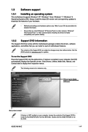
... The Support DVD that comes with the motherboard package contains the drivers, software applications, and utilities that you can install to change at www.asus.com for reference only. Double-click the ASSETUP.EXE to display their respective menus. Always install the latest OS version and corresponding updates to ...Vista / Windows® 7 / Windows® 8 Operating Systems (OS). The contents of your computer, the DVD automatically displays the Specials screen. If Autorun is for updates. ASUS H61M-E 1-27 Visit the ASUS website at any time without notice. To run the DVD.
... The Support DVD that comes with the motherboard package contains the drivers, software applications, and utilities that you can install to change at www.asus.com for reference only. Double-click the ASSETUP.EXE to display their respective menus. Always install the latest OS version and corresponding updates to ...Vista / Windows® 7 / Windows® 8 Operating Systems (OS). The contents of your computer, the DVD automatically displays the Specials screen. If Autorun is for updates. ASUS H61M-E 1-27 Visit the ASUS website at any time without notice. To run the DVD.
H61M-E User's Manual
Page 41
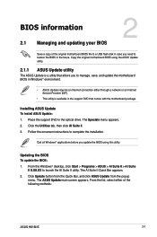
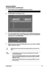
...disk in case you to manage, save, and update the motherboard BIOS in Windows® environment. • ASUS Update requires an Internet connection either of the following methods: ASUS H61M-E 2-1 Updating the BIOS To update the BIOS: 1. Place the support DVD in the future. Click Update... button from the Quick Bar, and click ASUS Update from the popup menu. The Specials menu appears. 2. ...
...disk in case you to manage, save, and update the motherboard BIOS in Windows® environment. • ASUS Update requires an Internet connection either of the following methods: ASUS H61M-E 2-1 Updating the BIOS To update the BIOS: 1. Place the support DVD in the future. Click Update... button from the Quick Bar, and click ASUS Update from the popup menu. The Specials menu appears. 2. ...
H61M-E User's Manual
Page 43
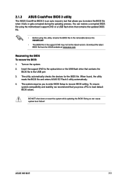
... system compatibility and stability, we recommend that you press to the USB port. 3. The utility automatically checks the devices for the BIOS file. ASUS H61M-E 2-3 Recovering the BIOS To recover the BIOS: 1. DO NOT shut down or reset the system while updating the BIOS! Turn on the ...may not be the latest version. When found, the utility reads the BIOS file and enters ASUS EZ Flash 2 utility automatically. 4. You can cause system boot failure! 2.1.3 ASUS CrashFree BIOS 3 utility The ASUS CrashFree BIOS 3 is an auto recovery tool that allows you to recover BIOS setting.
... system compatibility and stability, we recommend that you press to the USB port. 3. The utility automatically checks the devices for the BIOS file. ASUS H61M-E 2-3 Recovering the BIOS To recover the BIOS: 1. DO NOT shut down or reset the system while updating the BIOS! Turn on the ...may not be the latest version. When found, the utility reads the BIOS file and enters ASUS EZ Flash 2 utility automatically. 4. You can cause system boot failure! 2.1.3 ASUS CrashFree BIOS 3 utility The ASUS CrashFree BIOS 3 is an auto recovery tool that allows you to recover BIOS setting.
H61M-E User's Manual
Page 45
... to switch between screen fields and use the keys to exit BIOS Updater. Refer to section 2.9 Exit menu for DOS V1.30 Current ROM BOARD: H61M-E VER: 0303 DATE: 11/07/2012 Update ROM BOARD: Unknown VER: Unknown DATE: Unknown PATH: A:\ A: H61ME.CAP 8390656 2012-11-07 17:30...them. Restart your computer. Select Yes and press . Select the Load Optimized Defaults item under the Exit menu. The BIOS Updater screen appears as below. ASUS H61M-E 2-5 DO NOT shut down or reset the system while updating the BIOS to prevent system boot failure! • For BIOS Updater version 1.30 or...
... to switch between screen fields and use the keys to exit BIOS Updater. Refer to section 2.9 Exit menu for DOS V1.30 Current ROM BOARD: H61M-E VER: 0303 DATE: 11/07/2012 Update ROM BOARD: Unknown VER: Unknown DATE: Unknown PATH: A:\ A: H61ME.CAP 8390656 2012-11-07 17:30...them. Restart your computer. Select Yes and press . Select the Load Optimized Defaults item under the Exit menu. The BIOS Updater screen appears as below. ASUS H61M-E 2-5 DO NOT shut down or reset the system while updating the BIOS to prevent system boot failure! • For BIOS Updater version 1.30 or...
H61M-E User's Manual
Page 47
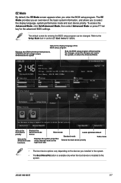
... the Setup Mode item in section 2.7 Boot menu for the advanced BIOS settings. The default screen for entering the BIOS setup program can be changed. ASUS H61M-E 2-7
... the Setup Mode item in section 2.7 Boot menu for the advanced BIOS settings. The default screen for entering the BIOS setup program can be changed. ASUS H61M-E 2-7
H61M-E User's Manual
Page 49
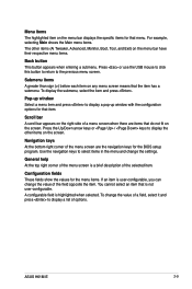
... return to display a pop-up window with the configuration options for that item. Configuration fields These fields show the values for the BIOS setup program. ASUS H61M-E 2-9 Press the Up/Down arrow keys or / keys to display a list of the menu screen are items that do not fit on the menu bar...
... return to display a pop-up window with the configuration options for that item. Configuration fields These fields show the values for the BIOS setup program. ASUS H61M-E 2-9 Press the Up/Down arrow keys or / keys to display a list of the menu screen are items that do not fit on the menu bar...
H61M-E User's Manual
Page 51
... in the BIOS setup program. From the Create New Password box, key in changing a user password, but press when prompted to create/confirm the password. ASUS H61M-E 2-11
... in the BIOS setup program. From the Create New Password box, key in changing a user password, but press when prompted to create/confirm the password. ASUS H61M-E 2-11


