
F2A55-M LK User's Manual
Page 1
Motherboard F2A55-M LK Series • F2A55-M LK • F2A55-M LK PLUS
Motherboard F2A55-M LK Series • F2A55-M LK • F2A55-M LK PLUS
F2A55-M LK User's Manual
Page 11
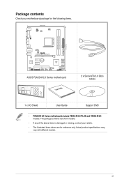
Package contents Check your retailer. • The illustrated items above items is damaged or missing, contact your motherboard package for reference only. The package contents vary from models. • If any of the above are for...USB34 LAN_USB12 COM CHA_FAN AUDIO RTL 8111F Super I/O F2A55-M LK PLUS PCIEX16 PCIEX1_1 Lithium Cell CMOS Power PCIEX1_2 AMD® A55 SB_PWR SATA3G_4 SATA3G_3 SATA3G_2 ALC 887 SPDIF_OUT AAFP PCI1 LPT USB910 USB78 USBPW5-10 USB56 CLRTC 64Mb BIOS SATA3G_1 SPEAKER F_PANEL ASUS F2A55-M LK Series motherboard User Guide 2 x Serial ATA 3.0 Gb/s cables...
Package contents Check your retailer. • The illustrated items above items is damaged or missing, contact your motherboard package for reference only. The package contents vary from models. • If any of the above are for...USB34 LAN_USB12 COM CHA_FAN AUDIO RTL 8111F Super I/O F2A55-M LK PLUS PCIEX16 PCIEX1_1 Lithium Cell CMOS Power PCIEX1_2 AMD® A55 SB_PWR SATA3G_4 SATA3G_3 SATA3G_2 ALC 887 SPDIF_OUT AAFP PCI1 LPT USB910 USB78 USBPW5-10 USB56 CLRTC 64Mb BIOS SATA3G_1 SPEAKER F_PANEL ASUS F2A55-M LK Series motherboard User Guide 2 x Serial ATA 3.0 Gb/s cables...
F2A55-M LK User's Manual
Page 13
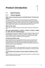
... ASUS F2A55-M LK Series 1-1 It features Dualchannel DDR3 memory support and accelerates data transfer rate up to 5GT/s interface speed and 6 x SATA 3.0Gb/s ports. Dual-Channel DDR3 2400(O.C.) / 2250(O.C.) / 2200(O.C.) / 2133(O.C.) / 2000(O. C.) / 1866 / 1600 / 1333 / 1066 MHz Support The motherboard... series graphics This motherboard supports AMD® A-series accelerated processor with an ACPI management function to provide efficient power management for advanced operating systems. 100% All High-quality Conductive Polymer Capacitors (F2A55-M LK PLUS only) This motherboard uses all high-...
... ASUS F2A55-M LK Series 1-1 It features Dualchannel DDR3 memory support and accelerates data transfer rate up to 5GT/s interface speed and 6 x SATA 3.0Gb/s ports. Dual-Channel DDR3 2400(O.C.) / 2250(O.C.) / 2200(O.C.) / 2133(O.C.) / 2000(O. C.) / 1866 / 1600 / 1333 / 1066 MHz Support The motherboard... series graphics This motherboard supports AMD® A-series accelerated processor with an ACPI management function to provide efficient power management for advanced operating systems. 100% All High-quality Conductive Polymer Capacitors (F2A55-M LK PLUS only) This motherboard uses all high-...

F2A55-M LK User's Manual
Page 16
...off the ATX power supply and detach its power cord. The illustration below shows the location of the following precautions before you install motherboard components or change any motherboard settings. • Unplug the power cord from the wall socket before removing or plugging in the bag that came with a standby... avoid damaging them . • Whenever you uninstall any component, place it on a grounded antistatic pad or in any component, switch off mode. SB_PWR F2A55-M LK PLUS ON OFF Standby Power Powered Off F2A55-M LK PLUS Onboard LED 1-4 Chapter 1: Product introduction
...off the ATX power supply and detach its power cord. The illustration below shows the location of the following precautions before you install motherboard components or change any motherboard settings. • Unplug the power cord from the wall socket before removing or plugging in the bag that came with a standby... avoid damaging them . • Whenever you uninstall any component, place it on a grounded antistatic pad or in any component, switch off mode. SB_PWR F2A55-M LK PLUS ON OFF Standby Power Powered Off F2A55-M LK PLUS Onboard LED 1-4 Chapter 1: Product introduction

F2A55-M LK User's Manual
Page 17
Doing so can damage the motherboard. Place this side towards the rear of the chassis as indicated in the image below. 1.3.2 Screw holes Place six screws into the chassis in the correct orientation. The edge with external ports goes to the rear part of the chassis. DO NOT overtighten the screws! F2A55-M LK PLUS ASUS F2A55-M LK Series 1-5 1.3 Motherboard overview 1.3.1 Placement direction When installing the motherboard, ensure that you place it into the holes indicated by circles to secure the motherboard to the chassis.
Doing so can damage the motherboard. Place this side towards the rear of the chassis as indicated in the image below. 1.3.2 Screw holes Place six screws into the chassis in the correct orientation. The edge with external ports goes to the rear part of the chassis. DO NOT overtighten the screws! F2A55-M LK PLUS ASUS F2A55-M LK Series 1-5 1.3 Motherboard overview 1.3.1 Placement direction When installing the motherboard, ensure that you place it into the holes indicated by circles to secure the motherboard to the chassis.
F2A55-M LK User's Manual
Page 18
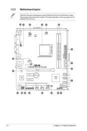
... 5 RTL 8111F Super I/O F2A55-M LK PLUS PCIEX16 PCIEX1_1 Lithium Cell CMOS Power PCIEX1_2 SB_PWR 8 AMD® A55 SATA3G_4 SATA3G_3 SATA3G_2 7 ALC 887 SPDIF_OUT AAFP PCI1 LPT USB910 USB78 USBPW5-10 USB56 CLRTC 64Mb BIOS SATA3G_1 SPEAKER F_PANEL 2 15 14 13 12 11 10 9 1-6 Chapter 1: Product introduction 1.3.3 Motherboard layout F2A55-M LK Series motherboards include F2A55-M LK PLUS and F2A55-M LK models. The package...
... 5 RTL 8111F Super I/O F2A55-M LK PLUS PCIEX16 PCIEX1_1 Lithium Cell CMOS Power PCIEX1_2 SB_PWR 8 AMD® A55 SATA3G_4 SATA3G_3 SATA3G_2 7 ALC 887 SPDIF_OUT AAFP PCI1 LPT USB910 USB78 USBPW5-10 USB56 CLRTC 64Mb BIOS SATA3G_1 SPEAKER F_PANEL 2 15 14 13 12 11 10 9 1-6 Chapter 1: Product introduction 1.3.3 Motherboard layout F2A55-M LK Series motherboards include F2A55-M LK PLUS and F2A55-M LK models. The package...

F2A55-M LK User's Manual
Page 19
... connectors (7-pin SATA3G_1~6) 8. The APU fits in only one correct orientation. DDR3 DIMM slots 7. Speaker connector (4-pin SPEAKER) 11. F2A55-M LK PLUS F2A55-M LK PLUS APU socket FM2 ASUS F2A55-M LK Series 1-7 LPT connector (26-1 pin LPT) 14. USB 2.0 connectors (10-1 pin USB56, USB78, USB910) 13. Standby power LED...24 1-7 1-23 1-11 1-25 1-4 1-26 1-26 1-20 1-28 1-25 1-27 1-27 1-28 1.4 Accelerated Processing Unit (APU) This motherboard comes with AMD® Radeon™ HD 7000 series graphics. System panel connector (10-1 pin F_PANEL) 10. ATX power connectors (24-pin EATXPWR...
... connectors (7-pin SATA3G_1~6) 8. The APU fits in only one correct orientation. DDR3 DIMM slots 7. Speaker connector (4-pin SPEAKER) 11. F2A55-M LK PLUS F2A55-M LK PLUS APU socket FM2 ASUS F2A55-M LK Series 1-7 LPT connector (26-1 pin LPT) 14. USB 2.0 connectors (10-1 pin USB56, USB78, USB910) 13. Standby power LED...24 1-7 1-23 1-11 1-25 1-4 1-26 1-26 1-20 1-28 1-25 1-27 1-27 1-28 1.4 Accelerated Processing Unit (APU) This motherboard comes with AMD® Radeon™ HD 7000 series graphics. System panel connector (10-1 pin F_PANEL) 10. ATX power connectors (24-pin EATXPWR...

F2A55-M LK User's Manual
Page 23
DDR3 modules are developed for better performance with two Double Data Rate 3 (DDR3) Dual Inline Memory Modules (DIMM) sockets. 1.5 System memory 1.5.1 Overview This motherboard comes with less power consumption. The figure illustrates the location of the DDR3 DIMM sockets: DIMM_A1 DIMM_B1 F2A55-M LK PLUS Channel Channel A Channel B F2A55-M LK PLUS 240-pin DDR3 DIMM sockets Sockets DIMM_A1 DIMM_B1 ASUS F2A55-M LK Series 1-11 A DDR3 module has the same physical dimensions as a DDR2 DIMM but is notched differently to prevent installation on a DDR2 DIMM socket.
DDR3 modules are developed for better performance with two Double Data Rate 3 (DDR3) Dual Inline Memory Modules (DIMM) sockets. 1.5 System memory 1.5.1 Overview This motherboard comes with less power consumption. The figure illustrates the location of the DDR3 DIMM sockets: DIMM_A1 DIMM_B1 F2A55-M LK PLUS Channel Channel A Channel B F2A55-M LK PLUS 240-pin DDR3 DIMM sockets Sockets DIMM_A1 DIMM_B1 ASUS F2A55-M LK Series 1-11 A DDR3 module has the same physical dimensions as a DDR2 DIMM but is notched differently to prevent installation on a DDR2 DIMM socket.
F2A55-M LK User's Manual
Page 35
...CPU FAN PWR GND F2A55-M LK PLUS CHA_FAN Rotation +12V GND F2A55-M LK PLUS Fan connectors DO NOT forget to connect the fan cables to CRT and isn't compatible with DVI-I. 10. PS/2 Keyboard port (purple). DO NOT place jumper caps on the motherboard, ensuring that the ... and 2. Insufficient air flow inside the system may damage the motherboard components. Video Graphics Adapter (VGA) port. This port is for any DVI-D compatible device. DVI-D can't be converted to output RGB Signal to the fan connectors. ASUS F2A55-M LK Series 1-23 These are for USB 2.0/1.1 devices. 7. These...
...CPU FAN PWR GND F2A55-M LK PLUS CHA_FAN Rotation +12V GND F2A55-M LK PLUS Fan connectors DO NOT forget to connect the fan cables to CRT and isn't compatible with DVI-I. 10. PS/2 Keyboard port (purple). DO NOT place jumper caps on the motherboard, ensuring that the ... and 2. Insufficient air flow inside the system may damage the motherboard components. Video Graphics Adapter (VGA) port. This port is for any DVI-D compatible device. DVI-D can't be converted to output RGB Signal to the fan connectors. ASUS F2A55-M LK Series 1-23 These are for USB 2.0/1.1 devices. 7. These...
F2A55-M LK User's Manual
Page 39
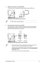
ASUS F2A55-M LK Series 1-27 Front panel audio connector (10-1 pin AAFP) This connector is purchased separately. See section 2.5.5 Onboard Devices Configuration for details. • The front panel audio I /O module cable to [HD]. F2A55-M LK PLUS SPDIF_OUT F2A55-M LK PLUS Digital audio connector The S/...PDIF module is for a chassis-mounted front panel audio I/O module that you connect a high-definition front panel audio module to this connector to avail of the motherboard high-definition audio ...
ASUS F2A55-M LK Series 1-27 Front panel audio connector (10-1 pin AAFP) This connector is purchased separately. See section 2.5.5 Onboard Devices Configuration for details. • The front panel audio I /O module cable to [HD]. F2A55-M LK PLUS SPDIF_OUT F2A55-M LK PLUS Digital audio connector The S/...PDIF module is for a chassis-mounted front panel audio I/O module that you connect a high-definition front panel audio module to this connector to avail of the motherboard high-definition audio ...

F2A55-M LK User's Manual
Page 40
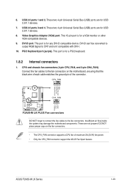
COM RXD DTR DSR CTS PIN 1 DCD TXD GND RTS RI F2A55-M LK PLUS F2A55-M LK PLUS Serial port (COM) connector The COM module is for USB 2.0 ports. Serial port connector (10-1 pin COM...USB_P8USB_P8+ GND NC USB+5V USB_P6USB_P6+ GND NC USB+5V USB_P9USB_P9+ GND USB+5V USB_P7USB_P7+ GND USB+5V USB_P5USB_P5+ GND F2A55-M LK PLUS PIN 1 PIN 1 PIN 1 F2A55-M LK PLUS USB2.0 connectors Never connect a 1394 cable to a slot opening at the back of the system chassis. The USB 2.0... this connector, then install the module to 480Mbps connection speed. Doing so will damage the motherboard!
COM RXD DTR DSR CTS PIN 1 DCD TXD GND RTS RI F2A55-M LK PLUS F2A55-M LK PLUS Serial port (COM) connector The COM module is for USB 2.0 ports. Serial port connector (10-1 pin COM...USB_P8USB_P8+ GND NC USB+5V USB_P6USB_P6+ GND NC USB+5V USB_P9USB_P9+ GND USB+5V USB_P7USB_P7+ GND USB+5V USB_P5USB_P5+ GND F2A55-M LK PLUS PIN 1 PIN 1 PIN 1 F2A55-M LK PLUS USB2.0 connectors Never connect a 1394 cable to a slot opening at the back of the system chassis. The USB 2.0... this connector, then install the module to 480Mbps connection speed. Doing so will damage the motherboard!
F2A55-M LK User's Manual
Page 45
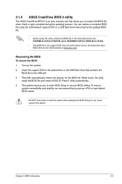
...Turn on the system. 2. To ensure system compatibility and stability, we recommend that contains the updated BIOS file. • Before using the motherboard support DVD or a USB flash drive that you press to load default BIOS values. You can cause system boot failure! Insert the support DVD...reads the BIOS file and enters ASUS EZ Flash 2 utility automatically. 4. Download the latest BIOS file from the ASUS website at www.asus.com. DO NOT shut down or reset the system while updating the BIOS! The utility automatically checks the devices for F2A55-M LK PLUS). • The BIOS file ...
...Turn on the system. 2. To ensure system compatibility and stability, we recommend that contains the updated BIOS file. • Before using the motherboard support DVD or a USB flash drive that you press to load default BIOS values. You can cause system boot failure! Insert the support DVD...reads the BIOS file and enters ASUS EZ Flash 2 utility automatically. 4. Download the latest BIOS file from the ASUS website at www.asus.com. DO NOT shut down or reset the system while updating the BIOS! The utility automatically checks the devices for F2A55-M LK PLUS). • The BIOS file ...
F2A55-M LK User's Manual
Page 49
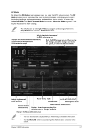
...Default(F5) Selects the Advanced mode functions Power Saving mode Normal mode Loads optimized default ASUS Optimal mode Selects the boot device priority Selects the boot device priority Displays the system...program. The default screen for the advanced BIOS settings. EZ Mode Friday [10/08/2010] F2A55-M LK PLUS BIOS Version : 0301 CPU Type : AMD A8-5600K APU with Radeon(tm) HD Graphics ... 2: BIOS information 2-7 Selects the display language of the BIOS setup program Displays the CPU/motherboard temperature, CPU/5V/3.3V/12V voltage output, CPU/chassis fan speed Exits the BIOS setup ...
...Default(F5) Selects the Advanced mode functions Power Saving mode Normal mode Loads optimized default ASUS Optimal mode Selects the boot device priority Selects the boot device priority Displays the system...program. The default screen for the advanced BIOS settings. EZ Mode Friday [10/08/2010] F2A55-M LK PLUS BIOS Version : 0301 CPU Type : AMD A8-5600K APU with Radeon(tm) HD Graphics ... 2: BIOS information 2-7 Selects the display language of the BIOS setup program Displays the CPU/motherboard temperature, CPU/5V/3.3V/12V voltage output, CPU/chassis fan speed Exits the BIOS setup ...
F2A55-M LK User's Manual
Page 78
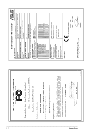
Appendices A-4 DECLARATION OF CONFORMITY Per FCC Part 2 Section 2. 1077(a) Responsible Party Name: Asus Computer International Address: 800 Corporate Way, Fremont, CA 94539. No. 150, LI-TE RD., PEITOU, TAIPEI...Name : Motherboard Model Number : F2A55-M LK, F2A55-M LK PLUS Conforms to begin affixing CE marking:2012 Signature Country: TAIWAN Authorized representative in Europe: ASUS COMPUTER GmbH Address, City: HARKORT STR. 21-23, 40880 RATINGEN Country: GERMANY declare the following apparatus: Product name : Motherboard Model name : F2A55-M LK, F2A55-M LK PLUS conform with...
Appendices A-4 DECLARATION OF CONFORMITY Per FCC Part 2 Section 2. 1077(a) Responsible Party Name: Asus Computer International Address: 800 Corporate Way, Fremont, CA 94539. No. 150, LI-TE RD., PEITOU, TAIPEI...Name : Motherboard Model Number : F2A55-M LK, F2A55-M LK PLUS Conforms to begin affixing CE marking:2012 Signature Country: TAIWAN Authorized representative in Europe: ASUS COMPUTER GmbH Address, City: HARKORT STR. 21-23, 40880 RATINGEN Country: GERMANY declare the following apparatus: Product name : Motherboard Model name : F2A55-M LK, F2A55-M LK PLUS conform with...


