
Series User Manual
Page 5
... 5.6.12 Network Stack Configuration 5-27 5.6.13 iSCSI Configuration 5-28 5.7 Platform Configuration menu 5-28 5.7.1 PCH Configuration 5-29 5.7.2 Miscellaneous Configuration 5-31 5.7.3 Server ME Configuration 5-31 5.7.4 Runtime Error Logging Support 5-32 5.8 Socket Configuration menu 5-32 5.8.1 Processor Configuration 5-33 5.8.2 Common RefCode Configuration 5-34 5.8.3 ...Logs menu 5-41 5.9.1 Change Smbios Event Log Settings 5-41 5.9.2 View Smbios Event Log 5-41 5.10 Server Mgmt menu 5-42 5.11 Security menu 5-43 5.12 Boot menu 5-46 5.13 Tool menu 5-47 5.14 Save & Exit menu 5-47 v
... 5.6.12 Network Stack Configuration 5-27 5.6.13 iSCSI Configuration 5-28 5.7 Platform Configuration menu 5-28 5.7.1 PCH Configuration 5-29 5.7.2 Miscellaneous Configuration 5-31 5.7.3 Server ME Configuration 5-31 5.7.4 Runtime Error Logging Support 5-32 5.8 Socket Configuration menu 5-32 5.8.1 Processor Configuration 5-33 5.8.2 Common RefCode Configuration 5-34 5.8.3 ...Logs menu 5-41 5.9.1 Change Smbios Event Log Settings 5-41 5.9.2 View Smbios Event Log 5-41 5.10 Server Mgmt menu 5-42 5.11 Security menu 5-43 5.12 Boot menu 5-46 5.13 Tool menu 5-47 5.14 Save & Exit menu 5-47 v

Series User Manual
Page 8
... Battery Warning CAUTION! Danger of used batteries according to fix it by certified or experienced engineers. • Before operating the server, carefully read all the manuals included with a properly grounded electrical outlet to or from the system, ensure that the power ...the manufacturer's instructions. viii If possible, disconnect all cables are correctly connected and the power cables are connected. Place the server on this server must be conducted by yourself. Dispose of explosion if battery is detected, contact your dealer. Safety information Electrical Safety &#...
... Battery Warning CAUTION! Danger of used batteries according to fix it by certified or experienced engineers. • Before operating the server, carefully read all the manuals included with a properly grounded electrical outlet to or from the system, ensure that the power ...the manufacturer's instructions. viii If possible, disconnect all cables are correctly connected and the power cables are connected. Place the server on this server must be conducted by yourself. Dispose of explosion if battery is detected, contact your dealer. Safety information Electrical Safety &#...
Series User Manual
Page 9
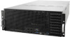
...Installation This chapter provides instructions for installing the necessary drivers for system integrators, and experienced users with the server. Detailed descriptions of the server, including sections on front panel and rear panel specifications. 2. Chapter 1: Product Introduction This chapter describes... 4: Motherboard Information This chapter gives information about the motherboard that you have to install optional components into the barebone server. 4. ix This chapter includes the motherboard layout, jumper settings, and connector locations. 5. About this guide Audience This...
...Installation This chapter provides instructions for installing the necessary drivers for system integrators, and experienced users with the server. Detailed descriptions of the server, including sections on front panel and rear panel specifications. 2. Chapter 1: Product Introduction This chapter describes... 4: Motherboard Information This chapter gives information about the motherboard that you have to install optional components into the barebone server. 4. ix This chapter includes the motherboard layout, jumper settings, and connector locations. 5. About this guide Audience This...

Series User Manual
Page 10
... note of the following sources for additional information, and for all ASUS hardware and software products. CAUTION: Information to prevent damage to the components when trying to set up and use the proprietary ASUS server management utility. 2. Example: means that you must press the Enter... or Return key. ASUS Control Center (ACC) user guide This manual tells how to complete a task. IMPORTANT: ...
... note of the following sources for additional information, and for all ASUS hardware and software products. CAUTION: Information to prevent damage to the components when trying to set up and use the proprietary ASUS server management utility. 2. Example: means that you must press the Enter... or Return key. ASUS Control Center (ACC) user guide This manual tells how to complete a task. IMPORTANT: ...
Series User Manual
Page 12
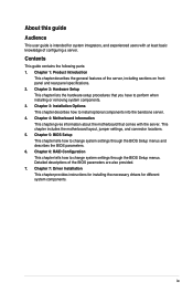
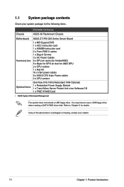
.... 1-2 Chapter 1: Product Introduction If any of the above items is damaged or missing, contact your system package for the following items. ESC8000 G4 Series Chassis ASUS 4U Rackmount Chassis Motherboard ASUS Z11PG-D24 Series Server Board Accessory box 1 x MB Support DVD 1 x ACC instruction card 1 x ASMB9 instruction card 2 x Front PIKE II cables 1 x Bag of Screws 3 x AC...
.... 1-2 Chapter 1: Product Introduction If any of the above items is damaged or missing, contact your system package for the following items. ESC8000 G4 Series Chassis ASUS 4U Rackmount Chassis Motherboard ASUS Z11PG-D24 Series Server Board Accessory box 1 x MB Support DVD 1 x ACC instruction card 1 x ASMB9 instruction card 2 x Front PIKE II cables 1 x Bag of Screws 3 x AC...

Series User Manual
Page 14
The server supports Intel® Xeon® Scalable Processors Family Series plus other latest technologies through the chipsets onboard. Model Name ESC8000 G4 ESC8000 G4/10G Processor / System Bus Core Logic 2 x...Optane™ DC persistent memory (DCPMM) * 2933MHz will drop to 2666MHz when using 2DPC configurations ** Refer to ASUS server AVL for the latest update 4GB, 8GB, 12GB, 32GB (RDIMM) 64GB, 128GB (RDIMM 3DS) 32GB, 64GB,...(continued on the next page) 1-4 Chapter 1: Product Introduction 1.3 System specifications The ASUS ESC8000 G4 Series servers features the ASUS Z11PG-D24 Series...
The server supports Intel® Xeon® Scalable Processors Family Series plus other latest technologies through the chipsets onboard. Model Name ESC8000 G4 ESC8000 G4/10G Processor / System Bus Core Logic 2 x...Optane™ DC persistent memory (DCPMM) * 2933MHz will drop to 2666MHz when using 2DPC configurations ** Refer to ASUS server AVL for the latest update 4GB, 8GB, 12GB, 32GB (RDIMM) 64GB, 128GB (RDIMM 3DS) 32GB, 64GB,...(continued on the next page) 1-4 Chapter 1: Product Introduction 1.3 System specifications The ASUS ESC8000 G4 Series servers features the ASUS Z11PG-D24 Series...

Series User Manual
Page 17
ASUS ESC8000 G4 Series 1-7 The power and reset buttons, LED indicators, and USB ports are located on the front panel. Steel pull handle Location button with LED Power ... Access LED 1 2 3 4 5 6 7 8 2.5-inch Bay 1-8 1.5 Rear panel features The LAN ports and system power socket are located and easily accessible on the rear panel of the server. Half-length/Low-profile expansion slot Power cord connector and Redundant power supply LAN ports Locate LED Dedicated Management LAN port Full-length/Full-height...
ASUS ESC8000 G4 Series 1-7 The power and reset buttons, LED indicators, and USB ports are located on the front panel. Steel pull handle Location button with LED Power ... Access LED 1 2 3 4 5 6 7 8 2.5-inch Bay 1-8 1.5 Rear panel features The LAN ports and system power socket are located and easily accessible on the rear panel of the server. Half-length/Low-profile expansion slot Power cord connector and Redundant power supply LAN ports Locate LED Dedicated Management LAN port Full-length/Full-height...

Series User Manual
Page 18
... the protection film before shipping. Half-length/Low-profile PCIE Expansion slot (1 x Gen3 x8 link) 10. Connect a USB floppy disk drive to 22110) The barebone server does not include a floppy disk drive or an optical drive. Redundant Power Supply (hidden) 2. PCIE SKU board with two halflength/low-profile PCIE Expansion slots...
... the protection film before shipping. Half-length/Low-profile PCIE Expansion slot (1 x Gen3 x8 link) 10. Connect a USB floppy disk drive to 22110) The barebone server does not include a floppy disk drive or an optical drive. Redundant Power Supply (hidden) 2. PCIE SKU board with two halflength/low-profile PCIE Expansion slots...

Series User Manual
Page 28
...sockets. For more information, see the section Chassis cover. 2. For more information, see the section Air Duct. 3. Remove the air duct. ASUS will process Return Merchandise Authorization (RMA) requests only if the motherboard comes with a surface mount LGA 3647 socket designed for the Intel® .../removal, or misplacement/loss/incorrect removal of the PnP cap. 2.2.1 Installing the CPU and cooler To install a CPU: 1. ASUS will shoulder the cost of the server system, ensure that the PnP cap is shipment/ transit-related. • The product warranty does not cover damage to the...
...sockets. For more information, see the section Chassis cover. 2. For more information, see the section Air Duct. 3. Remove the air duct. ASUS will process Return Merchandise Authorization (RMA) requests only if the motherboard comes with a surface mount LGA 3647 socket designed for the Intel® .../removal, or misplacement/loss/incorrect removal of the PnP cap. 2.2.1 Installing the CPU and cooler To install a CPU: 1. ASUS will shoulder the cost of the server system, ensure that the PnP cap is shipment/ transit-related. • The product warranty does not cover damage to the...

Series User Manual
Page 32
... modules from the same vendor. and 128GB, 256GB, and 512GB DCPMMs into the DIMM sockets using the memory configurations in this section. • Refer to ASUS Server AVL for 1 CPU Configuration 1 CPU Configuration (must be on CPU1) DIMM_A2 DIMM_A1 DIMM_B2 DIMM_B1 DIMM_C2 DIMM_C1 1 DIMM • 2 DIMMs • 4 DIMMs • • 6 DIMMs •...
... modules from the same vendor. and 128GB, 256GB, and 512GB DCPMMs into the DIMM sockets using the memory configurations in this section. • Refer to ASUS Server AVL for 1 CPU Configuration 1 CPU Configuration (must be on CPU1) DIMM_A2 DIMM_A1 DIMM_B2 DIMM_B1 DIMM_C2 DIMM_C1 1 DIMM • 2 DIMMs • 4 DIMMs • • 6 DIMMs •...

Series User Manual
Page 42
... the front of half-length cards. Failure to do so may cause you physical injury and damage motherboard components. 2.5.1 The PCI Express riser card The server system comes pre-installed with a riser card that secure the riser card to detach it from the chassis. 2-20 Chapter 2: Hardware Setup Remove the two...
... the front of half-length cards. Failure to do so may cause you physical injury and damage motherboard components. 2.5.1 The PCI Express riser card The server system comes pre-installed with a riser card that secure the riser card to detach it from the chassis. 2-20 Chapter 2: Hardware Setup Remove the two...

Series User Manual
Page 57
... PSUs with different wattage (e.g. 1 x 1620 W + 1 x 2000 W) may yield unstable results and potential damage to your system. • For a steady power input, use PSUs with the server system package. The combined output power varies with input voltages. • To enable the hot-swap feature (redundant mode), keep the total power consumption of... maximum output power of an individual power supply module. • Always use only the power cables that come with the same watt and power rating. ASUS ESC8000 G4 Series 2-35
... PSUs with different wattage (e.g. 1 x 1620 W + 1 x 2000 W) may yield unstable results and potential damage to your system. • For a steady power input, use PSUs with the server system package. The combined output power varies with input voltages. • To enable the hot-swap feature (redundant mode), keep the total power consumption of... maximum output power of an individual power supply module. • Always use only the power cables that come with the same watt and power rating. ASUS ESC8000 G4 Series 2-35

Series User Manual
Page 58
... > PCIE6 > PCIE7. To install a GPU card to the system: 1. Metal shutter Metal covers 2-36 Chapter 2: Hardware Setup 2.8 Installing GPU cards • Use both of the server system (A), then remove the metal covers and the metal shutter from the chassis (B).
... > PCIE6 > PCIE7. To install a GPU card to the system: 1. Metal shutter Metal covers 2-36 Chapter 2: Hardware Setup 2.8 Installing GPU cards • Use both of the server system (A), then remove the metal covers and the metal shutter from the chassis (B).

Series User Manual
Page 62
GPU card power cable 6-pin GPU card power connector 8. Attach the other end of the GPU card into the PCIE slot on the middle of the server system (A), align and insert the golden fingers of the power cable (6-pin power connector) to install additional GPU cards. 2-40 Chapter 2: Hardware Setup Repeat steps 1-7 if you need to an available 6-pin power connector on the PCIE SKU board (B), then secure the GPU card with the two (2) screws that you removed earlier in step 1 (C). 7.
GPU card power cable 6-pin GPU card power connector 8. Attach the other end of the GPU card into the PCIE slot on the middle of the server system (A), align and insert the golden fingers of the power cable (6-pin power connector) to install additional GPU cards. 2-40 Chapter 2: Hardware Setup Repeat steps 1-7 if you need to an available 6-pin power connector on the PCIE SKU board (B), then secure the GPU card with the two (2) screws that you removed earlier in step 1 (C). 7.

Series User Manual
Page 63
Chapter 3: Installation Options Installation Options This chapter describes how to install the optional components and devices into the barebone server. 3
Chapter 3: Installation Options Installation Options This chapter describes how to install the optional components and devices into the barebone server. 3

Series User Manual
Page 64
... are required for the installation. • Package content and specifications are subject to change without a CMA, another 9" (for 1200 mm rack rails) or 2" (for your server system.
... are required for the installation. • Package content and specifications are subject to change without a CMA, another 9" (for 1200 mm rack rails) or 2" (for your server system.

Series User Manual
Page 67
ASUS ESC8000 G4 Series 3-5 7. Secure the inner rails on both sides of the server system until it locks in place. 8. Align the inner rails with the studs on both sides of the server system, install the inner rails to the server system, then slide the inner rails toward the rear of the server system using the #6-32X4L screws.
ASUS ESC8000 G4 Series 3-5 7. Secure the inner rails on both sides of the server system until it locks in place. 8. Align the inner rails with the studs on both sides of the server system, install the inner rails to the server system, then slide the inner rails toward the rear of the server system using the #6-32X4L screws.

Series User Manual
Page 68
Front rack post Front end of rack rail 11. Gently push the server system until it is used to a stop while you are installing the server system into the rack rails, slide the blue release tab outwards and gently push the server system until it into the rack rail. 9. Inner rail Intermediate rail Blue... tab is completely installed into the rack rails. 10. (optional) Use the M5X20L screws to secure the rack rails to the rack post. Align the server system and gently insert it is available on 1200 mm rack rails.
Front rack post Front end of rack rail 11. Gently push the server system until it is used to a stop while you are installing the server system into the rack rails, slide the blue release tab outwards and gently push the server system until it into the rack rail. 9. Inner rail Intermediate rail Blue... tab is completely installed into the rack rails. 10. (optional) Use the M5X20L screws to secure the rack rails to the rack post. Align the server system and gently insert it is available on 1200 mm rack rails.

Series User Manual
Page 70
... right for 1200 mm rack rails) You can install an additional cable management arm (CMA) to the rack rails to help you to move the server system along the rack rail without the need to remove the CMA. The CMA is designed with movable parts that allow you manage the cables... from your server system. Press the round button on the pivot receptor, then rotate the pivot receptor to section 3.1 Rail Kit for the steps on installing the rack...
... right for 1200 mm rack rails) You can install an additional cable management arm (CMA) to the rack rails to help you to move the server system along the rack rail without the need to remove the CMA. The CMA is designed with movable parts that allow you manage the cables... from your server system. Press the round button on the pivot receptor, then rotate the pivot receptor to section 3.1 Rail Kit for the steps on installing the rack...

Series User Manual
Page 72
Hook and loop fasteners Cable fasteners 3-10 Chapter 3: Installation Options 6. Align and connect the pivot receptor on the CMA with the connector on the CMA to complete. Pass the cables from the server system through the hook and loop fasteners and the cable fasteners on the other intermediate rail. 7.
Hook and loop fasteners Cable fasteners 3-10 Chapter 3: Installation Options 6. Align and connect the pivot receptor on the CMA with the connector on the CMA to complete. Pass the cables from the server system through the hook and loop fasteners and the cable fasteners on the other intermediate rail. 7.

