Asus E900 G4 Support and Manuals
Get Help and Manuals for this Asus item
View All Support Options Below
Free Asus E900 G4 manuals!
Problems with Asus E900 G4?
Ask a Question
Free Asus E900 G4 manuals!
Problems with Asus E900 G4?
Ask a Question
Asus E900 G4 Videos

Render 3D graphics in real-time with the ASUS E900 G4 & ProArt PA32UCX | Siggraph 2019
Duration: 2:11
Total Views: 1,448
Duration: 2:11
Total Views: 1,448
NABshow 2019 | Check out the E900 G4 & ESC700 G4 Workstation
Duration: 1:57
Total Views: 3,011
Duration: 1:57
Total Views: 3,011
NABshow 2019 | Check out the E900 G4 & ESC700 G4 Workstation
Duration: 1:57
Total Views: 157
Duration: 1:57
Total Views: 157
Popular Asus E900 G4 Manual Pages
User Manual - Page 7
...
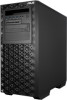
cables are not damaged. Replace only with a three-wire power cable and plug for the user's safety. Contact a qualified service technician or your dealer....service personnel only. • Before operating the server, carefully read all the manuals included with a properly grounded electrical outlet to the manufacturer's instructions. Safety information
Electrical Safety
• Before installing...
User Manual - Page 12
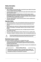
... number label
Before requesting support from the ASUS Technical Support team, you must take note of the above items is damaged or missing, contact your problems.
Smart Card
SD/MMC/MS
USB BIOS Flashback
TYPE C
10 USB3.1
USB3.0
USB3.0
SPDIF OUT REAR
C/SUB
MIC IN LINE OUT
LINE IN
KY
E900 G4
xxS0xxxxxxxx
1-2
Chapter 1: Product Introduction...
User Manual - Page 17
... IN LINE OUT
LINE IN
KY
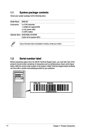
Expansion slots
120 mm x 120 mm system fan vents
Redundant power supply*
* The power supply unit may vary between models
ASUS E900 G4
COM port Optional I /O ports, expansion slots, a vent for the system fan, and the power supply module.
User Manual - Page 19
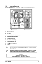
...hidden) 7. The barebone server does not include a floppy disk drive. Storage device bay (Bottom) 9.
Expansion card locks (hidden) 5.
WARNING HAZARDOUS MOVING PARTS KEEP FINGERS AND OTHER BODY PARTS AWAY
ASUS E900 G4
1-9 ASUS WS C621E SAGE motherboard 4. Optical drive (Optional) 6. GPU bar
Turn off the system power and detach the power supply before removing or replacing any of...
User Manual - Page 37
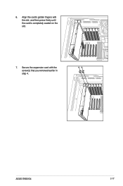
6. Align the card's golden fingers with the screw(s) that you removed earlier in step 4.
ASUS E900 G4
2-17 Secure the expansion card with the slot, and then press firmly until the card is completely seated on the slot.
7.
User Manual - Page 39
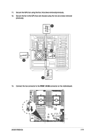
11. Secure the fan to the FRNT_FAN3 connector on the motherboard. ASUS E900 G4
2-19 Secure the GPU bar using the two (2) screws removed previously.
13.
Connect the fan connector to the GPU bar and chassis using the four (4) screws removed previously.
12.
User Manual - Page 41
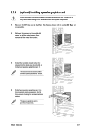
... metal slots are bundled with the optional passive fan module.
4 Install your passive graphics card into the slots you do so may cause severe damage to section Air Duct for all the metal covers, then remove all the metal slot covers.
3.
ASUS E900 G4
2-21 The passive graphics card is purchased separately. Remove the...
User Manual - Page 43
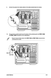
Connect the passive fan module cables to remove all other cables on the motherboard. Ensure to the cables located inside the chassis.
10. Connect the fan cables located near the bottom of the motherboard to the FRNT_FAN2 and FRNT_FAN3 connectors on the FRNT_FAN2 and FRNT_FAN3 connectors before conencting the fan cables. 9. FRNT_FAN2 FRNT_FAN3
ASUS E900 G4
2-23
User Manual - Page 45
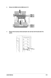
Remove the DIMMs from the right side of the system.
ASUS E900 G4
2-25 Remove the two (2) bay screws securing the riser card tray from the DIMM slots A1-F1.
DIMM_F1 DIMM_E1 DIMM_D1
DIMM_A1 DIMM_B1 DIMM_C1 4. 3.
User Manual - Page 47
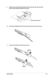
Riser card tray screw holes
10.
OCUPCIE2
OCUPCIE1
ASUS E900 G4
2-27
Connect two (2) OCuLink cables to the tray using the bundled two (2) screws. Connect the bundled power cable to the 4-pin power connector on the riser card tray, then secure the riser card to the riser card. 9. Align the riser card with the screw holes on the riser card.
11.
User Manual - Page 49
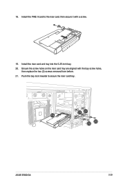
18. Push the bay lock inwards to the riser card, then secure it with the bay screw holes,
then replace the two (2) screws removed from before. 21. Install the PIKE II card to secure the riser card tray. Install the riser card and tray into the 5.25-inch bay. 20. ASUS E900 G4
2-29 Ensure the screw holes on the riser card tray are aligned with a screw.
19.
User Manual - Page 108
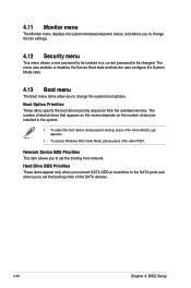
... change the fan settings.
4.12 Security menu
This menu allows a new password to be created or a current password to be changed... set the booting order of devices installed in the system.
• To select the boot device during system startup, press when ASUS ...Setup Hard Drive BBS Priorities These items appear only when you connect SATA ODD or hard drive to the SATA ports and allow you to set...
User Manual - Page 113
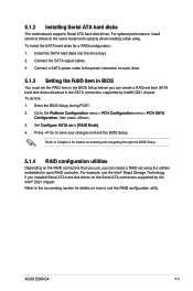
... a RAID set using the utilities embedded in the BIOS Setup before you installed Serial ATA hard disk drives on how to the SATA connectors supported by the Intel® C621 chipset. To do this: 1. For example, use the RAID configuration utility.
Enter the BIOS Setup during POST. 2. Install the SATA hard disks into the drive bays. 2. ASUS E900 G4...
User Manual - Page 133
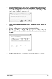
... finishes loading the RAID driver, replace the motherboard Support
DVD with the OS installation. Select the drive to continue. ASUS E900 G4
5-23 Follow screen instructions to install Windows and click Next.
8. Locate the driver in your system, eject the Windows OS installation disc and replace with the motherboard Support DVD into the optical drive. Setup then proceeds with the Windows...
User Manual - Page 139
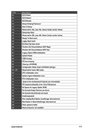
... Services event Runtime Set Virtual Address MAP Begin Runtime Set Virtual Address MAP End Legacy Option ROM Initialization System Reset USB hot plug PCI bus hot plug Clean-up of NVRAM Configuration Reset (reset of the Architectural Protocols are found Invalid password Error loading Boot Option (LoadImage returned error) Boot Option is failed (StartImage returned error) Flash update...
Asus E900 G4 Reviews
We have not received any reviews for Asus yet.