
A8V-MX User''s Manual for English Edition
Page 1
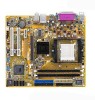
A8V-MX Motherboard
A8V-MX Motherboard

A8V-MX User''s Manual for English Edition
Page 3
Contents Notices vi Safety information vii A8V-MX specifications summary viii Chapter 1: Product introduction 1.1 Welcome 1-2 1.2 Package contents 1-2 1.3 Special features 1-2 1.3.1 Product highlights 1-2 1.3.2 Innovative ASUS features 1-4 1.4 Before you proceed 1-5 1.5 Motherboard overview 1-6 1.5.1 Motherboard layout 1-6 1.5.2 Placement direction 1-7 1.5.3 Screw holes 1-7 1.6 Central Processing Unit (CPU 1-8 1.7 System memory 1-10 1.7.1 Overview 1-10 1.7.2 Memory configurations 1-10 1.7.3 Installing a DIMM 1-14 1.7.4 Removing a DIMM 1-14 1.8 Expansion slots 1-...
Contents Notices vi Safety information vii A8V-MX specifications summary viii Chapter 1: Product introduction 1.1 Welcome 1-2 1.2 Package contents 1-2 1.3 Special features 1-2 1.3.1 Product highlights 1-2 1.3.2 Innovative ASUS features 1-4 1.4 Before you proceed 1-5 1.5 Motherboard overview 1-6 1.5.1 Motherboard layout 1-6 1.5.2 Placement direction 1-7 1.5.3 Screw holes 1-7 1.6 Central Processing Unit (CPU 1-8 1.7 System memory 1-10 1.7.1 Overview 1-10 1.7.2 Memory configurations 1-10 1.7.3 Installing a DIMM 1-14 1.7.4 Removing a DIMM 1-14 1.8 Expansion slots 1-...

A8V-MX User''s Manual for English Edition
Page 7
... sure about the voltage of the electrical outlet you add a device. • Before connecting or removing signal cables from the motherboard, ensure that the power cables for the devices are unplugged before using , contact your retailer. If possible, disconnect all power...that all power cables are unplugged. • Seek professional assistance before the signal cables are connected. Operation safety • Before installing the motherboard and adding devices on a stable surface. • If you detect any damage, contact your dealer immediately. • To avoid short circuits...
... sure about the voltage of the electrical outlet you add a device. • Before connecting or removing signal cables from the motherboard, ensure that the power cables for the devices are unplugged before using , contact your retailer. If possible, disconnect all power...that all power cables are unplugged. • Seek professional assistance before the signal cables are connected. Operation safety • Before installing the motherboard and adding devices on a stable surface. • If you detect any damage, contact your dealer immediately. • To avoid short circuits...

A8V-MX User''s Manual for English Edition
Page 11
This chapter describes the motherboard features and the new technologies it supports. 1Product introduction
This chapter describes the motherboard features and the new technologies it supports. 1Product introduction

A8V-MX User''s Manual for English Edition
Page 12
... controller and a highly-scalable HyperTransport™ technology-based system bus, the motherboard provides a powerful platform for the following items. Motherboard ASUS A8V-MX motherboard Cables 1 x Serial ATA signal cable 1 x Serial ATA power cable 1 x Ultra DMA 133/100/66 cable 1 x Floppy disk drive cable Accessories I/O shield A p p l i c a t i o n C D s ASUS motherboard support CD D o c u m e n t a t i o n User guide If any of the above items is...
... controller and a highly-scalable HyperTransport™ technology-based system bus, the motherboard provides a powerful platform for the following items. Motherboard ASUS A8V-MX motherboard Cables 1 x Serial ATA signal cable 1 x Serial ATA power cable 1 x Ultra DMA 133/100/66 cable 1 x Floppy disk drive cable Accessories I/O shield A p p l i c a t i o n C D s ASUS motherboard support CD D o c u m e n t a t i o n User guide If any of the above items is...

A8V-MX User''s Manual for English Edition
Page 13
...delivers the required bandwidth for details. See page 1-26 for details. USB 2.0 is software compatible with USB 1.1. USB 2.0 technology The motherboard implements the Universal Serial Bus (USB) 2.0 specification, dramatically increasing the connection speed from the 12 Mbps bandwidth on USB 1.1 to 2 ... devices and allows higher clockspeeds by carrying data in packets. PCI Express™ interface The motherboard fully supports PCI Express, the latest I and 300 MB/s for details. This high speed interface is backward compatible with existing PCI specifications. ASUS A8V-MX 1-3
...delivers the required bandwidth for details. See page 1-26 for details. USB 2.0 is software compatible with USB 1.1. USB 2.0 technology The motherboard implements the Universal Serial Bus (USB) 2.0 specification, dramatically increasing the connection speed from the 12 Mbps bandwidth on USB 1.1 to 2 ... devices and allows higher clockspeeds by carrying data in packets. PCI Express™ interface The motherboard fully supports PCI Express, the latest I and 300 MB/s for details. This high speed interface is backward compatible with existing PCI specifications. ASUS A8V-MX 1-3

A8V-MX User''s Manual for English Edition
Page 14
... add style to your system with customizable boot logos. See page 2-36 for each parameter. 1-4 Chapter 1: Product introduction 1.3.2 Innovative ASUS features ASUS CrashFree BIOS 2 This feature allows you to restore the original BIOS data from a floppy disk. No need to use a DOS-...system loading to overclocking, C.P.R. C.P.R. (CPU Parameter Recall) The C.P.R. ASUS MyLogo™ This feature allows you can easily update the system BIOS even before loading the operating system. feature of the motherboard BIOS allows automatic re-setting to overclocking. Simply shut down and reboot ...
... add style to your system with customizable boot logos. See page 2-36 for each parameter. 1-4 Chapter 1: Product introduction 1.3.2 Innovative ASUS features ASUS CrashFree BIOS 2 This feature allows you to restore the original BIOS data from a floppy disk. No need to use a DOS-...system loading to overclocking, C.P.R. C.P.R. (CPU Parameter Recall) The C.P.R. ASUS MyLogo™ This feature allows you can easily update the system BIOS even before loading the operating system. feature of the motherboard BIOS allows automatic re-setting to overclocking. Simply shut down and reboot ...

A8V-MX User''s Manual for English Edition
Page 15
...proceed Take note of the onboard LED. ® A8V-MX A8V-MX Onboard LED SB_PWR ON Standby Power OFF Powered Off ASUS A8V-MX 1-5 The illustration below shows the location of the following precautions before you install motherboard components or change any motherboard settings. • Unplug the power cord from the...safely grounded object or a metal object, such as the power supply case, before removing or plugging in any motherboard component. Onboard LED The motherboard comes with the component. • Before you should shut down the system and unplug the power cable before handling...
...proceed Take note of the onboard LED. ® A8V-MX A8V-MX Onboard LED SB_PWR ON Standby Power OFF Powered Off ASUS A8V-MX 1-5 The illustration below shows the location of the following precautions before you install motherboard components or change any motherboard settings. • Unplug the power cord from the...safely grounded object or a metal object, such as the power supply case, before removing or plugging in any motherboard component. Onboard LED The motherboard comes with the component. • Before you should shut down the system and unplug the power cable before handling...

A8V-MX User''s Manual for English Edition
Page 16
FLOPPY 1.5 Motherboard overview 1.5.1 Motherboard layout 21.8cm (8.6in) PS/2KBMS T: Mouse B: Keyboard COM1 KBPWR CPU_FAN Super I/O DDR DIMM_A1 (64 bit,184-pin module) DDR DIMM_B1 (64 bit,184-pin ... USB12 USBPW12 USBPW34 LAN_USB34 ATX12V VIA K8M800 Top:Line In Center:Line Out Below:Mic In RTL8201CL AGP CR2032 3V Lithium Cell CMOS Power PCIEX1 A8V-MX PCI1 CLRTC ALC653 SB_PWR PCI2 FP_AUDIO AUX CD SPDIF USBPW56 USBPW78 ® USB56 CHA_FAN VIA VT8251 SATA2 SATA1 SATA4 SATA3 CHASSIS PANEL USB78 BIOS Flash...
FLOPPY 1.5 Motherboard overview 1.5.1 Motherboard layout 21.8cm (8.6in) PS/2KBMS T: Mouse B: Keyboard COM1 KBPWR CPU_FAN Super I/O DDR DIMM_A1 (64 bit,184-pin module) DDR DIMM_B1 (64 bit,184-pin ... USB12 USBPW12 USBPW34 LAN_USB34 ATX12V VIA K8M800 Top:Line In Center:Line Out Below:Mic In RTL8201CL AGP CR2032 3V Lithium Cell CMOS Power PCIEX1 A8V-MX PCI1 CLRTC ALC653 SB_PWR PCI2 FP_AUDIO AUX CD SPDIF USBPW56 USBPW78 ® USB56 CHA_FAN VIA VT8251 SATA2 SATA1 SATA4 SATA3 CHASSIS PANEL USB78 BIOS Flash...

A8V-MX User''s Manual for English Edition
Page 17
Do not overtighten the screws! Doing so can damage the motherboard. Place this side towards the rear of the chassis as indicated in the correct orientation. The edge with external ports goes to the chassis. 1.5.2 Placement direction When installing the motherboard, make sure that you place it into the chassis in the image below. 1.5.3 Screw holes Place six (6) screws into the holes indicated by circles to secure the motherboard to the rear part of the chassis ® A8V-MX ASUS A8V-MX 1-7
Do not overtighten the screws! Doing so can damage the motherboard. Place this side towards the rear of the chassis as indicated in the correct orientation. The edge with external ports goes to the chassis. 1.5.2 Placement direction When installing the motherboard, make sure that you place it into the chassis in the image below. 1.5.3 Screw holes Place six (6) screws into the holes indicated by circles to secure the motherboard to the rear part of the chassis ® A8V-MX ASUS A8V-MX 1-7

A8V-MX User''s Manual for English Edition
Page 18
... socket by pressing the lever sideways, then lift it up to a 90°-100° angle. This mark should match a specific corner on the motherboard. ® A8V-MX A8V-MX CPU Socket 939 2. Take note of these processors can run applications faster than processors with only 32-bit or 64-bit wide data paths. Socket...
... socket by pressing the lever sideways, then lift it up to a 90°-100° angle. This mark should match a specific corner on the motherboard. ® A8V-MX A8V-MX CPU Socket 939 2. Take note of these processors can run applications faster than processors with only 32-bit or 64-bit wide data paths. Socket...

A8V-MX User''s Manual for English Edition
Page 19
... on the motherboard. Install a CPU heatsink and fan following the instructions that came with a small triangle. 4. Hardware monitoring errors can occur if you fail to the CPU_FAN connector on the side tab to prevent bending the pins and damaging the CPU! 5. Connect the CPU fan cable to plug this connector. ASUS A8V-MX 1-9 3. Carefully... socket lever to connect the CPU fan connector! Position the CPU above the socket such that it fits in place. CPU_FAN GND +12V Rotation ® A8V-MX A8V-MX CPU fan connector Do not forget to secure the CPU.
... on the motherboard. Install a CPU heatsink and fan following the instructions that came with a small triangle. 4. Hardware monitoring errors can occur if you fail to the CPU_FAN connector on the side tab to prevent bending the pins and damaging the CPU! 5. Connect the CPU fan cable to plug this connector. ASUS A8V-MX 1-9 3. Carefully... socket lever to connect the CPU fan connector! Position the CPU above the socket such that it fits in place. CPU_FAN GND +12V Rotation ® A8V-MX A8V-MX CPU fan connector Do not forget to secure the CPU.

A8V-MX User''s Manual for English Edition
Page 20
...the same CAS latency. DIMM_A1 DIMM_B1 1.7 System memory 1.7.1 Overview The motherboard comes with less than the recommended configurations may cause memory sizing error or system boot failure. Use any of the sockets: ® A8V-MX A8V-MX 184-pin DDR DIMM sockets 1.7.2 Memory configurations You may install 128 MB..., 256 MB, 512 MB, and 1 GB unbuffered ECC/ non-ECC DDR DIMMs into the DIMM sockets using the memory configurations in this motherboard does not support DIMM modules ...
...the same CAS latency. DIMM_A1 DIMM_B1 1.7 System memory 1.7.1 Overview The motherboard comes with less than the recommended configurations may cause memory sizing error or system boot failure. Use any of the sockets: ® A8V-MX A8V-MX 184-pin DDR DIMM sockets 1.7.2 Memory configurations You may install 128 MB..., 256 MB, 512 MB, and 1 GB unbuffered ECC/ non-ECC DDR DIMMs into the DIMM sockets using the memory configurations in this motherboard does not support DIMM modules ...

A8V-MX User''s Manual for English Edition
Page 24
... before adding or removing DIMMs or other system components. Unlock a DIMM socket by pressing the retaining clips outward. 2. 1.7.3 Installing a DIMM Make sure to both the motherboard and the components. 1. Remove the DIMM from the socket. 1-14 Chapter 1: Product introduction DO NOT force a DIMM into the socket until the retaining clips snap...
... before adding or removing DIMMs or other system components. Unlock a DIMM socket by pressing the retaining clips outward. 2. 1.7.3 Installing a DIMM Make sure to both the motherboard and the components. 1. Remove the DIMM from the socket. 1-14 Chapter 1: Product introduction DO NOT force a DIMM into the socket until the retaining clips snap...

A8V-MX User''s Manual for English Edition
Page 25
...the next page. 3. Turn on the slot. 5. Assign an IRQ to install expansion cards. Refer to do so may need to the card. ASUS A8V-MX 1-15 Secure the card to the chassis with it by adjusting the software settings. 1. Align the card connector with the slot and press firmly ... on BIOS setup. 2. Install the software drivers for later use . See Chapter 2 for the card. 2. Remove the system unit cover (if your motherboard is completely seated on the system and change the necessary BIOS settings, if any. Make sure to use . 4. The following sub-sections describe the slots...
...the next page. 3. Turn on the slot. 5. Assign an IRQ to install expansion cards. Refer to do so may need to the card. ASUS A8V-MX 1-15 Secure the card to the chassis with it by adjusting the software settings. 1. Align the card connector with the slot and press firmly ... on BIOS setup. 2. Install the software drivers for later use . See Chapter 2 for the card. 2. Remove the system unit cover (if your motherboard is completely seated on the system and change the necessary BIOS settings, if any. Make sure to use . 4. The following sub-sections describe the slots...

A8V-MX User''s Manual for English Edition
Page 26
...* IRQ holder for PCI steering* PS/2 Compatible Mouse Port* Numeric Data Processor Primary IDE Channel Secondary IDE Channel * These IRQs are usually available for this motherboard PCI slot 1 PCI slot 2 IDE (0, 0f, 0) USB controller 1 USB controller 2 USB controller 3 USB controller 4 USB 2.0 controller AC'97 Ethernet AGP PCIE x1 A B C D E F G H shared - - -- - - - - shared - - - - - - otherwise...
...* IRQ holder for PCI steering* PS/2 Compatible Mouse Port* Numeric Data Processor Primary IDE Channel Secondary IDE Channel * These IRQs are usually available for this motherboard PCI slot 1 PCI slot 2 IDE (0, 0f, 0) USB controller 1 USB controller 2 USB controller 3 USB controller 4 USB 2.0 controller AC'97 Ethernet AGP PCIE x1 A B C D E F G H shared - - -- - - - - shared - - - - - - otherwise...

A8V-MX User''s Manual for English Edition
Page 27
The following figure shows a network card installed on a PCI slot. 1.8.4 PCI Express x1 slot This motherboard supports PCI Express x1 network cards, SCSI cards and other cards that comply with PCI specifications. The figure shows a LAN card installed on the PCI Express x1 slot. ASUS A8V-MX 1-17 1.8.3 PCI slots The PCI slots support cards such as a LAN card, SCSI card, USB card, and other cards that comply with the PCI Express specifications.
The following figure shows a network card installed on a PCI slot. 1.8.4 PCI Express x1 slot This motherboard supports PCI Express x1 network cards, SCSI cards and other cards that comply with PCI specifications. The figure shows a LAN card installed on the PCI Express x1 slot. ASUS A8V-MX 1-17 1.8.3 PCI slots The PCI slots support cards such as a LAN card, SCSI card, USB card, and other cards that comply with the PCI Express specifications.

A8V-MX User''s Manual for English Edition
Page 28
Install only +0.8V or +1.5V AGP cards. This motherboardboard does not support +3.3V AGP cards. Failure to do so can cause you ask for 1.5v A8V-MX Accelerated Graphics Port (AGP) 1-18 Chapter 1: Product introduction 1.8.5 AGP 8X slot This motherboard has an Accelerated Graphics Port (AGP) slot that you physical injury and damage the motherboard. ® A8V-MX Keyed for one with +0.8V or +1.5V specification. When you buy an AGP card, make sure that supports AGP 8X (+0.8V) and AGP 4X (+1.5V) cards. Unplug the power cord before adding or removing expansion cards.
Install only +0.8V or +1.5V AGP cards. This motherboardboard does not support +3.3V AGP cards. Failure to do so can cause you ask for 1.5v A8V-MX Accelerated Graphics Port (AGP) 1-18 Chapter 1: Product introduction 1.8.5 AGP 8X slot This motherboard has an Accelerated Graphics Port (AGP) slot that you physical injury and damage the motherboard. ® A8V-MX Keyed for one with +0.8V or +1.5V specification. When you buy an AGP card, make sure that supports AGP 8X (+0.8V) and AGP 4X (+1.5V) cards. Unplug the power cord before adding or removing expansion cards.

A8V-MX User''s Manual for English Edition
Page 35
PRI_IDE SEC_IDE ® A8V-MX A8V-MX IDE connectors PIN 1 PIN 1 ASUS A8V-MX 1-25 Refer to the hard disk documentation for the jumper settings. • Pin 20 on the IDE connector is removed to PIN 1. 3 . The Ultra DMA ... IDE master device (hard disk drive). NOTE: Orient the red markings (usually zigzag) on the IDE ribbon cable to match the covered hole on the motherboard, a black connector for an Ultra DMA 100/66 IDE slave device (optical drive/hard disk drive), and a gray connector for the primary IDE connector on...
PRI_IDE SEC_IDE ® A8V-MX A8V-MX IDE connectors PIN 1 PIN 1 ASUS A8V-MX 1-25 Refer to the hard disk documentation for the jumper settings. • Pin 20 on the IDE connector is removed to PIN 1. 3 . The Ultra DMA ... IDE master device (hard disk drive). NOTE: Orient the red markings (usually zigzag) on the IDE ribbon cable to match the covered hole on the motherboard, a black connector for an Ultra DMA 100/66 IDE slave device (optical drive/hard disk drive), and a gray connector for the primary IDE connector on...

A8V-MX User''s Manual for English Edition
Page 37
... inside the system may damage the motherboard components. Do not forget to connect the fan cables to a slot opening at the back of 1A~2.22A (26.64W max.) at +12V. CPU_FAN GND +12V Rotation ® A8V-MX CHA_FAN Rotation +12V GND A8V-MX Fan connectors 6 . CPU and ... chassis. DO NOT place jumper caps on the motherboard, making sure that the black wire of each cable matches the ground pin of the connector. Digital audio connector (4-1 pin SPDIF_OUT) This connector is purchased separately. ® A8V-MX SPDIF A8V-MX Digital audio connector ASUS A8V-MX +5V SPDIFOUT GND 1-27
... inside the system may damage the motherboard components. Do not forget to connect the fan cables to a slot opening at the back of 1A~2.22A (26.64W max.) at +12V. CPU_FAN GND +12V Rotation ® A8V-MX CHA_FAN Rotation +12V GND A8V-MX Fan connectors 6 . CPU and ... chassis. DO NOT place jumper caps on the motherboard, making sure that the black wire of each cable matches the ground pin of the connector. Digital audio connector (4-1 pin SPDIF_OUT) This connector is purchased separately. ® A8V-MX SPDIF A8V-MX Digital audio connector ASUS A8V-MX +5V SPDIFOUT GND 1-27


