Service Guide
Page 7
... Power Button/LED Assembly 42 Removing the Speakers 43 Removing the Mainboard 44 vii Veriton Z290G AIO Computer Service Guide Features and Specifications 1 System Features 1 Physical Specifications 2 Environmental Requirements 2 System Tour 3 Front View 3 Right Views 4 Left and Rear Views 5 Hardware Specifications 6 Processor 6 Chipsets 6 BIOS 6 Memory 6 Hard Disk Drive 7 Optical Disc Drive 7 Card Reader 7 Ethernet 7 Wireless LAN 7 Audio 8 Webcam 8 LCD Panel 8 AC Adapter 8 Chapter 2 - Table of Contents Chapter 1 - System Utilities 9 CMOS Setup Utility 9 Accessing...
... Power Button/LED Assembly 42 Removing the Speakers 43 Removing the Mainboard 44 vii Veriton Z290G AIO Computer Service Guide Features and Specifications 1 System Features 1 Physical Specifications 2 Environmental Requirements 2 System Tour 3 Front View 3 Right Views 4 Left and Rear Views 5 Hardware Specifications 6 Processor 6 Chipsets 6 BIOS 6 Memory 6 Hard Disk Drive 7 Optical Disc Drive 7 Card Reader 7 Ethernet 7 Wireless LAN 7 Audio 8 Webcam 8 LCD Panel 8 AC Adapter 8 Chapter 2 - Table of Contents Chapter 1 - System Utilities 9 CMOS Setup Utility 9 Accessing...
Service Guide
Page 9
... SATA hard disk drive (HDD) • Slim type SATA tray-type or slot-in optical disc drive (ODD) • 4-in 2W stereo speakers • Realtek ALC269 High Definition Audio Codec with microphone VESA mounting compliant 65 W • Microsoft Windows 7 • Microsoft Windows XP • Linux 2.6 or higher • FreeDOS Norton Internet Security Veriton Z290G AIO Computer Service Guide 1 System Features Component Processor Chipset Memory Graphics Display Audio I/O ports Media storage Card reader Connectivity Mounting option AC adapter Operating system support Antivirus software...
... SATA hard disk drive (HDD) • Slim type SATA tray-type or slot-in optical disc drive (ODD) • 4-in 2W stereo speakers • Realtek ALC269 High Definition Audio Codec with microphone VESA mounting compliant 65 W • Microsoft Windows 7 • Microsoft Windows XP • Linux 2.6 or higher • FreeDOS Norton Internet Security Veriton Z290G AIO Computer Service Guide 1 System Features Component Processor Chipset Memory Graphics Display Audio I/O ports Media storage Card reader Connectivity Mounting option AC adapter Operating system support Antivirus software...
Service Guide
Page 13
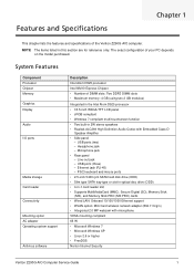
Left and Rear Views Item 1 2 3 4 5 6 7 8 9 10 11 12 13 Component Ventilation slots Mounting holes for wall mount option Optical disc drive (ODD) Kensington lock slot Slot for optional VGA out port Slot for optional serial port Computer stand Power jack Ethernet port (RJ-45) USB ports PS/2 mouse port PS/2 keyboard port Line-out jack Veriton Z290G AIO Computer Service Guide 5
Left and Rear Views Item 1 2 3 4 5 6 7 8 9 10 11 12 13 Component Ventilation slots Mounting holes for wall mount option Optical disc drive (ODD) Kensington lock slot Slot for optional VGA out port Slot for optional serial port Computer stand Power jack Ethernet port (RJ-45) USB ports PS/2 mouse port PS/2 keyboard port Line-out jack Veriton Z290G AIO Computer Service Guide 5
Service Guide
Page 15
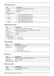
... Blu-ray Disc combo drive option Slim type, tray type or slot-in 12.7 mm SATA • HLDS GT31N • PLDS DS-8A4SH Card Reader Item Controller Supported cards Specification Realtek RTS5159 Card Reader • MultiMediaCard (MMC) • Secure Digital (SD) • Memory Stick (MS) • Memory Stick PRO (MS PRO) cards Ethernet Item Controller LAN protocol LAN connector type Specification Realtek RTL8111DL Gigabit Ethernet controller 10/100/1000 Mbps RJ-45 Wireless LAN Item Model Form factor Specification Lite-On...
... Blu-ray Disc combo drive option Slim type, tray type or slot-in 12.7 mm SATA • HLDS GT31N • PLDS DS-8A4SH Card Reader Item Controller Supported cards Specification Realtek RTS5159 Card Reader • MultiMediaCard (MMC) • Secure Digital (SD) • Memory Stick (MS) • Memory Stick PRO (MS PRO) cards Ethernet Item Controller LAN protocol LAN connector type Specification Realtek RTL8111DL Gigabit Ethernet controller 10/100/1000 Mbps RJ-45 Wireless LAN Item Model Form factor Specification Lite-On...
Service Guide
Page 17
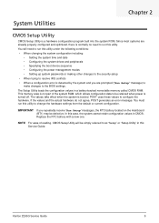
...; Specifying the boot device sequence • Configuring the power management modes • Setting up system passwords or making other changes to the security setup • When trying to the BIOS settings. IMPORTANT If you are already properly configured and optimized, there is normally no need to change the hardware settings from the default or current configuration. Veriton Z290G Service Guide 9 In this case, the system cannot retain configuration values in a battery-backed nonvolatile memory called CMOS RAM. NOTE For...
...; Specifying the boot device sequence • Configuring the power management modes • Setting up system passwords or making other changes to the security setup • When trying to the BIOS settings. IMPORTANT If you are already properly configured and optimized, there is normally no need to change the hardware settings from the default or current configuration. Veriton Z290G Service Guide 9 In this case, the system cannot retain configuration values in a battery-backed nonvolatile memory called CMOS RAM. NOTE For...
Service Guide
Page 22
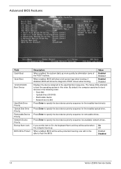
... disabled, BIOS will show the diagnostic POST screen when booting. The Setup Utility attempts to specify the boot device priority sequence for the installed hard drive(s). Press Enter to boot the operating system in the following order: • Hard disk • Optical drive (CD/DVD) • Removable device • Network boot (LAN) Press Enter to On, the keyboard Num Lock key will not be elimination some of the POST routines. On Off Enabled Disabled 14 Veriton Z290G Service Guide Advanced BIOS Features Field Quick Boot...
... disabled, BIOS will show the diagnostic POST screen when booting. The Setup Utility attempts to specify the boot device priority sequence for the installed hard drive(s). Press Enter to boot the operating system in the following order: • Hard disk • Optical drive (CD/DVD) • Removable device • Network boot (LAN) Press Enter to On, the keyboard Num Lock key will not be elimination some of the POST routines. On Off Enabled Disabled 14 Veriton Z290G Service Guide Advanced BIOS Features Field Quick Boot...
Service Guide
Page 28
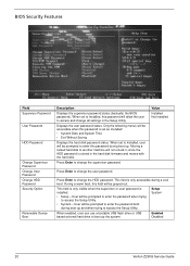
... Setup Utility. Setup System When enabled, user can use a bootable USB flash drive or USB based external hard drive to boot up and when trying to access and change the HDD password. BIOS Security Features Field Supervisor Password User Password HDD Password Change Supervisor Password Change User Password Change HDD Password Security Option Removable Device Boot Description Displays the supervisor password status (basically, the BIOS password). Enabled Disabled 20 Veriton Z290G Service Guide Displays the user password status. Moving a locked hard disk to another machine will...
... Setup Utility. Setup System When enabled, user can use a bootable USB flash drive or USB based external hard drive to boot up and when trying to access and change the HDD password. BIOS Security Features Field Supervisor Password User Password HDD Password Change Supervisor Password Change User Password Change HDD Password Security Option Removable Device Boot Description Displays the supervisor password status (basically, the BIOS password). Enabled Disabled 20 Veriton Z290G Service Guide Displays the user password status. Moving a locked hard disk to another machine will...
Service Guide
Page 33
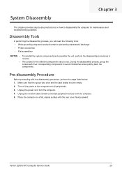
... for maintenance and troubleshooting purposes. Make sure that the optical disc drive and the card reader slot are empty. 2. Unplug the network cable and all peripherals. 3. Veriton Z290G AIO Computer Service Guide 25 Place the computer on how to the computer and all connected peripheral devices from the computer. 4. Pre-disassembly Procedure Before proceeding with the rear cover facing upward. Unplug the power cord from the computer. 5. Turn off the power to disassemble...
... for maintenance and troubleshooting purposes. Make sure that the optical disc drive and the card reader slot are empty. 2. Unplug the network cable and all peripherals. 3. Veriton Z290G AIO Computer Service Guide 25 Place the computer on how to the computer and all connected peripheral devices from the computer. 4. Pre-disassembly Procedure Before proceeding with the rear cover facing upward. Unplug the power cord from the computer. 5. Turn off the power to disassemble...
Service Guide
Page 56
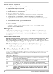
... a LED display. Verify that flat mode is enabled. 48 Veriton Z290G AIO Computer Service Guide Verify that the processor, memory module(s), and expansion board(s) are Acer-qualified and supported. 10. Do additional chipset initialization. Verify that all checkpoints generated by the BIOS requires a checkpoint card, also referred to indicate the task the system is done including RTC and keyboard controller. Verify that may change due to the installed drives...
... a LED display. Verify that flat mode is enabled. 48 Veriton Z290G AIO Computer Service Guide Verify that the processor, memory module(s), and expansion board(s) are Acer-qualified and supported. 10. Do additional chipset initialization. Verify that all checkpoints generated by the BIOS requires a checkpoint card, also referred to indicate the task the system is done including RTC and keyboard controller. Verify that may change due to the installed drives...
Service Guide
Page 58
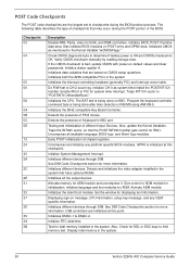
Initialized CMOS as system timer.Install the POSTINT1Ch handler. Initialize status register A. Do R/W test to determine if battery power is OK and CMOS checksum is OK. Program the keyboard controller command byte is bad, update CMOS with power-on default values and clear passwords. Initializes the 8042 compatible Key Board Controller. Detects the presence of PS/2 mouse. Initializes different devices through DIM. Activate ADM module. Initializes the silent boot module. Displaying sign...
Initialized CMOS as system timer.Install the POSTINT1Ch handler. Initialize status register A. Do R/W test to determine if battery power is OK and CMOS checksum is OK. Program the keyboard controller command byte is bad, update CMOS with power-on default values and clear passwords. Initializes the 8042 compatible Key Board Controller. Detects the presence of PS/2 mouse. Initializes different devices through DIM. Activate ADM module. Initializes the silent boot module. Displaying sign...
Service Guide
Page 59
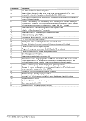
... CPU, ... Display errors to the user and gets the user response for different BIOS modules. Execute BIOS setup if needed . Program the peripheral parameters. Check boot password if installed. Takes care of implementation that needs an adjustment in NVRam. Display boot option popup menu. Deinitializes the ADM module. Save system context for IPL detection. Disables the system configuration display if needed / requested. Initialize runtime language module. Displays the system configuration screen if enabled. Programming the memory...
... CPU, ... Display errors to the user and gets the user response for different BIOS modules. Execute BIOS setup if needed . Program the peripheral parameters. Check boot password if installed. Takes care of implementation that needs an adjustment in NVRam. Display boot option popup menu. Deinitializes the ADM module. Save system context for IPL detection. Disables the system configuration display if needed / requested. Initialize runtime language module. Displays the system configuration screen if enabled. Programming the memory...
Service Guide
Page 60
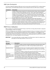
... error is detected during BIOS POST to properly control the mainboard's Gate A20 function, which controls access of memory has occurred, and the ECC memory algorithm cannot correct it. In some cases an error message may occur from faulty memory modules. Follow the instructions on systems using ECC enabled memory modules. This may indicate a problem with a device configuration. The base memory (memory below 1MB) size that you press the Enter key...
... error is detected during BIOS POST to properly control the mainboard's Gate A20 function, which controls access of memory has occurred, and the ECC memory algorithm cannot correct it. In some cases an error message may occur from faulty memory modules. Follow the instructions on systems using ECC enabled memory modules. This may indicate a problem with a device configuration. The base memory (memory below 1MB) size that you press the Enter key...
Service Guide
Page 63
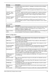
... controller. This is enabled in POST due to replace the hard disk. In this case, the BIOS must be displayed if Virus Detection is a fatal error, often indication a problem with system hardware. error reporting standard. This message will only be updated to the CPU. BIOS could not find or load the CPU Microcode Update to include the Microcode Update for system configuration in AMIBIOS setup. This message appears when the FLASH part...
... controller. This is enabled in POST due to replace the hard disk. In this case, the BIOS must be displayed if Virus Detection is a fatal error, often indication a problem with system hardware. error reporting standard. This message will only be updated to the CPU. BIOS could not find or load the CPU Microcode Update to include the Microcode Update for system configuration in AMIBIOS setup. This message appears when the FLASH part...
Service Guide
Page 65
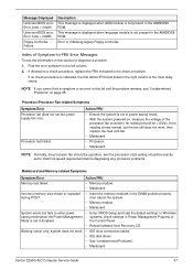
... drive connection/cables • IDE disk drives • See "Undetermined Problems". • Mainboard Veriton Z290G AIO Computer Service Guide 57 Blinking cursor only; system does not work , then replace the heat sink fan. • Mainboard • Processor • Mainboard NOTE Normally, the processor fan should be operative, and the processor clock setting should be exactly set to enter power • Enter CMOS Setup and load the default settings. NOTE If you cannot find a symptom or an error in...
... drive connection/cables • IDE disk drives • See "Undetermined Problems". • Mainboard Veriton Z290G AIO Computer Service Guide 57 Blinking cursor only; system does not work , then replace the heat sink fan. • Mainboard • Processor • Mainboard NOTE Normally, the processor fan should be operative, and the processor clock setting should be exactly set to enter power • Enter CMOS Setup and load the default settings. NOTE If you cannot find a symptom or an error in...
Service Guide
Page 66
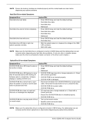
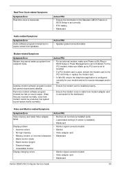
....) Optical Disc Drive-related Symptoms Symptom/Error Action/FRU CD/DVD-ROM drive LED doesn't come on , measure the voltage of the HDD LED connector. • HDD LED cable NOTE Make sure the hard disk drive is configured correctly in CMOS Setup, the cable/jumper are set correctly before diagnosing any hard disk drive problems. (If only one drive is installed, please make sure the drive is connected to unload the disc. • CD/DVD-ROM drive power cable • CD/DVD-ROM drive CD/DVD-ROM drive does not read and there are no sound...
....) Optical Disc Drive-related Symptoms Symptom/Error Action/FRU CD/DVD-ROM drive LED doesn't come on , measure the voltage of the HDD LED connector. • HDD LED cable NOTE Make sure the hard disk drive is configured correctly in CMOS Setup, the cable/jumper are set correctly before diagnosing any hard disk drive problems. (If only one drive is installed, please make sure the drive is connected to unload the disc. • CD/DVD-ROM drive power cable • CD/DVD-ROM drive CD/DVD-ROM drive does not read and there are no sound...
Service Guide
Page 67
... in BIOS Setup or Power Management is set correctly. • RTC battery • Mainboard Audio-related Symptoms Symptom/Error Audio software program invoked but no sound output. (Data files are received normally; voice from suspend mode. • For an external modem, make sure Wake up system from modem cannot be produced, but has no sound comes from modem adapter card is readable). • Mainboard • Monitor signal connection/cable • Monitor • Video adapter card...
... in BIOS Setup or Power Management is set correctly. • RTC battery • Mainboard Audio-related Symptoms Symptom/Error Audio software program invoked but no sound output. (Data files are received normally; voice from suspend mode. • For an external modem, make sure Wake up system from modem cannot be produced, but has no sound comes from modem adapter card is readable). • Mainboard • Monitor signal connection/cable • Monitor • Video adapter card...
Service Guide
Page 103
... menu 15 Advanced Configuration Power Interface specifications 2 wake-up options 17 antivirus software 1 audio headphone jack 4 line-out jack 5 microphone jack 4 specifications 8 troubleshooting 59 B BIOS checkpoints 48 clear CMOS 62 crisis recovery disk 61 recovery 61 specifications 6 system passwords 20 version 12 BIOS Security Features menu 20 block diagram 63 boot block checkpoints 48 execute 61 boot sequence 14 brightness control keys 4 C card reader location 4 specifications 7 checkpoints boot block 48 DIM 52 overview 48 POST 50 CMOS clear 62 CMOS Setup Utility access 10 Advanced BIOS...
... menu 15 Advanced Configuration Power Interface specifications 2 wake-up options 17 antivirus software 1 audio headphone jack 4 line-out jack 5 microphone jack 4 specifications 8 troubleshooting 59 B BIOS checkpoints 48 clear CMOS 62 crisis recovery disk 61 recovery 61 specifications 6 system passwords 20 version 12 BIOS Security Features menu 20 block diagram 63 boot block checkpoints 48 execute 61 boot sequence 14 brightness control keys 4 C card reader location 4 specifications 7 checkpoints boot block 48 DIM 52 overview 48 POST 50 CMOS clear 62 CMOS Setup Utility access 10 Advanced BIOS...
Service Guide
Page 104
... view 68 part number updates 67 G graphics controller 1 H hard disk drive access password 20 bracket, part number 71 part number 70 remove 37 SATA connectors 64 specifications 7 troubleshooting 58 hardware configuration utility 9 exploded view 68 FRU list 67 information display 12 model configurations 80 specifications 6 status monitoring 18 troubleshooting 47 HDD, see hard disk drive 1 headphone jack 4 heat sink part number 70 remove 40 humidity 2 I I/O ports listing 1 location 5 Integrated Peripherals menu 16 inverter board cable, part number 72 cover, part number 72 part number 69 remove 33...
... view 68 part number updates 67 G graphics controller 1 H hard disk drive access password 20 bracket, part number 71 part number 70 remove 37 SATA connectors 64 specifications 7 troubleshooting 58 hardware configuration utility 9 exploded view 68 FRU list 67 information display 12 model configurations 80 specifications 6 status monitoring 18 troubleshooting 47 HDD, see hard disk drive 1 headphone jack 4 heat sink part number 70 remove 40 humidity 2 I I/O ports listing 1 location 5 Integrated Peripherals menu 16 inverter board cable, part number 72 cover, part number 72 part number 69 remove 33...

Service Guide
Page 105
... menu 12 PS/2 keyboard port 5 PS/2 mouse port 5 R rear cover, part number 71 reset button 4 Return Merchandise Authorization 67 RMA, see Return Merchandise Authorization 67 RTC battery BIOS error 9 location 64 RTC clock RTC battery 64 troubleshooting 59 S Save & Exit Setup menu 24 security features 2 serial port cable, part number 72 slot location 5 side bars part number 71 remove 27 speakers location 3 part number 71 remove 43 specifications AC adapter 8 antivirus 1 audio 8 card reader 7 display 8 Ethernet controller 7 hard disk drive 7 memory 6 optical disc drive 7 processor 6 system BIOS...
... menu 12 PS/2 keyboard port 5 PS/2 mouse port 5 R rear cover, part number 71 reset button 4 Return Merchandise Authorization 67 RMA, see Return Merchandise Authorization 67 RTC battery BIOS error 9 location 64 RTC clock RTC battery 64 troubleshooting 59 S Save & Exit Setup menu 24 security features 2 serial port cable, part number 72 slot location 5 side bars part number 71 remove 27 speakers location 3 part number 71 remove 43 specifications AC adapter 8 antivirus 1 audio 8 card reader 7 display 8 Ethernet controller 7 hard disk drive 7 memory 6 optical disc drive 7 processor 6 system BIOS...
Service Guide
Page 106
... 5 rear view 5 right view 4 T temperature monitoring 18 operating range 2 touchscreen assembly, part number 70 by model 8 control board, part number 69 control cable, part number 72 panel film, part number 70 specification 1 troubleshooting BIOS checkpoints 48 BIOS recovery 61 clearing CMOS 62 component failure 57 hardware diagnostic procedure 47 online support information 93 POST error indicators 52 U USB ports bootable device 16 legacy device 16 right 4, 5 user password 20 V VESA mounting 1 VGA out port 5 W wall mount option 5 webcam cable, part number 72 cable, remove 42 location 3 module...
... 5 rear view 5 right view 4 T temperature monitoring 18 operating range 2 touchscreen assembly, part number 70 by model 8 control board, part number 69 control cable, part number 72 panel film, part number 70 specification 1 troubleshooting BIOS checkpoints 48 BIOS recovery 61 clearing CMOS 62 component failure 57 hardware diagnostic procedure 47 online support information 93 POST error indicators 52 U USB ports bootable device 16 legacy device 16 right 4, 5 user password 20 V VESA mounting 1 VGA out port 5 W wall mount option 5 webcam cable, part number 72 cable, remove 42 location 3 module...


