Service Guide
Page 7
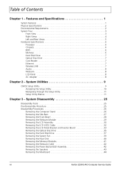
... Setup Utility 10 Navigating through the Setup Utility 11 Setup Utility Menus 11 Chapter 3 - System Disassembly 25 Disassembly Tools 25 Pre-disassembly Procedure 25 Disassembly Procedures 26 Removing the Computer Stand 26 Removing the Side Bars 27 Removing the Front Bezel 28 ...Modules 41 Removing the Webcam Cable 42 Removing the Power Button/LED Assembly 42 Removing the Speakers 43 Removing the Mainboard 44 vii Veriton Z290G AIO Computer Service Guide Table of Contents Chapter 1 - Features and Specifications 1 System Features 1 Physical Specifications 2 Environmental ...
... Setup Utility 10 Navigating through the Setup Utility 11 Setup Utility Menus 11 Chapter 3 - System Disassembly 25 Disassembly Tools 25 Pre-disassembly Procedure 25 Disassembly Procedures 26 Removing the Computer Stand 26 Removing the Side Bars 27 Removing the Front Bezel 28 ...Modules 41 Removing the Webcam Cable 42 Removing the Power Button/LED Assembly 42 Removing the Speakers 43 Removing the Mainboard 44 vii Veriton Z290G AIO Computer Service Guide Table of Contents Chapter 1 - Features and Specifications 1 System Features 1 Physical Specifications 2 Environmental ...
Service Guide
Page 33
...8226; The screws for maintenance and troubleshooting purposes. During the disassembly process, group the screws with their corresponding components to the computer and all connected peripheral devices from the computer. 4. Veriton Z290G AIO Computer Service Guide 25 Unplug the network cable and ...all peripherals. 3. Turn off the power to avoid mismatches when putting back the components. System Disassembly Chapter 3 This chapter provides step-by-step...
...8226; The screws for maintenance and troubleshooting purposes. During the disassembly process, group the screws with their corresponding components to the computer and all connected peripheral devices from the computer. 4. Veriton Z290G AIO Computer Service Guide 25 Unplug the network cable and ...all peripherals. 3. Turn off the power to avoid mismatches when putting back the components. System Disassembly Chapter 3 This chapter provides step-by-step...

Service Guide
Page 34
Quantity 3 Color Chrome Torque 4.0 +/- 0.3 kgf-cm Part Number 86.00J97.668 26 Veriton Z290G AIO Computer Service Guide Remove the screws securing the computer stand. Remove the plastic shell covering the computer stand screws. 3. Disassembly Procedures Removing the Computer Stand 1. Perform the "Pre-disassembly Procedure" on page 25. 2.
Quantity 3 Color Chrome Torque 4.0 +/- 0.3 kgf-cm Part Number 86.00J97.668 26 Veriton Z290G AIO Computer Service Guide Remove the screws securing the computer stand. Remove the plastic shell covering the computer stand screws. 3. Disassembly Procedures Removing the Computer Stand 1. Perform the "Pre-disassembly Procedure" on page 25. 2.

Service Guide
Page 35
Perform the "Pre-disassembly Procedure" on page 25. 2. Remove the screws securing the side bars. Removing the Side Bars 1. Remove the computer stand. Quantity 2 Color Black Torque 4.0 +/- 0.3 kgf-cm Part Number 86.ZA324.8R0 Veriton Z290G AIO Computer Service Guide 27 4.
Perform the "Pre-disassembly Procedure" on page 25. 2. Remove the screws securing the side bars. Removing the Side Bars 1. Remove the computer stand. Quantity 2 Color Black Torque 4.0 +/- 0.3 kgf-cm Part Number 86.ZA324.8R0 Veriton Z290G AIO Computer Service Guide 27 4.
Service Guide
Page 36
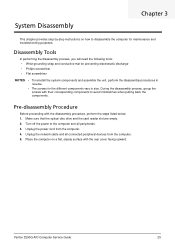
Remove the side bars by following the procedure described on page 25. 2. Removing the Front Bezel 1. Use a flat screwdriver to pry off the front bezel from the chassis, then detach the bars. Perform the "Pre-disassembly Procedure" on the previous section. 3. Slide the side bars downward to access the webcam cable. 28 Veriton Z290G AIO Computer Service Guide Detach the front bezel from the rear cover and turn it over to disengage the bars' inner tabs from the rear cover. 4. 3.
Remove the side bars by following the procedure described on page 25. 2. Removing the Front Bezel 1. Use a flat screwdriver to pry off the front bezel from the chassis, then detach the bars. Perform the "Pre-disassembly Procedure" on the previous section. 3. Slide the side bars downward to access the webcam cable. 28 Veriton Z290G AIO Computer Service Guide Detach the front bezel from the rear cover and turn it over to disengage the bars' inner tabs from the rear cover. 4. 3.
Service Guide
Page 103
... Setup Utility access 10 Advanced BIOS Features menu 14 Advanced Chipset Features menu 15 BIOS Security Features menu 20 Exit Without Saving 24 Veriton Z290G AIO Computer Service Guide Index Frequency/Voltage Control menu 19 Integrated Peripherals menu 16 Load Default Settings 23 navigation keys 11 overview... stand location 5 part number 71 remove 26 computer stand hinge cover, part number 71 connectivity Ethernet 7 WLAN 7 D DIM checkpoints 52 disassembly procedures computer stand 26 front bezel 28 guidelines 67 hard disk drive 37 heat sink 40 inverter board 33 LCD assembly 30 LCD LVDS cable...
... Setup Utility access 10 Advanced BIOS Features menu 14 Advanced Chipset Features menu 15 BIOS Security Features menu 20 Exit Without Saving 24 Veriton Z290G AIO Computer Service Guide Index Frequency/Voltage Control menu 19 Integrated Peripherals menu 16 Load Default Settings 23 navigation keys 11 overview... stand location 5 part number 71 remove 26 computer stand hinge cover, part number 71 connectivity Ethernet 7 WLAN 7 D DIM checkpoints 52 disassembly procedures computer stand 26 front bezel 28 guidelines 67 hard disk drive 37 heat sink 40 inverter board 33 LCD assembly 30 LCD LVDS cable...


