Quick Start Guide
Page 1
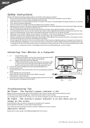
... avoid electric shock, never touch the inside of the monitor and connect the other end to a Computer 1. 1-1 Connect Video Cable a. If you put the monitor in CD-ROM packaged with this test. This sequence is on and functioning properly. Connect the VGA video cable to diagnose the problem. 1-1 1-2 3 2 32 1-2 1 -1 Troubleshooting Tips No Power - shooting section to the computer. 1-2 Digital Cable (Only Dual-Input Model) a. LCD Monitor Quick Setup Guide Do not allow anything...
... avoid electric shock, never touch the inside of the monitor and connect the other end to a Computer 1. 1-1 Connect Video Cable a. If you put the monitor in CD-ROM packaged with this test. This sequence is on and functioning properly. Connect the VGA video cable to diagnose the problem. 1-1 1-2 3 2 32 1-2 1 -1 Troubleshooting Tips No Power - shooting section to the computer. 1-2 Digital Cable (Only Dual-Input Model) a. LCD Monitor Quick Setup Guide Do not allow anything...
Quick Start Guide
Page 2
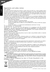
... may be determined by turning the device off your waste equipment at the time of the FCC rules. LCD Monitor Quick Setup Guide This device generates, uses, and can radiate radio frequency energy and, if not installed and used in a manner that interference will help . Caution Changes or modifications not expressly approved by the manufacturer could void the user authority, which can drop...
... may be determined by turning the device off your waste equipment at the time of the FCC rules. LCD Monitor Quick Setup Guide This device generates, uses, and can radiate radio frequency energy and, if not installed and used in a manner that interference will help . Caution Changes or modifications not expressly approved by the manufacturer could void the user authority, which can drop...
User Manual
Page 1
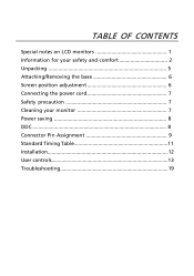
TABLE OF CONTENTS Special notes on LCD monitors 1 Information for your safety and comfort 2 Unpacking 5 Attaching/Removing the base 6 Screen position adjustment 6 Connecting the power cord 7 Safety precaution 7 Cleaning your monitor 7 Power saving 8 DDC 8 Connector Pin Assignment 9 Standard Timing Table 11 Installation 12 User controls 13 Troubleshooting 19
TABLE OF CONTENTS Special notes on LCD monitors 1 Information for your safety and comfort 2 Unpacking 5 Attaching/Removing the base 6 Screen position adjustment 6 Connecting the power cord 7 Safety precaution 7 Cleaning your monitor 7 Power saving 8 DDC 8 Connector Pin Assignment 9 Standard Timing Table 11 Installation 12 User controls 13 Troubleshooting 19
User Manual
Page 2
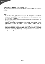
.... Turn off the Power Switch for hours. SPECIAL NOTES ON LCD MONITORS The following symptoms are normal with LCD monitor and do not indicate a problem. EN-1 In this case, the screen is displayed for hours. NOTES • Due to make sure the flicker disappears. • You may flicker during initial use . • The LCD screen has effective pixels of the fluorescent light, the screen may find slightly uneven brightness on...
.... Turn off the Power Switch for hours. SPECIAL NOTES ON LCD MONITORS The following symptoms are normal with LCD monitor and do not indicate a problem. EN-1 In this case, the screen is displayed for hours. NOTES • Due to make sure the flicker disappears. • You may flicker during initial use . • The LCD screen has effective pixels of the fluorescent light, the screen may find slightly uneven brightness on...

User Manual
Page 3
...,to block out noisy surroundings. • Turn the volume down if you can hear it could result in installation unless proper ventilation is easily accessible and located as close to the equipment operator as they may touch dangerous voltage points or short-out parts that the power outlet you plug the power cord into this product through cabinet slots...
...,to block out noisy surroundings. • Turn the volume down if you can hear it could result in installation unless proper ventilation is easily accessible and located as close to the equipment operator as they may touch dangerous voltage points or short-out parts that the power outlet you plug the power cord into this product through cabinet slots...
User Manual
Page 4
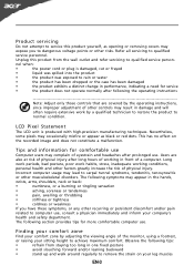
... backward • stand up and walk around regularly to qualified service personnel. Observe the following the operating instructions Note: Adjust only those controls that are also at risk of physical injury. Refer all servicing to remove the strain on the recorded image and does not constitute a malfunction. Unplug this product yourself, as black or red dots. Nevertheless, some pixels may lead...
... backward • stand up and walk around regularly to qualified service personnel. Observe the following the operating instructions Note: Adjust only those controls that are also at risk of physical injury. Refer all servicing to remove the strain on the recorded image and does not constitute a malfunction. Unplug this product yourself, as black or red dots. Nevertheless, some pixels may lead...
User Manual
Page 5
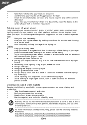
... your documents, place the display at bright light sources, such as open windows, for only short periods, take short rests to relax your neck and shoulders • avoid tensing your muscles or shrugging your shoulders • install the external display, keyboard and mouse properly and within comfort able reach • if you view your monitor more than the top edge...
... your documents, place the display at bright light sources, such as open windows, for only short periods, take short rests to relax your neck and shoulders • avoid tensing your muscles or shrugging your shoulders • install the external display, keyboard and mouse properly and within comfort able reach • if you view your monitor more than the top edge...
User Manual
Page 6
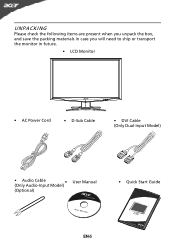
UNPACKING Please check the following items are present when you unpack the box, and save the packing materials in case you will need to ship or transport the monitor in future. • LCD Monitor • AC Power Cord • D-Sub Cable • DVI Cable (Only Dual-Input Model) • Audio Cable (Only Audio-Input Model) • (Optional) User Manual • Quick Start Guide EN-5
UNPACKING Please check the following items are present when you unpack the box, and save the packing materials in case you will need to ship or transport the monitor in future. • LCD Monitor • AC Power Cord • D-Sub Cable • DVI Cable (Only Dual-Input Model) • Audio Cable (Only Audio-Input Model) • (Optional) User Manual • Quick Start Guide EN-5
User Manual
Page 7
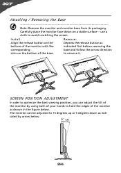
EN-6 Attaching / Removing the Base Note: Remove the monitor and monitor base from its packaging. use a cloth to remove it. SCREEN POSITION ADJUSTMENT In oder to optimize the best viewing position, you can be adjusted to hold the edges of the monitor as bottom of the monitor with the indicated first before removing the corresponding base and follow the arrow direction slots on the bottom of the base. to avoid scratching the...
EN-6 Attaching / Removing the Base Note: Remove the monitor and monitor base from its packaging. use a cloth to remove it. SCREEN POSITION ADJUSTMENT In oder to optimize the best viewing position, you can be adjusted to hold the edges of the monitor as bottom of the monitor with the indicated first before removing the corresponding base and follow the arrow direction slots on the bottom of the base. to avoid scratching the...
User Manual
Page 8
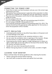
... be installed. No user-adjustment is required. • Plug one end of the power cord to the AC Inlet, plug another end to a proper AC outlet. • For unit using at 120 V AC: Use a UL Listed Cord Set, Type SVT wire and plug rated 10 A/125 V. • For unit using at 220/240 V AC (outside of U.S.): Use a Cord Set consisting of the monitor. CONNECTING THE POWER CORD • Check first to make sure...
... be installed. No user-adjustment is required. • Plug one end of the power cord to the AC Inlet, plug another end to a proper AC outlet. • For unit using at 120 V AC: Use a UL Listed Cord Set, Type SVT wire and plug rated 10 A/125 V. • For unit using at 220/240 V AC (outside of U.S.): Use a Cord Set consisting of the monitor. CONNECTING THE POWER CORD • Check first to make sure...
User Manual
Page 9
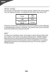
... the display controller, as indicated by the control signal from Active OFF state back to Plug and Play with your system if your installation easier, the monitor is able to ON state is around 3 seconds. The DDC (Display Data Channel) is activated. EN-8 DDC To make your system also supports DDC protocol. The monitor supports DDC2B standard. State ON Power Saving Mode LED Light Blue Orange The power saving states...
... the display controller, as indicated by the control signal from Active OFF state back to Plug and Play with your system if your installation easier, the monitor is able to ON state is around 3 seconds. The DDC (Display Data Channel) is activated. EN-8 DDC To make your system also supports DDC protocol. The monitor supports DDC2B standard. State ON Power Saving Mode LED Light Blue Orange The power saving states...
User Manual
Page 10
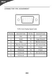
CONNECTOR PIN ASSIGNMENT 5 1 10 6 15 11 15-Pin Color Display Signal Cable PIN NO. 1. 2. 3. 4. 5. 6. 7. 8. DESCRIPTION +5V Logic Ground Monitor Ground DDC-Serial Data H-Sync V-Sync DDC-Serial Clock EN-9 DESCRIPTION Red Green Blue Monitor Ground Self Test R-Ground G-Ground B-Ground PIN NO. 9. 10. 11. 12. 13. 14. 15.
CONNECTOR PIN ASSIGNMENT 5 1 10 6 15 11 15-Pin Color Display Signal Cable PIN NO. 1. 2. 3. 4. 5. 6. 7. 8. DESCRIPTION +5V Logic Ground Monitor Ground DDC-Serial Data H-Sync V-Sync DDC-Serial Clock EN-9 DESCRIPTION Red Green Blue Monitor Ground Self Test R-Ground G-Ground B-Ground PIN NO. 9. 10. 11. 12. 13. 14. 15.
User Manual
Page 11
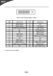
TMDS Data 2/4 Shield 15. 4. DDC Data 19. 8. TMDS Data 1/3 Shield 23. 12. TMDS Data2+ 14. 3. TMDS Data1+ 22. 11. TMDS Data1- 21. 10. NC 24. NC 17. 6. NC 16. 5. NC 20. 9. Meaning NC +5V Power Logic Ground Hot Plug Detect TMDS Data0TMDS Data0+ TMDS Data 0/5 Shield NC NC TMDS Clock Shield TMDS Clock+ DDC TMDS Clock- * only for certain models EN-10 DDC Clock 18. 7. 24-Pin Color Display Signal Cable* PIN Meaning PIN 1. TMDS Data2- 13. 2.
TMDS Data 2/4 Shield 15. 4. DDC Data 19. 8. TMDS Data 1/3 Shield 23. 12. TMDS Data2+ 14. 3. TMDS Data1+ 22. 11. TMDS Data1- 21. 10. NC 24. NC 17. 6. NC 16. 5. NC 20. 9. Meaning NC +5V Power Logic Ground Hot Plug Detect TMDS Data0TMDS Data0+ TMDS Data 0/5 Shield NC NC TMDS Clock Shield TMDS Clock+ DDC TMDS Clock- * only for certain models EN-10 DDC Clock 18. 7. 24-Pin Color Display Signal Cable* PIN Meaning PIN 1. TMDS Data2- 13. 2.
User Manual
Page 13
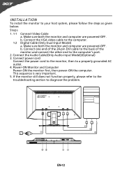
...-pin DVI cable to the back of the monitor and connect the other end to diagnose the problem. 1-1 1-2 3 2 32 1-2 1-1 EN-12 This sequence is very important. 5. If the monitor still does not function properly, please refer to the troubleshooting section to the computer's port. 2. Connect the Audio Cable(Only Audio-Input Model)(Optional) 3. Make sure both the monitor and computer are powered-OFF. Connect the VGA video cable to the computer. 1-2 Digital Cable...
...-pin DVI cable to the back of the monitor and connect the other end to diagnose the problem. 1-1 1-2 3 2 32 1-2 1-1 EN-12 This sequence is very important. 5. If the monitor still does not function properly, please refer to the troubleshooting section to the computer's port. 2. Connect the Audio Cable(Only Audio-Input Model)(Optional) 3. Make sure both the monitor and computer are powered-OFF. Connect the VGA video cable to the computer. 1-2 Digital Cable...
User Manual
Page 14
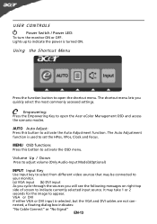
... to open the Acer eColor Management OSD and access the scenario modes. MENU OSD functions Press this button to appear. Volume Up / Down Press to adjust volume (Only Audio-Input Model)(Optional) INPUT Input Key Use Input key to select from different video sources that may take 1 or 2 seconds for the image to activate the Auto Adjustment function. VGA or DVI If either VGA or DVI input is turned ON. AUTO Auto Adjust: Press this botton to indicate currently selected input source. The Auto Adjustment...
... to open the Acer eColor Management OSD and access the scenario modes. MENU OSD functions Press this button to appear. Volume Up / Down Press to adjust volume (Only Audio-Input Model)(Optional) INPUT Input Key Use Input key to select from different video sources that may take 1 or 2 seconds for the image to activate the Auto Adjustment function. VGA or DVI If either VGA or DVI input is turned ON. AUTO Auto Adjust: Press this botton to indicate currently selected input source. The Auto Adjustment...
User Manual
Page 15
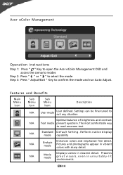
... Menu icon Sub Menu icon Sub Menu item Description N/A User mode User defined. Settings can be fine-tuned to confirm the mode and run Auto Adjust. Acer eColor Management Operation instructions Step 1: Press " " Key to open the Acer eColor Management OSD and access the scenario modes Step 2: Press " " or " " to select the mode Step 3: Press " Adjust/Exit " Key to suit any situation Optimal balance of brightness and contrast N/A Text mode prevent eyestrain. Pictures...
... Menu icon Sub Menu icon Sub Menu item Description N/A User mode User defined. Settings can be fine-tuned to confirm the mode and run Auto Adjust. Acer eColor Management Operation instructions Step 1: Press " " Key to open the Acer eColor Management OSD and access the scenario modes Step 2: Press " " or " " to select the mode Step 3: Press " Adjust/Exit " Key to suit any situation Optimal balance of brightness and contrast N/A Text mode prevent eyestrain. Pictures...
User Manual
Page 16
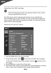
Actual product specifications may vary. For advanced settings, please refer to following content is for adjusting the settings of your LCD Monitor. You can use the OSD to open the OSD. EN-15 Press the MENU key to adjust the picture quality, OSD Timeout and general settings. The OSD can be used to adjust the current Brightness, Contrast, Colour Temp, Auto Config and other image-related qualities. Then navigate to the picture element you...
Actual product specifications may vary. For advanced settings, please refer to following content is for adjusting the settings of your LCD Monitor. You can use the OSD to open the OSD. EN-15 Press the MENU key to adjust the picture quality, OSD Timeout and general settings. The OSD can be used to adjust the current Brightness, Contrast, Colour Temp, Auto Config and other image-related qualities. Then navigate to the picture element you...
User Manual
Page 20
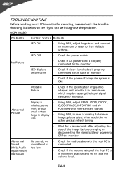
... specification of graphics adapter and monitor is ON. shift, or too POSITION with the host PC is connected. · Check if the volume setup of the host PC is too low · Check the audio cable with non-standard signals. No Picture · Check if AC power cord is · Using OSD, adjust RESOLUTION, CLOCK, missing, center CLOCK-PHASE, H-POSITION and V- EN-19 LED OFF · Check the power switch. Abnormal Picture Display is properly connected to their default settings. TROUBLESHOOTING...
... specification of graphics adapter and monitor is ON. shift, or too POSITION with the host PC is connected. · Check if the volume setup of the host PC is too low · Check the audio cable with non-standard signals. No Picture · Check if AC power cord is · Using OSD, adjust RESOLUTION, CLOCK, missing, center CLOCK-PHASE, H-POSITION and V- EN-19 LED OFF · Check the power switch. Abnormal Picture Display is properly connected to their default settings. TROUBLESHOOTING...
User Manual
Page 21
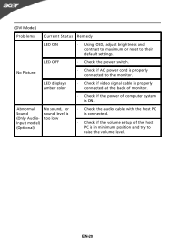
... model) (Optional) No sound, or sound level is too low · Check the audio cable with the host PC is connected. · Check if the volume setup of computer system is ON. EN-20 LED displays amber color · Check if video signal cable is properly connected at the back of monitor. · Check if the power of the host PC is properly connected to their default settings. (DVI Mode) Problems Current Status Remedy LED ON · Using OSD, adjust brightness and contrast...
... model) (Optional) No sound, or sound level is too low · Check the audio cable with the host PC is connected. · Check if the volume setup of computer system is ON. EN-20 LED displays amber color · Check if video signal cable is properly connected at the back of monitor. · Check if the power of the host PC is properly connected to their default settings. (DVI Mode) Problems Current Status Remedy LED ON · Using OSD, adjust brightness and contrast...
User Manual
Page 23
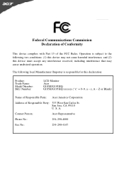
... harmful interference, and (2) this declaration: Product: Trade Name: Model Number: SKU Number: LCD Monitor Acer .G185H/G195HQ .G185H/G195HQ xxxxxx ("x" = 0~9, a ~ z, A ~ Z or Blank) Name of Responsible Party: Acer America Corporation Address of the FCC Rules. Contact Person: Acer Representative Phone No.: 254-298-4000 Fax No.: 254-298...: (1) this device may cause undesired operation. S. San Jose, CA 95110 U. www.acer.com Federal Communications Commission Declaration of Conformity This device complies with Part 15 of Responsible Party: 333 West San Carlos St. A.
... harmful interference, and (2) this declaration: Product: Trade Name: Model Number: SKU Number: LCD Monitor Acer .G185H/G195HQ .G185H/G195HQ xxxxxx ("x" = 0~9, a ~ z, A ~ Z or Blank) Name of Responsible Party: Acer America Corporation Address of the FCC Rules. Contact Person: Acer Representative Phone No.: 254-298-4000 Fax No.: 254-298...: (1) this device may cause undesired operation. S. San Jose, CA 95110 U. www.acer.com Federal Communications Commission Declaration of Conformity This device complies with Part 15 of Responsible Party: 333 West San Carlos St. A.


