
User Manual
Page 9
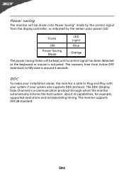
The recovery time from the display controller, as indicated by the control signal from Active OFF state back to Plug and Play with your system if your system also supports DDC protocol. DDC To make your installation easier, ...-8 The DDC (Display Data Channel) is activated. State ON Power Saving Mode LED Light Blue Orange The power saving states will be kept until a control signal has been detected or the keyboard or mouse is a communication protocol through which the monitor automatically informs the host system about its capabilities, for example...
The recovery time from the display controller, as indicated by the control signal from Active OFF state back to Plug and Play with your system if your system also supports DDC protocol. DDC To make your installation easier, ...-8 The DDC (Display Data Channel) is activated. State ON Power Saving Mode LED Light Blue Orange The power saving states will be kept until a control signal has been detected or the keyboard or mouse is a communication protocol through which the monitor automatically informs the host system about its capabilities, for example...
User Manual
Page 10
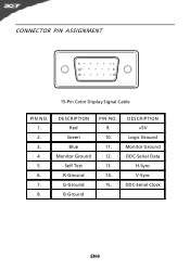
CONNECTOR PIN ASSIGNMENT 5 1 10 6 15 11 15-Pin Color Display Signal Cable PIN NO. 1. 2. 3. 4. 5. 6. 7. 8. DESCRIPTION Red Green Blue Monitor Ground Self Test R-Ground G-Ground B-Ground PIN NO. 9. 10. 11. 12. 13. 14. 15. DESCRIPTION +5V Logic Ground Monitor Ground DDC-Serial Data H-Sync V-Sync DDC-Serial Clock EN-9
CONNECTOR PIN ASSIGNMENT 5 1 10 6 15 11 15-Pin Color Display Signal Cable PIN NO. 1. 2. 3. 4. 5. 6. 7. 8. DESCRIPTION Red Green Blue Monitor Ground Self Test R-Ground G-Ground B-Ground PIN NO. 9. 10. 11. 12. 13. 14. 15. DESCRIPTION +5V Logic Ground Monitor Ground DDC-Serial Data H-Sync V-Sync DDC-Serial Clock EN-9
User Manual
Page 11
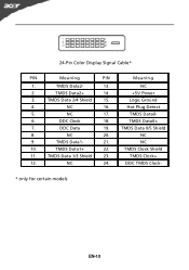
NC 16. 5. TMDS Data 1/3 Shield 23. 12. DDC Clock 18. 7. NC 20. 9. 24-Pin Color Display Signal Cable* PIN Meaning PIN 1. TMDS Data2+ 14. 3. NC 17. 6. DDC Data 19. 8. NC 24. TMDS Data1- 21. 10. Meaning NC +5V Power Logic Ground Hot Plug Detect TMDS Data0TMDS Data0+ TMDS Data 0/5 Shield NC NC TMDS Clock Shield TMDS Clock+ DDC TMDS Clock- * only for certain models EN-10 TMDS Data2- 13. 2. TMDS Data1+ 22. 11. TMDS Data 2/4 Shield 15. 4.
NC 16. 5. TMDS Data 1/3 Shield 23. 12. DDC Clock 18. 7. NC 20. 9. 24-Pin Color Display Signal Cable* PIN Meaning PIN 1. TMDS Data2+ 14. 3. NC 17. 6. DDC Data 19. 8. NC 24. TMDS Data1- 21. 10. Meaning NC +5V Power Logic Ground Hot Plug Detect TMDS Data0TMDS Data0+ TMDS Data 0/5 Shield NC NC TMDS Clock Shield TMDS Clock+ DDC TMDS Clock- * only for certain models EN-10 TMDS Data2- 13. 2. TMDS Data1+ 22. 11. TMDS Data 2/4 Shield 15. 4.
User Manual
Page 14
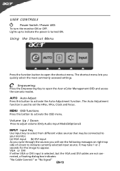
...will see the following messages on right top side of screen to indicate currently selected input source. Empowering: Press the Empowering Key to open the Acer eColor Management OSD and access the scenario modes. VGA or DVI If either VGA or DVI input is turned ON. It may be connected to... used to indicate the power is selected ,but the VGA and DVI cables are not connected, a floating dialog box indicates: "No Cable Connect" or "No Signal" EN-13 USER CONTROLS Power Switch / Power LED: To turn the monitor ON or OFF. Volume Up / Down Press to adjust volume (Only Audio-Input...
...will see the following messages on right top side of screen to indicate currently selected input source. Empowering: Press the Empowering Key to open the Acer eColor Management OSD and access the scenario modes. VGA or DVI If either VGA or DVI input is turned ON. It may be connected to... used to indicate the power is selected ,but the VGA and DVI cables are not connected, a floating dialog box indicates: "No Cable Connect" or "No Signal" EN-13 USER CONTROLS Power Switch / Power LED: To turn the monitor ON or OFF. Volume Up / Down Press to adjust volume (Only Audio-Input...
User Manual
Page 20
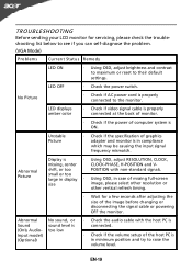
... power cord is ON. Unstable Picture · Check if the specification of graphics adapter and monitor is in compliance which may be causing the input signal frequency mismatch. shift, or too POSITION with the host PC is connected. · Check if the volume setup of the host PC is in ...minimum position and try to the monitor. LED OFF · Check the power switch. LED displays amber color · Check if video signal cable is properly connected at the back of monitor. · Check if the power of computer system is properly connected to raise the volume level...
... power cord is ON. Unstable Picture · Check if the specification of graphics adapter and monitor is in compliance which may be causing the input signal frequency mismatch. shift, or too POSITION with the host PC is connected. · Check if the volume setup of the host PC is in ...minimum position and try to the monitor. LED OFF · Check the power switch. LED displays amber color · Check if video signal cable is properly connected at the back of monitor. · Check if the power of computer system is properly connected to raise the volume level...
User Manual
Page 21
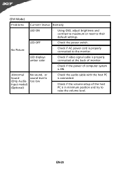
... setup of computer system is in minimum position and try to raise the volume level. EN-20 LED displays amber color · Check if video signal cable is properly connected at the back of monitor. · Check if the power of the host PC is ON. No Picture · Check if...
... setup of computer system is in minimum position and try to raise the volume level. EN-20 LED displays amber color · Check if video signal cable is properly connected at the back of monitor. · Check if the power of the host PC is ON. No Picture · Check if...


