Acer Aspire X1420G Motherboard
View Results Below
Free Acer Aspire X1420G manuals!
Problems with Acer Aspire X1420G?
Ask a Question
Free Acer Aspire X1420G manuals!
Problems with Acer Aspire X1420G?
Ask a Question
Related Manual Pages

Similar Questions

My Acer Aspire Ax3400 Needs A New Cmos Battery Were Is It On The Motherboard
my acer aspire ax3400 needs a new cmos battery were is it on the motherboard
my acer aspire ax3400 needs a new cmos battery were is it on the motherboard
(Posted by powellthomas95 4 years ago)

What Motherboard Is In The Acer Aspire X1420g Desktop
(Posted by bones1jona 9 years ago)

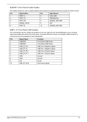
How Many Pin Connectors Does An Acer Aspire X1420g Motherboard Have
(Posted by LujeCa 9 years ago)
My 3600 Motherboard
my 3600 motherboard must be changed.can i find anotheronecompatible?
my 3600 motherboard must be changed.can i find anotheronecompatible?
(Posted by olaerud 10 years ago)

Price Acer Aspire Z5761 Motherboard
Price Acer Aspire z5761 Motherboard
Price Acer Aspire z5761 Motherboard
(Posted by frenzkhy 10 years ago)