Acer Aspire One 531H Netbook Series User Guide
Page 6
...product. Batteries may also explode if damaged. Follow local regulations when disposing of batteries according to : wireless lan (WLAN), Bluetooth and/or 3G. Use only Acer approved batteries, and recharge your battery only with your pocket or purse. Keep them away from the battery, which came bundled with... Acer approved chargers designated for its use any area, and always switch off all wireless or radio transmitting devices when using your device...
...product. Batteries may also explode if damaged. Follow local regulations when disposing of batteries according to : wireless lan (WLAN), Bluetooth and/or 3G. Use only Acer approved batteries, and recharge your battery only with your pocket or purse. Keep them away from the battery, which came bundled with... Acer approved chargers designated for its use any area, and always switch off all wireless or radio transmitting devices when using your device...

Acer Aspire One 531H Netbook Series User Guide
Page 21
.... 2. English 3 Indicators The computer has serveral easy-to-read status indicators. Wireless LAN Indicates the status of Wireless LAN communication. 3G Indicates the status of Bluetooth communication. Icon Function Bluetooth Description Indicates the status of 3G communication. Caps Lock Battery Lights up when Num Lock is activated. Indicates the computer's batttery status. 1.
.... 2. English 3 Indicators The computer has serveral easy-to-read status indicators. Wireless LAN Indicates the status of Wireless LAN communication. 3G Indicates the status of Bluetooth communication. Icon Function Bluetooth Description Indicates the status of 3G communication. Caps Lock Battery Lights up when Num Lock is activated. Indicates the computer's batttery status. 1.
Aspire One AO531h Service Guide
Page 7
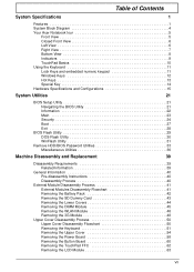
Table of Contents System Specifications 1 Features 1 System Block Diagram 4 Your Acer Notebook tour 5 Front View 5 Closed Front View 6 Left View 6 Right View 7 Bottom View 8 Indicators 9 TouchPad Basics 10 Using the Keyboard 11 Lock Keys and embedded ... Pack 42 Removing the SD Dummy Card 43 Removing the Lower Covers 44 Removing the DIMM Module 45 Removing the WLAN Module 46 Removing the 3G Module 48 Upper Cover Disassembly Process 50 Upper Cover Disassembly Flowchart 50 Removing the Keyboard 51 Removing the Upper Cover 54 Removing the Power Board...
Table of Contents System Specifications 1 Features 1 System Block Diagram 4 Your Acer Notebook tour 5 Front View 5 Closed Front View 6 Left View 6 Right View 7 Bottom View 8 Indicators 9 TouchPad Basics 10 Using the Keyboard 11 Lock Keys and embedded ... Pack 42 Removing the SD Dummy Card 43 Removing the Lower Covers 44 Removing the DIMM Module 45 Removing the WLAN Module 46 Removing the 3G Module 48 Upper Cover Disassembly Process 50 Upper Cover Disassembly Flowchart 50 Removing the Keyboard 51 Removing the Upper Cover 54 Removing the Power Board...
Aspire One AO531h Service Guide
Page 8
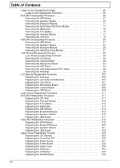
... the TouchPad FFC 126 Replacing the Button Board 127 Replacing the Power Board 129 Replacing the Upper Cover 130 Replacing the Keyboard 134 Replacing the 3G Module 135 Replacing the WLAN Module 136 VIII
... the TouchPad FFC 126 Replacing the Button Board 127 Replacing the Power Board 129 Replacing the Upper Cover 130 Replacing the Keyboard 134 Replacing the 3G Module 135 Replacing the WLAN Module 136 VIII
Aspire One AO531h Service Guide
Page 12
• Acer Email • Wireless • Manufacturing option: Mini-card slot • 802.11b/g support • Two built-in Antenna • Antenna: Has to be placed on the top of LCD • LAN • Atheros solution AR8114/AR8132 • File deployment support • 3G • GSM/GPRS... 30W AC adapter Privacy control • BIOS user, supervisor, HDD passwords • Kensington lock slot Special keys and controls • New Acer flat keyboard • Supports Application keys for Windows XP/Linux version • Support for Home key and Application keys for Windows XP/Linux ...
• Acer Email • Wireless • Manufacturing option: Mini-card slot • 802.11b/g support • Two built-in Antenna • Antenna: Has to be placed on the top of LCD • LAN • Atheros solution AR8114/AR8132 • File deployment support • 3G • GSM/GPRS... 30W AC adapter Privacy control • BIOS user, supervisor, HDD passwords • Kensington lock slot Special keys and controls • New Acer flat keyboard • Supports Application keys for Windows XP/Linux version • Support for Home key and Application keys for Windows XP/Linux ...

Aspire One AO531h Service Guide
Page 16
...Turns the computer on and off. Connects to a display device (e.g. No. 7 Icon 8 9 Closed Front View Item Battery/ Bluetooth/3G/ Wireless LAN communication indicator Click buttons (left and right) Power button/ indicator Description Indicates the status of Battery/ Bluetooth.../3G Wireless LAN communication. (only for certain models) The left and right buttons function like the left and right mouse buttons. No. 1 2 Left View Icon Item Bluetooth communication switch 3G/Wireless communication switch Description Enables/disables the ...
...Turns the computer on and off. Connects to a display device (e.g. No. 7 Icon 8 9 Closed Front View Item Battery/ Bluetooth/3G/ Wireless LAN communication indicator Click buttons (left and right) Power button/ indicator Description Indicates the status of Battery/ Bluetooth.../3G Wireless LAN communication. (only for certain models) The left and right buttons function like the left and right mouse buttons. No. 1 2 Left View Icon Item Bluetooth communication switch 3G/Wireless communication switch Description Enables/disables the ...

Aspire One AO531h Service Guide
Page 18
...the battery in position. 8 Chapter 1 Note: Do not cover or obstruct the cooling vents. Releases the battery for certain models). Accepts a 3G SIM card for 3G connectivity (only for removal. Houses the computer's Wireless LAN module. Bottom View 1 2 3 7 4 6 5 No. 1 2 3 4 5 6 7 Icon ...Item Battery bay 3G SIM card slot Battery release latch Wireless LAN Bay Description Houses the computer's battery pack. Note: The battery shown is for reference only. Ventilation...
...the battery in position. 8 Chapter 1 Note: Do not cover or obstruct the cooling vents. Releases the battery for certain models). Accepts a 3G SIM card for 3G connectivity (only for removal. Houses the computer's Wireless LAN module. Bottom View 1 2 3 7 4 6 5 No. 1 2 3 4 5 6 7 Icon ...Item Battery bay 3G SIM card slot Battery release latch Wireless LAN Bay Description Houses the computer's battery pack. Note: The battery shown is for reference only. Ventilation...

Aspire One AO531h Service Guide
Page 19
Wireless LAN Indicates the status of Wireless LAN communication. 3G communication HDD Indicates the status of Bluetooth communication. Indicates when the hard disk drive is charging. 2. Fully charged: The light shows green when in AC ... when Num Lock is activated. The battery indicator is visible even when the computer cover is closed. Icon Function Bluetooth Description Indicates the status of 3G communication.
Wireless LAN Indicates the status of Wireless LAN communication. 3G communication HDD Indicates the status of Bluetooth communication. Indicates when the hard disk drive is charging. 2. Fully charged: The light shows green when in AC ... when Num Lock is activated. The battery indicator is visible even when the computer cover is closed. Icon Function Bluetooth Description Indicates the status of 3G communication.
Aspire One AO531h Service Guide
Page 29
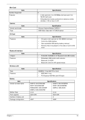
... Number of battery cell Package configuration Specification 2 • 2 mini card slot (1 for 3G/WiMax (full-size) and 1 for WLAN (half-size)) • Embedded 3G module and built-in 2 antenna (combo wireless + 3G) on top of LCD Specification Chicony Camera Module CNF9011 USB Video Class with 1/6"CMOS sensor Specification... • 3G card in mini card slot for 3G/ WiMAX (full-size) • Control by USB interface • User accessible SIM card by battery removal • Antenna: Has ...
... Number of battery cell Package configuration Specification 2 • 2 mini card slot (1 for 3G/WiMax (full-size) and 1 for WLAN (half-size)) • Embedded 3G module and built-in 2 antenna (combo wireless + 3G) on top of LCD Specification Chicony Camera Module CNF9011 USB Video Class with 1/6"CMOS sensor Specification... • 3G card in mini card slot for 3G/ WiMAX (full-size) • Control by USB interface • User accessible SIM card by battery removal • Antenna: Has ...
Aspire One AO531h Service Guide
Page 51
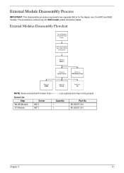
External Module Disassembly Process IMPORTANT: This disassembly procedure represents two separate SKUs for the Aspire one; The procedures outlined use the SSD model unless otherwise stated. Screw List Step WLAN Module 3G Module Screw M2*3 M2*3 Quantity 1 1 Part No. 86.S0207.001 86.S0207.001 Chapter 3 41 External Modules Disassembly Flowchart Turn ... cables from system Rem ove Battery Rem ove Lower Covers Rem ove SD Dummy Card Rem ove DIMM Rem ove WLAN Rem ove 3G NOTE: Items enclosed with broken lines (- - - -) are optional and may not be present. the HDD and SSD models.
External Module Disassembly Process IMPORTANT: This disassembly procedure represents two separate SKUs for the Aspire one; The procedures outlined use the SSD model unless otherwise stated. Screw List Step WLAN Module 3G Module Screw M2*3 M2*3 Quantity 1 1 Part No. 86.S0207.001 86.S0207.001 Chapter 3 41 External Modules Disassembly Flowchart Turn ... cables from system Rem ove Battery Rem ove Lower Covers Rem ove SD Dummy Card Rem ove DIMM Rem ove WLAN Rem ove 3G NOTE: Items enclosed with broken lines (- - - -) are optional and may not be present. the HDD and SSD models.

Aspire One AO531h Service Guide
Page 56
Step WLAN Module Size M2*3 Quantity 1 Screw Type 46 Chapter 3 See "Removing the Lower Covers" on the WLAN Module. IMPORTANT: The black cable attaches to the Main terminal and the white (or gray for models without the optional 3G module) cable attaches to the AUX terminal. 3. Move the antennas away and remove the single screw on page 44. 2. The 3G module on the left of the images may not be present. 1. Disconnect the antenna cables from the WLAN Module. Removing the WLAN Module IMPORTANT: The following disassembly images represent the optional 3G model.
Step WLAN Module Size M2*3 Quantity 1 Screw Type 46 Chapter 3 See "Removing the Lower Covers" on the WLAN Module. IMPORTANT: The black cable attaches to the Main terminal and the white (or gray for models without the optional 3G module) cable attaches to the AUX terminal. 3. Move the antennas away and remove the single screw on page 44. 2. The 3G module on the left of the images may not be present. 1. Disconnect the antenna cables from the WLAN Module. Removing the WLAN Module IMPORTANT: The following disassembly images represent the optional 3G model.

Aspire One AO531h Service Guide
Page 58
IMPORTANT: The yellow cable attaches to the M (Main) terminal and the blue cable attaches to the A (Aux) terminal. 3. Step 3G Module Size M2*3 Quantity 1 Screw Type 48 Chapter 3 Disconnect the antenna cables from the 3G Module. Move the antennas away and remove the single screw on certain models. 1. Removing the 3G Module IMPORTANT: The 3G Module is only available on the 3G Module. See "Removing the Lower Covers" on page 44. 2.
IMPORTANT: The yellow cable attaches to the M (Main) terminal and the blue cable attaches to the A (Aux) terminal. 3. Step 3G Module Size M2*3 Quantity 1 Screw Type 48 Chapter 3 Disconnect the antenna cables from the 3G Module. Move the antennas away and remove the single screw on certain models. 1. Removing the 3G Module IMPORTANT: The 3G Module is only available on the 3G Module. See "Removing the Lower Covers" on page 44. 2.

Aspire One AO531h Service Guide
Page 59
Detach the 3G Module from the socket. Chapter 3 49 NOTE: When reattaching the antennas, ensure the cables are tucked into the chassis to prevent damage. 4.
Detach the 3G Module from the socket. Chapter 3 49 NOTE: When reattaching the antennas, ensure the cables are tucked into the chassis to prevent damage. 4.

Aspire One AO531h Service Guide
Page 73
NOTE: The 3G Module is not supported, only the two WLAN cables must be removed. Disconnect the LCD power cable as shown. 4. Carefully pull the antenna and 3G cables through from the underside of the computer. If 3G is only available on page 54. 2. Lift the adhesive strip securing the LCD power cable in place. 3. Removing the LCD Module 1. See "Removing the Upper Cover" on certain models. Chapter 3 63
NOTE: The 3G Module is not supported, only the two WLAN cables must be removed. Disconnect the LCD power cable as shown. 4. Carefully pull the antenna and 3G cables through from the underside of the computer. If 3G is only available on page 54. 2. Lift the adhesive strip securing the LCD power cable in place. 3. Removing the LCD Module 1. See "Removing the Upper Cover" on certain models. Chapter 3 63

Aspire One AO531h Service Guide
Page 99
... Microphone Board Rem ove LCD Panel Rem ove Camera Module Rem ove LCD FPC Cable Rem ove LCD Brackets Rem ove WLAN Antennas Rem ove 3G Antennas Screw List Step LCD Bezel LCD Panel LCD Brackets Screw M2*5 M2*3 M2*3 Quantity 6 2 4 Part No. 86.S0207.002 Chapter 3 89 LCD ... and that the cables are four antenna cables (white, black, yellow, and blue) addressed during the procedure. NOTE: These disassembly procedures feature the 3G model only, therefore there are replaced in the same position. If 3G is not supported, only the WLAN antennas (white and black) need to be removed.
... Microphone Board Rem ove LCD Panel Rem ove Camera Module Rem ove LCD FPC Cable Rem ove LCD Brackets Rem ove WLAN Antennas Rem ove 3G Antennas Screw List Step LCD Bezel LCD Panel LCD Brackets Screw M2*5 M2*3 M2*3 Quantity 6 2 4 Part No. 86.S0207.002 Chapter 3 89 LCD ... and that the cables are four antenna cables (white, black, yellow, and blue) addressed during the procedure. NOTE: These disassembly procedures feature the 3G model only, therefore there are replaced in the same position. If 3G is not supported, only the WLAN antennas (white and black) need to be removed.

Aspire One AO531h Service Guide
Page 108
Removing the Antennas NOTE: These disassembly procedures feature the 3G model only, therefore there are removed. • A-yellow 3G Antenna cable • B-combined blue 3G Antenna cable, white and black WLAN Antenna cables A B 3. Remove the adhesive strips holding the yellow 3G cable in place. 98 Chapter 3 The LCD Module appears as follows when the... LCD Panel are four antenna cables (white, black, yellow, and blue) addressed during the procedure. See "Removing the LCD Panel" on page 94. 2. If 3G is not supported, only the WLAN antennas (white and black) need to be removed. 1.
Removing the Antennas NOTE: These disassembly procedures feature the 3G model only, therefore there are removed. • A-yellow 3G Antenna cable • B-combined blue 3G Antenna cable, white and black WLAN Antenna cables A B 3. Remove the adhesive strips holding the yellow 3G cable in place. 98 Chapter 3 The LCD Module appears as follows when the... LCD Panel are four antenna cables (white, black, yellow, and blue) addressed during the procedure. See "Removing the LCD Panel" on page 94. 2. If 3G is not supported, only the WLAN antennas (white and black) need to be removed. 1.

Aspire One AO531h Service Guide
Page 109
Carefully pry up the yellow cable 3G Antenna pad, as shown. 5. 4. IMPORTANT: A strong adhesive is used to the module. Remove the cable from the securing clips as shown, and remove the pad from the LCD Module and lift the 3G Antenna cable completely clear of the module. 6. Lift the adhesive pad securing the Antenna pad to secure the Antenna pad in place. Chapter 3 99 Remove the lid sensor magnet from the LCD Module. Take care not to bend the pad during removal.
Carefully pry up the yellow cable 3G Antenna pad, as shown. 5. 4. IMPORTANT: A strong adhesive is used to the module. Remove the cable from the securing clips as shown, and remove the pad from the LCD Module and lift the 3G Antenna cable completely clear of the module. 6. Lift the adhesive pad securing the Antenna pad to secure the Antenna pad in place. Chapter 3 99 Remove the lid sensor magnet from the LCD Module. Take care not to bend the pad during removal.

Aspire One AO531h Service Guide
Page 110
Ensure that the cable is used to the module. 100 Chapter 3 Carefully pry up the white cable WLAN Antenna pad, as shown, and remove the pad from the cable channel as shown. IMPORTANT: A strong adhesive is free of all securing clips. 8. Lift the adhesive pad securing the Antenna pad to bend the pad during removal. 9. Take care not to the module. 7. Lift the adhesive securing the Antenna cable to secure the Antenna pad in place. Remove the combined 3G and WLAN cables from the LCD Module.
Ensure that the cable is used to the module. 100 Chapter 3 Carefully pry up the white cable WLAN Antenna pad, as shown, and remove the pad from the cable channel as shown. IMPORTANT: A strong adhesive is free of all securing clips. 8. Lift the adhesive pad securing the Antenna pad to bend the pad during removal. 9. Take care not to the module. 7. Lift the adhesive securing the Antenna cable to secure the Antenna pad in place. Remove the combined 3G and WLAN cables from the LCD Module.

Aspire One AO531h Service Guide
Page 111
IMPORTANT: A strong adhesive is used to the module. Lift the adhesive pad securing the Antenna pad to secure the Antenna pad in place. Take care not to the module. 11. Remove the adhesive tape securing the white WLAN cable to bend the pad during removal. Carefully pry up the blue and black cable 3G and WLAN Antenna pad, as shown, and remove the pad from the LCD Module. Chapter 3 101 10.
IMPORTANT: A strong adhesive is used to the module. Lift the adhesive pad securing the Antenna pad to secure the Antenna pad in place. Take care not to the module. 11. Remove the adhesive tape securing the white WLAN cable to bend the pad during removal. Carefully pry up the blue and black cable 3G and WLAN Antenna pad, as shown, and remove the pad from the LCD Module. Chapter 3 101 10.

Aspire One AO531h Service Guide
Page 112
cable in place. 2. Press down the pad and adhesive tape, as shown, using 3. Replace the WLAN Antenna cable as indicated, to secure it in place. 4. Replace the adhesive tape to the combined 3G and WLAN Antenna pad. 102 Chapter 3 Replace the adhesive tape securing the WLAN Antenna to secure the WLAN all available cable clips. Replace the combined 3G and WLAN Antenna pad as shown. LCD Module Reassembly Procedure Replacing the Antennas 1.
cable in place. 2. Press down the pad and adhesive tape, as shown, using 3. Replace the WLAN Antenna cable as indicated, to secure it in place. 4. Replace the adhesive tape to the combined 3G and WLAN Antenna pad. 102 Chapter 3 Replace the adhesive tape securing the WLAN Antenna to secure the WLAN all available cable clips. Replace the combined 3G and WLAN Antenna pad as shown. LCD Module Reassembly Procedure Replacing the Antennas 1.
