
Aspire M5620 Service Guide
Page 6
... Rear Panel 15 Hardware Specifications and Configurations 16 Power Management Function (ACPI support function 22 Chapter 2 System Utilities 23 Entering Setup 24 Product Information 26 Standard CMOS Features 27 Advanced BIOS Features 30 Integrated Peripherals 34 Power Management 41 PnP/PCI Configuration 44 PC Health Status 46 Frequency/Voltage Control 47 Load Default Settings 49 Set Supervisor/User Password 50 Save & Exit Setup 52 Exit Without Saving 53 Chapter 3 Machine Disassembly and Replacement 54 General Information 55 Disassembly...
... Rear Panel 15 Hardware Specifications and Configurations 16 Power Management Function (ACPI support function 22 Chapter 2 System Utilities 23 Entering Setup 24 Product Information 26 Standard CMOS Features 27 Advanced BIOS Features 30 Integrated Peripherals 34 Power Management 41 PnP/PCI Configuration 44 PC Health Status 46 Frequency/Voltage Control 47 Load Default Settings 49 Set Supervisor/User Password 50 Save & Exit Setup 52 Exit Without Saving 53 Chapter 3 Machine Disassembly and Replacement 54 General Information 55 Disassembly...

Aspire M5620 Service Guide
Page 12
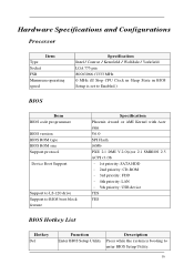
Data transfer rate support: USB 2.0/1.1 1394 Controller: VIA TSB43AB23PDTG4 1 on board header 1 6-pin 1394 port on rear port BIOS BIOS Type: Phoenix Award or AMI Kernel with Acer skin BIOS 16Mb Flash BIOS Note: Boot ROM should be included (PXE function should be built in with default and RPL function is optional by service BIOS) Compliant with latest ASF 2.0 spec 6
Data transfer rate support: USB 2.0/1.1 1394 Controller: VIA TSB43AB23PDTG4 1 on board header 1 6-pin 1394 port on rear port BIOS BIOS Type: Phoenix Award or AMI Kernel with Acer skin BIOS 16Mb Flash BIOS Note: Boot ROM should be included (PXE function should be built in with default and RPL function is optional by service BIOS) Compliant with latest ASF 2.0 spec 6

Aspire M5620 Service Guide
Page 13
Compliant with latest SMT 2.0 spec Compliant with latest Intel Virtualization Technology spec I/O Connector Controller: Super I/O ITE 8718F-EX with hardware monitor Rear I/O Connector 1 Parallel port, 1 serial port 1 D-Sub VGA port 1 RJ45 LAN port 6 USB ports 7.1 channel phone jack ( 6 audio jacks) 1 6-pin 1394 port On-board connectors 1 LGA 775 CPU socket 7
Compliant with latest SMT 2.0 spec Compliant with latest Intel Virtualization Technology spec I/O Connector Controller: Super I/O ITE 8718F-EX with hardware monitor Rear I/O Connector 1 Parallel port, 1 serial port 1 D-Sub VGA port 1 RJ45 LAN port 6 USB ports 7.1 channel phone jack ( 6 audio jacks) 1 6-pin 1394 port On-board connectors 1 LGA 775 CPU socket 7

Aspire M5620 Service Guide
Page 18
Aspire M5620 Front Panel The computer's front panel consists of the following: Label 1 2 3 4 5 6 7 Description Optical drive Card reader Power and HDD LED Power button Speaker or headphone Microphone jack USB ports 12
Aspire M5620 Front Panel The computer's front panel consists of the following: Label 1 2 3 4 5 6 7 Description Optical drive Card reader Power and HDD LED Power button Speaker or headphone Microphone jack USB ports 12
Aspire M5620 Service Guide
Page 19
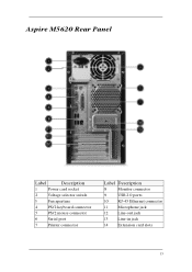
Aspire M5620 Rear Panel Label Description 1 Power card socket 2 Voltage selector switch 3 Fan aperture 4 PS/2 keyboard connector 5 PS/2 mouse connector 6 Serial port 7 Printer connector Label Description 8 Monitor connector 9 USB 2.0 ports 10 RJ-45 Ethernet connector 11 Microphone jack 12 Line-out jack 13 Line-in jack 14 Extension card slots 13
Aspire M5620 Rear Panel Label Description 1 Power card socket 2 Voltage selector switch 3 Fan aperture 4 PS/2 keyboard connector 5 PS/2 mouse connector 6 Serial port 7 Printer connector Label Description 8 Monitor connector 9 USB 2.0 ports 10 RJ-45 Ethernet connector 11 Microphone jack 12 Line-out jack 13 Line-in jack 14 Extension card slots 13
Aspire M5620 Service Guide
Page 21
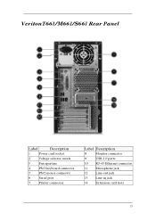
VeritonT661/M661/S661 Rear Panel Label Description 1 Power card socket 2 Voltage selector switch 3 Fan aperture 4 PS/2 keyboard connector 5 PS/2 mouse connector 6 Serial port 7 Printer connector Label Description 8 Monitor connector 9 USB 2.0 ports 10 RJ-45 Ethernet connector 11 Microphone jack 12 Line-out jack 13 Line-in jack 14 Extension card slots 15
VeritonT661/M661/S661 Rear Panel Label Description 1 Power card socket 2 Voltage selector switch 3 Fan aperture 4 PS/2 keyboard connector 5 PS/2 mouse connector 6 Serial port 7 Printer connector Label Description 8 Monitor connector 9 USB 2.0 ports 10 RJ-45 Ethernet connector 11 Microphone jack 12 Line-out jack 13 Line-in jack 14 Extension card slots 15
Aspire M5620 Service Guide
Page 22
... Sleep State in BIOS Setup is set to Enabled.) BIOS Item BIOS code programmer BIOS version BIOS ROM type BIOS ROM size Support protocol Device Boot Support Support to LS-120 drive Support to BIOS boot block feature Specification Phoenix Award or AMI Kernel with Acer skin V6.0 SPI Flash 16Mb PXE 2.1 DMI V.2.0(s)or 2.1 SMBIOS 2.5 ACPI v3.0b - 1st priority: SATA HDD - 2nd priority: CD-ROM - 3rd priority: FDD - 4th priority: LAN - 5th priority: USB device YES YES BIOS Hotkey List Hotkey Del Function Enter BIOS Setup Utility...
... Sleep State in BIOS Setup is set to Enabled.) BIOS Item BIOS code programmer BIOS version BIOS ROM type BIOS ROM size Support protocol Device Boot Support Support to LS-120 drive Support to BIOS boot block feature Specification Phoenix Award or AMI Kernel with Acer skin V6.0 SPI Flash 16Mb PXE 2.1 DMI V.2.0(s)or 2.1 SMBIOS 2.5 ACPI v3.0b - 1st priority: SATA HDD - 2nd priority: CD-ROM - 3rd priority: FDD - 4th priority: LAN - 5th priority: USB device YES YES BIOS Hotkey List Hotkey Del Function Enter BIOS Setup Utility...

Aspire M5620 Service Guide
Page 24
... Specification Intel ICH9R ALC888S codec 7.1 Enable/disable by BIOS Setup Stereo Sound Blaster Pro/16 compatible Mixed digital and analog high performance chip Enhanced stereo full duplex operation High performance audio accelerator and AC'97 support Full native DOS games compatibility Virtual FM enhances audio experience through real-time FM-to error correction code (ECC) feature Memory module combinations Yes No You can install memory...
... Specification Intel ICH9R ALC888S codec 7.1 Enable/disable by BIOS Setup Stereo Sound Blaster Pro/16 compatible Mixed digital and analog high performance chip Enhanced stereo full duplex operation High performance audio accelerator and AC'97 support Full native DOS games compatibility Virtual FM enhances audio experience through real-time FM-to error correction code (ECC) feature Memory module combinations Yes No You can install memory...

Aspire M5620 Service Guide
Page 25
...Specification Floppy disk drive controller ITE 8718 Floppy disk drive controller resident bus ISA bus Support FDD format 360KB, 720KB, 1.2MB, 1.44MB, 2.88MB Parallel Port Item Parallel port controller Parallel port controller resident bus Number of parallel parts Support ECP/EPP Connector type Parallel port function control Optional EV+CP DMA channel (in BIOS setup) Optional parallel port I/O address (via BIOS setup) Optional parallel port IRQ (via BIOS setup) Specification ITE 8718 ISA bus 1 SPP / Bi-directional / ECP / EPP 25-pin D-type female connector Enable/disable by BIOS Setup...
...Specification Floppy disk drive controller ITE 8718 Floppy disk drive controller resident bus ISA bus Support FDD format 360KB, 720KB, 1.2MB, 1.44MB, 2.88MB Parallel Port Item Parallel port controller Parallel port controller resident bus Number of parallel parts Support ECP/EPP Connector type Parallel port function control Optional EV+CP DMA channel (in BIOS setup) Optional parallel port I/O address (via BIOS setup) Optional parallel port IRQ (via BIOS setup) Specification ITE 8718 ISA bus 1 SPP / Bi-directional / ECP / EPP 25-pin D-type female connector Enable/disable by BIOS Setup...
Aspire M5620 Service Guide
Page 26
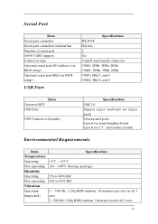
Serial Port Item Serial port controller Serial port controller resident bus Number of serial port 16550 UART support Connector type Optional serial port I/O address (via BIOS setup) Optional serial port IRQ (via BIOS setup) USB Port Specification ITE 8718 ISA bus 2 Yes 9-pin D-type female connector COM1: 2F8h, 3E8h, 2E8h COM2: 3E8h, 3F8h, 2F8h COM1: IRQ 3, and 4 COM2: IRQ 4, and 3 Universal HCI USB Class Item USB Connectors Quantity Specification USB 2.0 Support legacy keyboard for legacy mode 6 back panel ports 4 ports for front daughter board 2 ports for 3.5'' card reader module ...
Serial Port Item Serial port controller Serial port controller resident bus Number of serial port 16550 UART support Connector type Optional serial port I/O address (via BIOS setup) Optional serial port IRQ (via BIOS setup) USB Port Specification ITE 8718 ISA bus 2 Yes 9-pin D-type female connector COM1: 2F8h, 3E8h, 2E8h COM2: 3E8h, 3F8h, 2F8h COM1: IRQ 3, and 4 COM2: IRQ 4, and 3 Universal HCI USB Class Item USB Connectors Quantity Specification USB 2.0 Support legacy keyboard for legacy mode 6 back panel ports 4 ports for front daughter board 2 ports for 3.5'' card reader module ...

Aspire M5620 Service Guide
Page 27
Power Management Devices S1 S3 S4 Power Button V V V USB Keyboard/Mouse V V N/A PME Disabled Disabled Disabled RCT Disabled Disabled Disabled WOR Disabled Disabled Disabled Devices wake up from S3 should be less than Devices wake up from S5 should be less than 10 seconds S5 V N/A Disabled Disabled Disabled 21
Power Management Devices S1 S3 S4 Power Button V V V USB Keyboard/Mouse V V N/A PME Disabled Disabled Disabled RCT Disabled Disabled Disabled WOR Disabled Disabled Disabled Devices wake up from S3 should be less than Devices wake up from S5 should be less than 10 seconds S5 V N/A Disabled Disabled Disabled 21

Aspire M5620 Service Guide
Page 30
Entering Setup Power on the screen, press the key of [Delete] to enter Setup, restart the system by simultaneously pressing [Ctrl+ Alt+ Delete]. The Setup Utility main menu then appears: 24 When the message of "Press DEL to enter SETUP" appears on the computer and the system will start POST (Power On Self Test) process. You may also restart the system by turning it OFF and On. NOTE: If the message disappears before you respond and you still wish to enter the setup menu.
Entering Setup Power on the screen, press the key of [Delete] to enter Setup, restart the system by simultaneously pressing [Ctrl+ Alt+ Delete]. The Setup Utility main menu then appears: 24 When the message of "Press DEL to enter SETUP" appears on the computer and the system will start POST (Power On Self Test) process. You may also restart the system by turning it OFF and On. NOTE: If the message disappears before you respond and you still wish to enter the setup menu.
Aspire M5620 Service Guide
Page 35
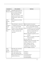
...: Number of sectors Video Select the type of CPU Total Total memory size for the Memory system Size IDE Hard disk drive connected [Enter] for the hard drive. This is always automatically detection step and allow for detected faster system start up [Manual]: Manually input the correct settings [Access Mode]: To set the access mode for detection options Channel X to select the situation if the BIOS stops the POST process and the notification All Errors...
...: Number of sectors Video Select the type of CPU Total Total memory size for the Memory system Size IDE Hard disk drive connected [Enter] for the hard drive. This is always automatically detection step and allow for detected faster system start up [Manual]: Manually input the correct settings [Access Mode]: To set the access mode for detection options Channel X to select the situation if the BIOS stops the POST process and the notification All Errors...
Aspire M5620 Service Guide
Page 37
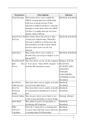
... option is used to set keyboard is enabled, it will beep. If this function is enabled and there is someone attempts to write data to this function is number keys or arrow [Disabled] Status keys Security Option This category allows you to quick power on screen and the alarm will decrease the time needed to boot the system, which allows your hard disk [Enabled], S.M.A.R.T to skip [Enabled], [Disabled] Self Test certain tests while booting...
... option is used to set keyboard is enabled, it will beep. If this function is enabled and there is someone attempts to write data to this function is number keys or arrow [Disabled] Status keys Security Option This category allows you to quick power on screen and the alarm will decrease the time needed to boot the system, which allows your hard disk [Enabled], S.M.A.R.T to skip [Enabled], [Disabled] Self Test certain tests while booting...
Aspire M5620 Service Guide
Page 39
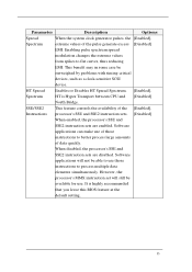
... problems with timing-critical devices, such as a clock-sensitive SCSI device. It is Hyper Transport between CPU and [Disabled] North Bridge. HT Spread Enables or Disables HT Spread Spectrum. [Enabled], Spectrum HT is highly recommended that you leave this BIOS feature at the default setting. 33 Parameter Description Options Spread When the system clock generator pulses, the [Enabled], Spectrum extreme values of the [Enabled], Instructions processor...
... problems with timing-critical devices, such as a clock-sensitive SCSI device. It is Hyper Transport between CPU and [Disabled] North Bridge. HT Spread Enables or Disables HT Spread Spectrum. [Enabled], Spectrum HT is highly recommended that you leave this BIOS feature at the default setting. 33 Parameter Description Options Spread When the system clock generator pulses, the [Enabled], Spectrum extreme values of the [Enabled], Instructions processor...
Aspire M5620 Service Guide
Page 42
... Options IDE The four IDE PIO fields let you set this menu. Select Enabled to enable or disable [Enabled], Transfer Access DMA transfer access of the four IDE devices that the ry Master/Slave onboard IDE interface supports. Select Disabled to deactivate an interface, if you install a primary and/or secondary add-in the four IDE UDMA fields (for each of IDE device (or IDE [Disabled] HDD) SATA 1/2 Enable/Disable Serial...
... Options IDE The four IDE PIO fields let you set this menu. Select Enabled to enable or disable [Enabled], Transfer Access DMA transfer access of the four IDE devices that the ry Master/Slave onboard IDE interface supports. Select Disabled to deactivate an interface, if you install a primary and/or secondary add-in the four IDE UDMA fields (for each of IDE device (or IDE [Disabled] HDD) SATA 1/2 Enable/Disable Serial...

Aspire M5620 Service Guide
Page 43
This category allows you to determine the [Auto], speed of block read /write. If your IDE hard drive supports block mode(most new drives do), select Enabled for automatic detection of the optimal number of SATA port. Parameter Description Options IDE HDD Block Mode SATA PORT Speed Settings Block mode is also called block transfer, [Enabled], multiple commands, or multiple sectors [Disabled] read /write per sector the drive can support. Integrated Peripherals-Onboard Device Setup 37
This category allows you to determine the [Auto], speed of block read /write. If your IDE hard drive supports block mode(most new drives do), select Enabled for automatic detection of the optimal number of SATA port. Parameter Description Options IDE HDD Block Mode SATA PORT Speed Settings Block mode is also called block transfer, [Enabled], multiple commands, or multiple sectors [Disabled] read /write per sector the drive can support. Integrated Peripherals-Onboard Device Setup 37
Aspire M5620 Service Guide
Page 44
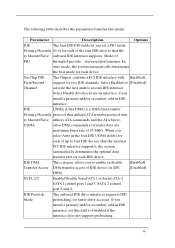
...the [Disabled] motherboard's onboard LAN controller, you should certainly enable this BIOS feature. This may free up an IRQ for other devices to use . Parameter Description Options On Chip USB This field allows you do not want to shadow or Base memory. [Base Memory] USB KB Legacy This field enables or disables USB [Enabled], Support keyboard support function. [Disabled] USB Mouse Support This field enables or disables USB [Enabled], mouse support function. [Disabled] AC 97 Audio Change the on board LAN boot [Enabled], ROM ROM. [Disabled] 38 This is useful if...
...the [Disabled] motherboard's onboard LAN controller, you should certainly enable this BIOS feature. This may free up an IRQ for other devices to use . Parameter Description Options On Chip USB This field allows you do not want to shadow or Base memory. [Base Memory] USB KB Legacy This field enables or disables USB [Enabled], Support keyboard support function. [Disabled] USB Mouse Support This field enables or disables USB [Enabled], mouse support function. [Disabled] AC 97 Audio Change the on board LAN boot [Enabled], ROM ROM. [Disabled] 38 This is useful if...

Aspire M5620 Service Guide
Page 46
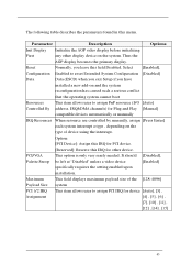
... serial port. Parallel Port Select an operating mode for the onboard [Normal], [EPP], Mode parallel (printer) port. [EPP], [EPP+ECP] ECP Mode used This item allows users to the IR port. Select an address and corresponding interrupt for ECP mode 40 Mode Full-duplex mode permits simultaneous tow-direction transmission. Parameter Description Options Onboard FDC Select Enabled if your system has a floppy disk [Enabled]. Controller controller (FDC) installed on the system board [Disabled...
... serial port. Parallel Port Select an operating mode for the onboard [Normal], [EPP], Mode parallel (printer) port. [EPP], [EPP+ECP] ECP Mode used This item allows users to the IR port. Select an address and corresponding interrupt for ECP mode 40 Mode Full-duplex mode permits simultaneous tow-direction transmission. Parameter Description Options Onboard FDC Select Enabled if your system has a floppy disk [Enabled]. Controller controller (FDC) installed on the system board [Disabled...
Aspire M5620 Service Guide
Page 51
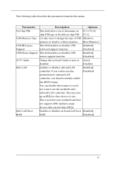
... "Disabled" unless a video device [Enabled] specifically requires the setting enabled upon installation. Maximum This field displays maximum payload size of the [128-4096] Payload Size system PCI 1/2 IRQ This item allows user to assign PnP resource (I/O [Auto] Controlled By address, IRQ&DMA channels) for device [Auto], [3] , Assignment [4] , [5] , [6] , [7], [10] , [11] , [12] , [14] , [15] 45 PCI/VGA This option is only very rarely needed. Select [Enabled], Configuration Enabled to reset Extended System Configuration [Disabled] Data...
... "Disabled" unless a video device [Enabled] specifically requires the setting enabled upon installation. Maximum This field displays maximum payload size of the [128-4096] Payload Size system PCI 1/2 IRQ This item allows user to assign PnP resource (I/O [Auto] Controlled By address, IRQ&DMA channels) for device [Auto], [3] , Assignment [4] , [5] , [6] , [7], [10] , [11] , [12] , [14] , [15] 45 PCI/VGA This option is only very rarely needed. Select [Enabled], Configuration Enabled to reset Extended System Configuration [Disabled] Data...


