Service Guide
Page 7
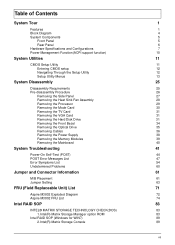
...4 System Components 5 Front Panel 5 Rear Panel 6 Hardware Specifications and Configurations 7 Power Management Function(ACPI support function) 10 System Utilities 11 CMOS Setup Utility 11 Entering CMOS...Power Supply 38 Removing the Memory Modules 39 Removing the Mainboard 40 System Troubleshooting 41 Power-On Self-Test (POST) 44 POST Error Messages List 47 Error Symptoms List 54 Undetermined Problems 60 Jumper and Connector Information 61 M/B Placement 61 Jumper Setting 63 FRU (Field Replaceable Unit) List 71 Aspire M3802 Exploded Diagram 72 Aspire M3802...
...4 System Components 5 Front Panel 5 Rear Panel 6 Hardware Specifications and Configurations 7 Power Management Function(ACPI support function) 10 System Utilities 11 CMOS Setup Utility 11 Entering CMOS...Power Supply 38 Removing the Memory Modules 39 Removing the Mainboard 40 System Troubleshooting 41 Power-On Self-Test (POST) 44 POST Error Messages List 47 Error Symptoms List 54 Undetermined Problems 60 Jumper and Connector Information 61 M/B Placement 61 Jumper Setting 63 FRU (Field Replaceable Unit) List 71 Aspire M3802 Exploded Diagram 72 Aspire M3802...
Service Guide
Page 10
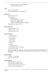
...-MS(M2), xD type M and Type H card, CF type I and II, Microdrive) System BIOS • Size: 2Mb Use SPI Flash • AMI Kernel with Acer skin Power supply • 500W/300W/250W in stable mode • Active PFC 220V for EMEA and China • Non-PFC 110V and 220V with select switch. •...
...-MS(M2), xD type M and Type H card, CF type I and II, Microdrive) System BIOS • Size: 2Mb Use SPI Flash • AMI Kernel with Acer skin Power supply • 500W/300W/250W in stable mode • Active PFC 220V for EMEA and China • Non-PFC 110V and 220V with select switch. •...

Service Guide
Page 45
Lift the power supply module out of the chassis. 38 Chapter 3 Removing the Power Supply 1. Disconnect the 24-pin and 4-pin power supply cables from the mainboard. 2. Remove the four screw that secures the power supply to the chassis. 3.
Lift the power supply module out of the chassis. 38 Chapter 3 Removing the Power Supply 1. Disconnect the 24-pin and 4-pin power supply cables from the mainboard. 2. Remove the four screw that secures the power supply to the chassis. 3.
Service Guide
Page 54
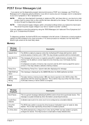
...the check procedure. A diskette was unable to properly configure the device. This may be done through the diagnostics program. NOTE: Check all power supply voltages, switch, and jumper settings before you replace the main board. This condition may occur from a particular device. This is present.... Failure ... Invalid Boot Diskette Drive Not Ready A: Drive Error Description This is the most likely cause. Chapter 4 47 Also check the power supply voltages if you have done so, you must run the diagnostics program tests but did receive a POST error message, use "POST Error ...
...the check procedure. A diskette was unable to properly configure the device. This may be done through the diagnostics program. NOTE: Check all power supply voltages, switch, and jumper settings before you replace the main board. This condition may occur from a particular device. This is present.... Failure ... Invalid Boot Diskette Drive Not Ready A: Drive Error Description This is the most likely cause. Chapter 4 47 Also check the power supply voltages if you have done so, you must run the diagnostics program tests but did receive a POST error message, use "POST Error ...

Service Guide
Page 61
Ensure the system is not in power saving mode.See "Power Management"in the check procedure. If the reading shows normal, but the fan still does not work . 1.Diskette/IDE drive connection/cables 2. System works but power supply fan runs. 1. If directed to master.) Media and drive ...are clean before diagnosing any processor problems. Processor fan does not run but fails to enter power saving mode when the Power Management Mode is set to a check procedure,...
Ensure the system is not in power saving mode.See "Power Management"in the check procedure. If the reading shows normal, but the fan still does not work . 1.Diskette/IDE drive connection/cables 2. System works but power supply fan runs. 1. If directed to master.) Media and drive ...are clean before diagnosing any processor problems. Processor fan does not run but fails to enter power saving mode when the Power Management Mode is set to a check procedure,...
Service Guide
Page 64
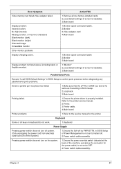
... keys on keyboard do not work. 1.Keyboard Power Supply Pressing power switch does not turn off system. (Only unplugging the power cord from electrical outlet can turn off the system.) 1.Ensure the Soft-off . 2.Power switch cable assembly Pressing power switch does not turn on the system. 1.Ensure the power override switch (situated at the back of...
... keys on keyboard do not work. 1.Keyboard Power Supply Pressing power switch does not turn off system. (Only unplugging the power cord from electrical outlet can turn off the system.) 1.Ensure the Soft-off . 2.Power switch cable assembly Pressing power switch does not turn on the system. 1.Ensure the power override switch (situated at the back of...

Service Guide
Page 65
No system power, or power supply fan is not running. 1.Power Supply 2.Main board Other Problems Any other problems. 1.Undetermined Problems 58 Chapter 4 Error Symptom Executing software shutdown from Recovery CD. Action/FRU 1.Load default settings. 2.Reload software from Windows98 Start menu does not turn off the system. (Only pressing power switch can turn off the system).
No system power, or power supply fan is not running. 1.Power Supply 2.Main board Other Problems Any other problems. 1.Undetermined Problems 58 Chapter 4 Error Symptom Executing software shutdown from Recovery CD. Action/FRU 1.Load default settings. 2.Reload software from Windows98 Start menu does not turn off the system. (Only pressing power switch can turn off the system).

Service Guide
Page 66
...the problem FRU. 4. Perform the following checks, one by one at a time: 10. Load default settings in "or "Error Symptoms List" on page 87. Non-Acer devices • External devices • Any adapter card (modem card, LAN card or video card, if installed) • CD/DVD-ROM drive • Diskette ... and connectors for proper installation. 9. If you find the failing device or adapter. Check all main board jumper positions and switch settings. 6. Check the power supply voltage. If the jumpers, switches and voltage settings are correct continue with this check: 1. Chapter 4 59...
...the problem FRU. 4. Perform the following checks, one by one at a time: 10. Load default settings in "or "Error Symptoms List" on page 87. Non-Acer devices • External devices • Any adapter card (modem card, LAN card or video card, if installed) • CD/DVD-ROM drive • Diskette ... and connectors for proper installation. 9. If you find the failing device or adapter. Check all main board jumper positions and switch settings. 6. Check the power supply voltage. If the jumpers, switches and voltage settings are correct continue with this check: 1. Chapter 4 59...


