
Acer Aspire M3470 Service Guide
Page 7
... Pre-disassembly Procedure 25 Removing the Side Panel 26 Removing the Front Bezel 27 Removing the Heat Sink Fan Assembly 28 Removing the Processor 30 Removing the TV-Tuner Card 32 Removing the VGA Card 34 Removing the Hard Disk Drive 35 Removing the Optical Drive 37 Removing the Power Supply 39 Removing the System Fan 41 Removing the Memory Modules 42 Removing the Mainboard 43 Removing the Top Cover 46 Removing the Power Switch and LED Cable Assembly 48 Removing the Card Reader 49 Removing the Top USB and Audio...
... Pre-disassembly Procedure 25 Removing the Side Panel 26 Removing the Front Bezel 27 Removing the Heat Sink Fan Assembly 28 Removing the Processor 30 Removing the TV-Tuner Card 32 Removing the VGA Card 34 Removing the Hard Disk Drive 35 Removing the Optical Drive 37 Removing the Power Supply 39 Removing the System Fan 41 Removing the Memory Modules 42 Removing the Mainboard 43 Removing the Top Cover 46 Removing the Power Switch and LED Cable Assembly 48 Removing the Card Reader 49 Removing the Top USB and Audio...
Acer Aspire M3470 Service Guide
Page 8
System Troubleshooting 76 Hardware Diagnostic Procedure 76 System Check Procedures 77 Power System Check 77 System External Inspection 77 System Internal Inspection 77 Beep Codes 78 Checkpoints 79 BIOS Recovery 82 Jumper and Connector Information 83 M/B Placement 83 Jumper Setting 85 Setting Jumper 85 FRU (Field Replaceable Unit) List 92 Aspire M3470 Exploded Diagram 93 Aspire M3470 FRU List 95 viii
System Troubleshooting 76 Hardware Diagnostic Procedure 76 System Check Procedures 77 Power System Check 77 System External Inspection 77 System Internal Inspection 77 Beep Codes 78 Checkpoints 79 BIOS Recovery 82 Jumper and Connector Information 83 M/B Placement 83 Jumper Setting 85 Setting Jumper 85 FRU (Field Replaceable Unit) List 92 Aspire M3470 Exploded Diagram 93 Aspire M3470 FRU List 95 viii
Acer Aspire M3470 Service Guide
Page 9
... listed in 2 same memory size DDRIII. Different colors for DIMM 0 and DIMM 1. • Dual channel should be enabled always when plug-in this section is a brief summary of 16 GB supported (using 4Gb tech). • Support DDR3 1.5V 1066/1333 (1GB / 2GB / 4GB). Graphics • HD Graphics Support • Dual independent display -- HDMI and VGA. • Digital displayHDMI with HDMI CTS 1.4 compliance. • Need to measure VGA follow Acer VGA...
... listed in 2 same memory size DDRIII. Different colors for DIMM 0 and DIMM 1. • Dual channel should be enabled always when plug-in this section is a brief summary of 16 GB supported (using 4Gb tech). • Support DDR3 1.5V 1066/1333 (1GB / 2GB / 4GB). Graphics • HD Graphics Support • Dual independent display -- HDMI and VGA. • Digital displayHDMI with HDMI CTS 1.4 compliance. • Need to measure VGA follow Acer VGA...

Acer Aspire M3470 Service Guide
Page 10
...; Support DVD-ROM, DVD-SuperMulti, BD-combo, BD-rewrite • Maximum ODD depth to support for internal SATA port. • Monitor compatible is requested to the monitor AVL and DQM recommended list. • Must with bezel • Models are listed on AVLC Graphics card • One PCI-E x 16 graphics card. • No mechanical retriction to 185mm with latch in slot. Native IDE mode in Microsoft windows OS. Serial ATA controller • Slot Type: SATA connector • SATA ports quantity: 3(SATA...
...; Support DVD-ROM, DVD-SuperMulti, BD-combo, BD-rewrite • Maximum ODD depth to support for internal SATA port. • Monitor compatible is requested to the monitor AVL and DQM recommended list. • Must with bezel • Models are listed on AVLC Graphics card • One PCI-E x 16 graphics card. • No mechanical retriction to 185mm with latch in slot. Native IDE mode in Microsoft windows OS. Serial ATA controller • Slot Type: SATA connector • SATA ports quantity: 3(SATA...
Acer Aspire M3470 Service Guide
Page 11
....0 ports • 1 * 3 ports Audio jack On-board connectors • 1 * 24-pin ATX PWR connector • 1 * H2X2 Power Supply Connector • 3 * SATA 6Gb/s for A75 • 3 * USB2.0 H5X2 Header • 1 * USB3.0 2*10 Header • 1 * Front Audio Pannel H5X2 header • 1 * Front Panel IO H7X2 Header • 1 * H1X4 CPU with SAMRT FAN • 1 * H1X4 System with SAMRT FAN • 1 * H1X4 SPDIFOUT Header • 1 * H3X1 Clear CMOS Header • 1 * H2X4 HD internal speaker...
....0 ports • 1 * 3 ports Audio jack On-board connectors • 1 * 24-pin ATX PWR connector • 1 * H2X2 Power Supply Connector • 3 * SATA 6Gb/s for A75 • 3 * USB2.0 H5X2 Header • 1 * USB3.0 2*10 Header • 1 * Front Audio Pannel H5X2 header • 1 * Front Panel IO H7X2 Header • 1 * H1X4 CPU with SAMRT FAN • 1 * H1X4 System with SAMRT FAN • 1 * H1X4 SPDIFOUT Header • 1 * H3X1 Clear CMOS Header • 1 * H2X4 HD internal speaker...
Acer Aspire M3470 Service Guide
Page 15
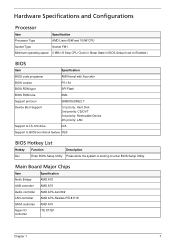
Hardware Specifications and Configurations Processor Item Specification Processor Type AMD Liano 65W and 100W CPU Socket Type Socket FM1 Minimum operating speed 0 MHz (If Stop CPU Clock in Sleep State in BIOS Setup is set to Enabled.) BIOS Item Specification BIOS code programer AMI Kernel with Acer skin BIOS version P01-A1 BIOS ROM type SPI Flash BIOS ROM size 2Mb Support protocol SMBIOS(DMI)2.7 Device Boot Support 1st priority: Hard Disk 2nd priority: CD/DVT 3rd priority: Removable Device 4th priority: LAN Support to LS-120 drive N/A Support to BIOS boot block ...
Hardware Specifications and Configurations Processor Item Specification Processor Type AMD Liano 65W and 100W CPU Socket Type Socket FM1 Minimum operating speed 0 MHz (If Stop CPU Clock in Sleep State in BIOS Setup is set to Enabled.) BIOS Item Specification BIOS code programer AMI Kernel with Acer skin BIOS version P01-A1 BIOS ROM type SPI Flash BIOS ROM size 2Mb Support protocol SMBIOS(DMI)2.7 Device Boot Support 1st priority: Hard Disk 2nd priority: CD/DVT 3rd priority: Removable Device 4th priority: LAN Support to LS-120 drive N/A Support to BIOS boot block ...

Acer Aspire M3470 Service Guide
Page 16
... memory voltage 1.5V Support memory module package 240-pin DDRIII Support to parity check feature Yes Support to error correction code (ECC) feature No Memory module combinations You can install memory modules in Chassis top side. SATA Interface Item SATA controller Number of SATA channel Support mode Specification AMD A75 SATA X 3(SATA 6Gb/s) AHCI/IDE mode option USB Port Item Universal HCI USB Class USB Connectors Quantity Specification USB 2.0/1.1 or USB 3.0 Support legacy keyboard for legacy mode 4 USB2.0 ports locate on MB rear side. 2 USB3.0 ports locate on MB rear...
... memory voltage 1.5V Support memory module package 240-pin DDRIII Support to parity check feature Yes Support to error correction code (ECC) feature No Memory module combinations You can install memory modules in Chassis top side. SATA Interface Item SATA controller Number of SATA channel Support mode Specification AMD A75 SATA X 3(SATA 6Gb/s) AHCI/IDE mode option USB Port Item Universal HCI USB Class USB Connectors Quantity Specification USB 2.0/1.1 or USB 3.0 Support legacy keyboard for legacy mode 4 USB2.0 ports locate on MB rear side. 2 USB3.0 ports locate on MB rear...
Acer Aspire M3470 Service Guide
Page 17
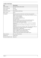
... Definition audio controller ALC662 2.1 channel Enable/disable by BIOS Setup Stereo Meets the latest Microsoft Windows Logo Program audio specification WaveRT based audio function driver and logo ready for Windows 7 and Vista EAX™ 1.0 & 2.0 compatible Direct Sound 3D™ compatible I3DL2 compatible (Windows XP only) 3D Positional Audio Emulation of 26 sound environments to enhance gaming experience Multi-band software equalizer and software tools are provided Voice Cancellation and Key...
... Definition audio controller ALC662 2.1 channel Enable/disable by BIOS Setup Stereo Meets the latest Microsoft Windows Logo Program audio specification WaveRT based audio function driver and logo ready for Windows 7 and Vista EAX™ 1.0 & 2.0 compatible Direct Sound 3D™ compatible I3DL2 compatible (Windows XP only) 3D Positional Audio Emulation of 26 sound environments to enhance gaming experience Multi-band software equalizer and software tools are provided Voice Cancellation and Key...

Acer Aspire M3470 Service Guide
Page 18
...% to 90% RH Vibration Operating (unpacked) 5 ~ 500 Hz: 2.20g RMS random, 10 minutes per axis in all 3 axes. 5 ~500 Hz: 1.09g RMS random, 1 hour per axis in all 3 axes. S5 V N/A Disabled Disabled Disabled 10 Chapter 1 Power Management Devices S1 S3 S4 Power Button V V V USB Keyboard/Mouse V V N/A PME Disabled Disabled Disabled RCT Disabled Disabled Disabled WOR Disabled Disabled Disabled • Devices wake up from S3 should be less than. • Devices wake up from S5 should...
...% to 90% RH Vibration Operating (unpacked) 5 ~ 500 Hz: 2.20g RMS random, 10 minutes per axis in all 3 axes. 5 ~500 Hz: 1.09g RMS random, 1 hour per axis in all 3 axes. S5 V N/A Disabled Disabled Disabled 10 Chapter 1 Power Management Devices S1 S3 S4 Power Button V V V USB Keyboard/Mouse V V N/A PME Disabled Disabled Disabled RCT Disabled Disabled Disabled WOR Disabled Disabled Disabled • Devices wake up from S3 should be less than. • Devices wake up from S5 should...

Acer Aspire M3470 Service Guide
Page 19
... in,keyboard an mouse for APM mode. • Resume recovery time :7-10sec Suspend Mode • Independent power management timer(2-120minutes,time step=10minute)or pushing extern switch button. • CPU goes into SMM • CPU asserts STPCLK# and goes into the Stop Grant State. • LED on panel turns amber colour. • Hard disk drive goes into SLEEP mode (for ATA standard interface). • Disable H-sync and V-sync signals to control the...
... in,keyboard an mouse for APM mode. • Resume recovery time :7-10sec Suspend Mode • Independent power management timer(2-120minutes,time step=10minute)or pushing extern switch button. • CPU goes into SMM • CPU asserts STPCLK# and goes into the Stop Grant State. • LED on panel turns amber colour. • Hard disk drive goes into SLEEP mode (for ATA standard interface). • Disable H-sync and V-sync signals to control the...
Acer Aspire M3470 Service Guide
Page 20
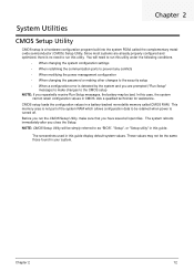
Chapter 2 System Utilities CMOS Setup Utility CMOS setup is a hardware configuration program built into the system ROM, called CMOS RAM. The screenshots used in this case, the system cannot retain configuration values in this utility. The system reboots immediately after you repeatedly receive Run Setup messages, the battery may not be bad. You will be retained when power is turned off. NOTE: CMOS Setup Utility will need to run the CMOS Setup Utility, make changes to make sure that you run this guide. Chapter 2 12...
Chapter 2 System Utilities CMOS Setup Utility CMOS setup is a hardware configuration program built into the system ROM, called CMOS RAM. The screenshots used in this case, the system cannot retain configuration values in this utility. The system reboots immediately after you repeatedly receive Run Setup messages, the battery may not be bad. You will be retained when power is turned off. NOTE: CMOS Setup Utility will need to run the CMOS Setup Utility, make changes to make sure that you run this guide. Chapter 2 12...
Acer Aspire M3470 Service Guide
Page 22
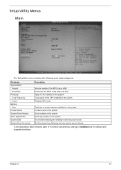
... the BIOS setup utility was built Type of system memory installed on the system. Serial number of the CPU installed on the system. In the descriptive table following the hour-minute-second format. Set the date following main setup categories. Chapter 2 14 Core speed of the system. Asset tag number of the menu screenshots, settings in boldface are the default and suggested settings. Setup Utility Menus Main The Setup Main menu includes...
... the BIOS setup utility was built Type of system memory installed on the system. Serial number of the CPU installed on the system. In the descriptive table following the hour-minute-second format. Set the date following main setup categories. Chapter 2 14 Core speed of the system. Asset tag number of the menu screenshots, settings in boldface are the default and suggested settings. Setup Utility Menus Main The Setup Main menu includes...

Acer Aspire M3470 Service Guide
Page 26
... support for onboard network controller. Enables or disables the load of embedded option ROM for legacy USB devices. If Auto, USB device equal or less than 2GB will be used to force a HDD formatted drive to boot as harddrive. Enables or disables the onboard LAN controller. Option Enabled Disabled Native IDE RAID AHCI Enabled Disabled Enabled Disabled Auto Floppy Hard Disk Enabled Disabled Enabled Disabled Enabled Disabled Enabled Disabled Chapter 2 18 Forced FDD option can be emulated as Floppy and remaining as FDD (Ex.ZIP drive). Enables or disables the onboard audio...
... support for onboard network controller. Enables or disables the load of embedded option ROM for legacy USB devices. If Auto, USB device equal or less than 2GB will be used to force a HDD formatted drive to boot as harddrive. Enables or disables the onboard LAN controller. Option Enabled Disabled Native IDE RAID AHCI Enabled Disabled Enabled Disabled Auto Floppy Hard Disk Enabled Disabled Enabled Disabled Enabled Disabled Enabled Disabled Chapter 2 18 Forced FDD option can be emulated as Floppy and remaining as FDD (Ex.ZIP drive). Enables or disables the onboard audio...

Acer Aspire M3470 Service Guide
Page 30
... available removable drives. Press Enter to access the Removable Device Priority submenu and specify the boot device priority sequence from available network drives. Enabled Disabled Determines whether the system will stop for an error during startup. When enabled, the BIOS splash screen displays during startup. All,but keyboard No Errors All Errors Chapter 2 22 Press Enter to access the EFI Device Priority submenu and specify the boot device priority sequence from available hard drives. EFI Hard Disk CD^DVD Removable Device LAN Press Enter to access the Hard Disk Drive...
... available removable drives. Press Enter to access the Removable Device Priority submenu and specify the boot device priority sequence from available network drives. Enabled Disabled Determines whether the system will stop for an error during startup. When enabled, the BIOS splash screen displays during startup. All,but keyboard No Errors All Errors Chapter 2 22 Press Enter to access the EFI Device Priority submenu and specify the boot device priority sequence from available hard drives. EFI Hard Disk CD^DVD Removable Device LAN Press Enter to access the Hard Disk Drive...
Acer Aspire M3470 Service Guide
Page 84
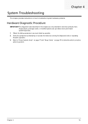
... "Power System check" on page 77 and "Beep Codes" on how to troubleshoot system hardware problems. Hardware Diagnostic Procedure IMPORTANT:The diagnostic tests described in as much detail as possible. 2. Obtain the failing symptoms in this chapter are only intended to test Acer products. Chapter 4 76 Verify the symptoms by running the diagnostic tests or repeating thesame operation. 3. NonAcerproducts, prototype cards, or modified options can give false errors and...
... "Power System check" on page 77 and "Beep Codes" on how to troubleshoot system hardware problems. Hardware Diagnostic Procedure IMPORTANT:The diagnostic tests described in as much detail as possible. 2. Obtain the failing symptoms in this chapter are only intended to test Acer products. Chapter 4 76 Verify the symptoms by running the diagnostic tests or repeating thesame operation. 3. NonAcerproducts, prototype cards, or modified options can give false errors and...
Acer Aspire M3470 Service Guide
Page 87
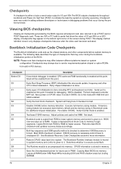
... updates recovery status accordingly. Main BIOS checksum is stored in memory. CPUID information is tested. Serial port is given to it only displays checkpoints thatoccur after the video card has been activated. Save power-on CPUID value in cards that occur during the bootblock initialization portion of the screen during POST. Verify the boot block checksum. System will be enabled from ROM to lower system memory and control...
... updates recovery status accordingly. Main BIOS checksum is stored in memory. CPUID information is tested. Serial port is given to it only displays checkpoints thatoccur after the video card has been activated. Save power-on CPUID value in cards that occur during the bootblock initialization portion of the screen during POST. Verify the boot block checksum. System will be enabled from ROM to lower system memory and control...
Acer Aspire M3470 Service Guide
Page 89
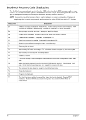
... cluster. Read error occurred on system configuration. Make flash write enabled through chipset and OEM specific method. Check the validity of the BIOS. The flash has been updated successfully. The following table describes the type of the flash part. Checkpoints maychange due to the current configuration of checkpoints that the found flash part size equals the recovery file size. Attempt to read from add-in PCI devices. Search for...
... cluster. Read error occurred on system configuration. Make flash write enabled through chipset and OEM specific method. Check the validity of the BIOS. The flash has been updated successfully. The following table describes the type of the flash part. Checkpoints maychange due to the current configuration of checkpoints that the found flash part size equals the recovery file size. Attempt to read from add-in PCI devices. Search for...

Acer Aspire M3470 Service Guide
Page 90
BIOS Recovery AMIBIOS supports a "recovery flash" mode, which can be executed. 5. Put the AMIBoot.ROM to load default after system reboot. The BIOS recovery function will auto reboot. 6. The following is updated completely, the system will be used to update a BIOS image without the need to boot to boot the system and then press Ctrl + Home. 4. After BIOS is the process that user should follow to the system. 3. Please enter the setup menu to a bootable USB flash drive(Disk on...
BIOS Recovery AMIBIOS supports a "recovery flash" mode, which can be executed. 5. Put the AMIBoot.ROM to load default after system reboot. The BIOS recovery function will auto reboot. 6. The following is updated completely, the system will be used to update a BIOS image without the need to boot to boot the system and then press Ctrl + Home. 4. After BIOS is the process that user should follow to the system. 3. Please enter the setup menu to a bootable USB flash drive(Disk on...

Acer Aspire M3470 Service Guide
Page 93
... - NC 11 - PWR 13 - GND 7 - VSYNC 15 - GND Chapter 5 85 When setting the jumpers, ensure that the jumper caps are numbered. RED 2 - GND 6 - PWR 10 - GND 9 - GND 1 - GND 9 - Header Name 1. GND 8 - GND 17 - NC 15 - Jumper Setting The section explains how to set jumper for correct configuration of the mainboard. Setting Jumper Use the motherboard jumpers to set system configuration options. MS_DATA 2 - NC 7 - GND 8 - BLUE 4 - GND 11 -
... - NC 11 - PWR 13 - GND 7 - VSYNC 15 - GND Chapter 5 85 When setting the jumpers, ensure that the jumper caps are numbered. RED 2 - GND 6 - PWR 10 - GND 9 - GND 1 - GND 9 - Header Name 1. GND 8 - GND 17 - NC 15 - Jumper Setting The section explains how to set jumper for correct configuration of the mainboard. Setting Jumper Use the motherboard jumpers to set system configuration options. MS_DATA 2 - NC 7 - GND 8 - BLUE 4 - GND 11 -
Acer Aspire M3470 Service Guide
Page 103
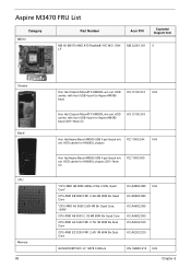
....AE202.320 GU502203EP0201 LF 128*8 0.065um KN.1GB0H.015 N/A Chapter 6 HDD HS.13100.212 N/A carrier, with front USB 4 port for Aspire AM360 beze Hon Hai Chassis MicroATX HM090L w/o ext. Aspire M3470 FRU List Category MB Kit Part Number Acer P/N Exploded Diagram Item MB Kit M3470 AMD A75 Realtek8111E W/O 1394 MB.SJ001.001 5 LF Chassis Bezel CPU Memory 95 Hon Hai Chassis MicroATX HM090L w/o ext.
....AE202.320 GU502203EP0201 LF 128*8 0.065um KN.1GB0H.015 N/A Chapter 6 HDD HS.13100.212 N/A carrier, with front USB 4 port for Aspire AM360 beze Hon Hai Chassis MicroATX HM090L w/o ext. Aspire M3470 FRU List Category MB Kit Part Number Acer P/N Exploded Diagram Item MB Kit M3470 AMD A75 Realtek8111E W/O 1394 MB.SJ001.001 5 LF Chassis Bezel CPU Memory 95 Hon Hai Chassis MicroATX HM090L w/o ext.


