Aspire L350 & Veriton 1000 Service Guide
Page 7
...System Specifications 1 Overview 1 Features 2 System Block Diagram 6 Main Board Layout 7 Your Acer Notebook tour 8 Front view 8 Rear view 9 System Peripherals 11 Mouse (PS/2 ... 21 Entering Setup 22 Product Information 23 Standard CMOS Features 24 Advanced BIOS Features 26 CPU Feature 29 Hard Disk Boot Priority 31 Network Boot Priority 32 Advanced Chipset Features 33 ...Saving 48 Chapter 3 Machine Disassembly and Replacement 49 General Information 50 Before You Begin 50 Aspire L350 Disassembly Procedure 51 Removing the Stand Assembly 51 Removing the Top Cover and Front Bezel ...
...System Specifications 1 Overview 1 Features 2 System Block Diagram 6 Main Board Layout 7 Your Acer Notebook tour 8 Front view 8 Rear view 9 System Peripherals 11 Mouse (PS/2 ... 21 Entering Setup 22 Product Information 23 Standard CMOS Features 24 Advanced BIOS Features 26 CPU Feature 29 Hard Disk Boot Priority 31 Network Boot Priority 32 Advanced Chipset Features 33 ...Saving 48 Chapter 3 Machine Disassembly and Replacement 49 General Information 50 Before You Begin 50 Aspire L350 Disassembly Procedure 51 Removing the Stand Assembly 51 Removing the Top Cover and Front Bezel ...
Aspire L350 & Veriton 1000 Service Guide
Page 8
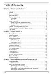
...Board 58 Removing the Front IO Assembly 60 Removing Cables/TV Tuner Board/TV Tuner Card and Wireless LAN Card . . .61 Removing the Thermal Module/CPU/Memory and the Main Board 62 Veriton 1000 Disassembly Procedure 66 Removing the Stand Assembly 66 Removing the Top Cover and Front Bezel Assembly 67... Cage Assembly 70 Removing the HDD and ODD Transfer Board 71 Removing the Front IO Assembly 72 Removing the Cables 73 Removing the Thermal Module/CPU/Memory and the Main Board 74 Chapter 4 Troubleshooting 78 Power-On Self-Test (POST 79 POST Error Messages List 85 Error Symptoms List 87 ...
...Board 58 Removing the Front IO Assembly 60 Removing Cables/TV Tuner Board/TV Tuner Card and Wireless LAN Card . . .61 Removing the Thermal Module/CPU/Memory and the Main Board 62 Veriton 1000 Disassembly Procedure 66 Removing the Stand Assembly 66 Removing the Top Cover and Front Bezel Assembly 67... Cage Assembly 70 Removing the HDD and ODD Transfer Board 71 Removing the Front IO Assembly 72 Removing the Cables 73 Removing the Thermal Module/CPU/Memory and the Main Board 74 Chapter 4 Troubleshooting 78 Power-On Self-Test (POST 79 POST Error Messages List 85 Error Symptoms List 87 ...
Aspire L350 & Veriton 1000 Service Guide
Page 10
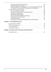
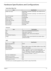
...) DVD-ROM/Combo/DVD Dual/DVD SuperMulti (w/PATA to SATA daughter board) Audio T Codec : Realtek ALC888 7.1 with S/PDIF out T Compliant with CPU Chipset T T Northbridge: Intel G965, Southbridge: Intel ICH8DH (ViiV-for Aspire L350) Northbridge: Intel Q965, Southbridge: Intel ICH8DO (vPro-for Veriton 1000) Memory T T T T Socket Type: DDR II so-DIMM,1.8 Voltage Socket Quantity...
...) DVD-ROM/Combo/DVD Dual/DVD SuperMulti (w/PATA to SATA daughter board) Audio T Codec : Realtek ALC888 7.1 with S/PDIF out T Compliant with CPU Chipset T T Northbridge: Intel G965, Southbridge: Intel ICH8DH (ViiV-for Aspire L350) Northbridge: Intel Q965, Southbridge: Intel ICH8DO (vPro-for Veriton 1000) Memory T T T T Socket Type: DDR II so-DIMM,1.8 Voltage Socket Quantity...
Aspire L350 & Veriton 1000 Service Guide
Page 12
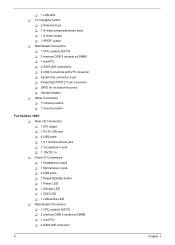
T 1 LAN LED T TV Daughter board T 2 Antenna input T 1 S-video/composite/stereo input T 1 S-video output T 1 SPDIF output T Main Board Connectors T 1 CPU socket LGA775 T 2 memory DDR II sockets so-DIMM T 1 mini-PCI T 2 SATA IDE connectors T 2 USB connectors with 2*5 connector T System fan connector 4-pin T Power/LED... Connectors T 1 Headphone output T 1 Microphone in jack T 4 USB ports T 1 Power/Standby button T 1 Power LED T 1 Storage LED T 1 ODD LED T 1 LAN active LED T Main Board Connectors T 1 CPU socket LGA775 T 2 memory DDR II socket so-DIMM T 1 mini-PCI T 2 SATA IDE connector 4 Chapter 1
T 1 LAN LED T TV Daughter board T 2 Antenna input T 1 S-video/composite/stereo input T 1 S-video output T 1 SPDIF output T Main Board Connectors T 1 CPU socket LGA775 T 2 memory DDR II sockets so-DIMM T 1 mini-PCI T 2 SATA IDE connectors T 2 USB connectors with 2*5 connector T System fan connector 4-pin T Power/LED... Connectors T 1 Headphone output T 1 Microphone in jack T 4 USB ports T 1 Power/Standby button T 1 Power LED T 1 Storage LED T 1 ODD LED T 1 LAN active LED T Main Board Connectors T 1 CPU socket LGA775 T 2 memory DDR II socket so-DIMM T 1 mini-PCI T 2 SATA IDE connector 4 Chapter 1

Aspire L350 & Veriton 1000 Service Guide
Page 15
... 8 LAN_USB2 LAN and USB*2 Connector 9 USB2 USB*2 Connector 10 OBR 11 CPU_FAN 12 INTRUSION 13 CPU_SOCKET 14 MINI_PCI One Bottom Recovery header CPU Fan Connector Case Open header AMD M-2 CPU Socket Mini-PCI Connector 15 C51 16 MCP51 17 COMS_BAT Nvidia C51 NorthBridge Nvidia MCP51 SouthBridge COMS Battery Holder 18 CLS_CMOS Clear...
... 8 LAN_USB2 LAN and USB*2 Connector 9 USB2 USB*2 Connector 10 OBR 11 CPU_FAN 12 INTRUSION 13 CPU_SOCKET 14 MINI_PCI One Bottom Recovery header CPU Fan Connector Case Open header AMD M-2 CPU Socket Mini-PCI Connector 15 C51 16 MCP51 17 COMS_BAT Nvidia C51 NorthBridge Nvidia MCP51 SouthBridge COMS Battery Holder 18 CLS_CMOS Clear...
Aspire L350 & Veriton 1000 Service Guide
Page 21
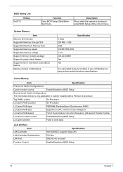
... Controller Memory Controller SATA/P-IDE Controller RJ45 Controller Audio Controller VGA Controller Specification Northbridge: Intel G965, Southbridge: Intel ICH8DH (ViiV-for Aspire L350) Northbridge: Intel Q965, Southbridge: Intel ICH8DO (vPro-for Veriton 1000) ITE IT8718F Intel 82566DM Intel G965 Intel ICH8 Intel 82566DC/...Slot Speed Front Side Bus Frequency Voltage Specification Intel Conroe (E6700/E6600/E6400/E6300) Intel socket T (LGA775) Depends on CPU, which is local configured 1066MHz Processor voltage can be detected by any system without setting any jumper BIOS Item BIOS code ...
... Controller Memory Controller SATA/P-IDE Controller RJ45 Controller Audio Controller VGA Controller Specification Northbridge: Intel G965, Southbridge: Intel ICH8DH (ViiV-for Aspire L350) Northbridge: Intel Q965, Southbridge: Intel ICH8DO (vPro-for Veriton 1000) ITE IT8718F Intel 82566DM Intel G965 Intel ICH8 Intel 82566DC/...Slot Speed Front Side Bus Frequency Voltage Specification Intel Conroe (E6700/E6600/E6400/E6300) Intel socket T (LGA775) Depends on CPU, which is local configured 1066MHz Processor voltage can be detected by any system without setting any jumper BIOS Item BIOS code ...
Aspire L350 & Veriton 1000 Service Guide
Page 22
... RAM Location On Processor L2 Cache RAM Location On Processor L2 Cache RAM type PBSRAM (Pipelined-burst Synchronous RAM) L2 Cache RAM size Depends on CPU, which is only applicable to enter BIOS Setup Utility or boot menu. Cache Memory Item Specification First-Level Cache Configurations Cache function control Enable/Disable...
... RAM Location On Processor L2 Cache RAM Location On Processor L2 Cache RAM type PBSRAM (Pipelined-burst Synchronous RAM) L2 Cache RAM size Depends on CPU, which is only applicable to enter BIOS Setup Utility or boot menu. Cache Memory Item Specification First-Level Cache Configurations Cache function control Enable/Disable...

Aspire L350 & Veriton 1000 Service Guide
Page 27
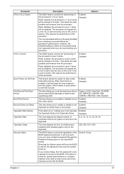
...for ATA standard interface). Suspend Mode T Independent power management timer (2-120 minutes, time step=10 minutes) or pushing external switch button. T CPU goes into power saving mode. T On board device configuration support. T Hard disk drive goes into Standby mode (for ATA standard interface)....Grant State. T Ultra I/O and VGA chip go into SMM. T Resume recovery time: 3-5 sec. T Resume recovery time: 7-10 sec. T CPU asserts STPCLK# and goes into SLEEP mode (for hard disk drive devices (0-15 minutes, time step=1 minute). Power Management Function (ACPI support function)...
...for ATA standard interface). Suspend Mode T Independent power management timer (2-120 minutes, time step=10 minutes) or pushing external switch button. T CPU goes into power saving mode. T On board device configuration support. T Hard disk drive goes into Standby mode (for ATA standard interface)....Grant State. T Ultra I/O and VGA chip go into SMM. T Resume recovery time: 3-5 sec. T Resume recovery time: 7-10 sec. T CPU asserts STPCLK# and goes into SLEEP mode (for hard disk drive devices (0-15 minutes, time step=1 minute). Power Management Function (ACPI support function)...

Aspire L350 & Veriton 1000 Service Guide
Page 34
...:Value F10:Save ESC:Exit F1:General Help F5:Previous Values F7:Default Settings Parameter CPU Feature Hard Disk Boot Priority Network Boot Priority Description Press [Enter] to see CPU feature Press [Enter] to enter the sub menu to select network boot device priority....to move it down the list. Award BIOS CMOS Setup Utility Advanced BIOS Features X CPU Feature [Press Enter] X Hard Disk Boot Priority [Press Enter] X Network Boot Priority [Press Enter] CPU L1 & L2 Cache [Enabled] CPU L3 Cache [Enabled] Quick Power On Self Test [Enabled] First Boot Device [N/A] ...
...:Value F10:Save ESC:Exit F1:General Help F5:Previous Values F7:Default Settings Parameter CPU Feature Hard Disk Boot Priority Network Boot Priority Description Press [Enter] to see CPU feature Press [Enter] to enter the sub menu to select network boot device priority....to move it down the list. Award BIOS CMOS Setup Utility Advanced BIOS Features X CPU Feature [Press Enter] X Hard Disk Boot Priority [Press Enter] X Network Boot Priority [Press Enter] CPU L1 & L2 Cache [Enabled] CPU L3 Cache [Enabled] Quick Power On Self Test [Enabled] First Boot Device [N/A] ...
Aspire L350 & Veriton 1000 Service Guide
Page 35
... to ask for system administrators or computer resellers who need to the BIOS. Selecting the System option will be allowed to function. Parameter CPU L1 & L2 Cache CPU L3 Cache Quick Power On Self Test First/Second/Third Boot Device Boot Other Device Boot Up NumLock Status Typematic Rate Setting Typematic Rate...
... to ask for system administrators or computer resellers who need to the BIOS. Selecting the System option will be allowed to function. Parameter CPU L1 & L2 Cache CPU L3 Cache Quick Power On Self Test First/Second/Third Boot Device Boot Other Device Boot Up NumLock Status Typematic Rate Setting Typematic Rate...
Aspire L350 & Veriton 1000 Service Guide
Page 37
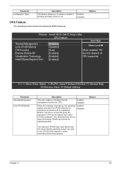
...] [Disabled] Menu Level X C1E Function [Auto] When enabled, TM Execute Disable Bit [Enabled] function depend on Virtualization Technology [Enabled] CPU supported Intel(R)SpeedStep(tm)Tech. [Enabled] KLIJ :Move Enter: Select +/-/PU/PD :Value F10:Save ESC:Exit F1:General Help F5:Previous... booted up, the operating system executes the CPUID instruction to enable or disable if showing summary screen or not Enabled Disabled CPU Feature The following screen shows the Advanced BIOS Features: Options Phoenix - Options Chapter 2 29 Parameter Configuration Table Description This ...
...] [Disabled] Menu Level X C1E Function [Auto] When enabled, TM Execute Disable Bit [Enabled] function depend on Virtualization Technology [Enabled] CPU supported Intel(R)SpeedStep(tm)Tech. [Enabled] KLIJ :Move Enter: Select +/-/PU/PD :Value F10:Save ESC:Exit F1:General Help F5:Previous... booted up, the operating system executes the CPUID instruction to enable or disable if showing summary screen or not Enabled Disabled CPU Feature The following screen shows the Advanced BIOS Features: Options Phoenix - Options Chapter 2 29 Parameter Configuration Table Description This ...

Aspire L350 & Veriton 1000 Service Guide
Page 44
... of graphics memory but when the need for optimal balance between the graphics processor and the operating system. When set this is shared by both CPU and graphics processor. Setting it is not in use. This ensures that controls all this BIOS feature to either system or graphics processor. Parameter DVMT...
... of graphics memory but when the need for optimal balance between the graphics processor and the operating system. When set this is shared by both CPU and graphics processor. Setting it is not in use. This ensures that controls all this BIOS feature to either system or graphics processor. Parameter DVMT...

Aspire L350 & Veriton 1000 Service Guide
Page 45
... modes. But if you have any point in time. When set the maximum amount of system memory, it also reduces the system's performance by both CPU and graphics processor. This setting works well in . It allows you to set to 128MB, up to 64MB. Generally, you restrict the amount of DVMT...
... modes. But if you have any point in time. When set the maximum amount of system memory, it also reduces the system's performance by both CPU and graphics processor. This setting works well in . It allows you to set to 128MB, up to 64MB. Generally, you restrict the amount of DVMT...

Aspire L350 & Veriton 1000 Service Guide
Page 48
... However, it only if you are using an older operating system like DOS or Windows 95/98 do not support this state, no system context (CPU or chipset) is a low power state. Older operating systems like DOS or Windows 95/98. It is only supported by Alarm [Disabled] x Date(of computer...
... However, it only if you are using an older operating system like DOS or Windows 95/98 do not support this state, no system context (CPU or chipset) is a low power state. Older operating systems like DOS or Windows 95/98. It is only supported by Alarm [Disabled] x Date(of computer...
Aspire L350 & Veriton 1000 Service Guide
Page 51
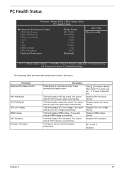
...status automatically. The system detects system fan speed status automatically This field displays CPU core voltage. The system detects CPU core voltage automatically. The system detects CPU tempature automatically. Displays CPU fan speed directly. Displays CPU tempature. 90 ° C/194 ° F Disabled Chapter 2 43 ...Settings The following table describes the parameters found in this menu: Parameter Advanced Fan Speed Control CPU FAN Speed SYS FAN Speed CPU core voltage DIMM voltage CPU Tempature Shutdown Tempature Description Press [Enter] to enter the sub menu to see advanced fan...
...status automatically. The system detects system fan speed status automatically This field displays CPU core voltage. The system detects CPU core voltage automatically. The system detects CPU tempature automatically. Displays CPU fan speed directly. Displays CPU tempature. 90 ° C/194 ° F Disabled Chapter 2 43 ...Settings The following table describes the parameters found in this menu: Parameter Advanced Fan Speed Control CPU FAN Speed SYS FAN Speed CPU core voltage DIMM voltage CPU Tempature Shutdown Tempature Description Press [Enter] to enter the sub menu to see advanced fan...

Aspire L350 & Veriton 1000 Service Guide
Page 52
...the PCI bus. Enabled Disabled 44 Chapter 2 AwardBIOS CMOS Setup Utility Frequency Control Auto Detect PCI Clk Spread Spectrum [Enabled] [Enabled] Item Help CPU Host/SRC/PCI Clock [Enabled] Menu Level X KLIJ :Move Enter: Select +/-/PU/PD :Value F10:Save ESC:Exit F1:General Help F5:...Previous Values F7:Default Settings Parameter Auto Detect PCI Clk Spread Spectrum CPU Host/SRC/PCI Clock Description To reduce the occurrence of electromagnetic interference (EMI), the BIOS detects the presence or absence of components in DIMM...
...the PCI bus. Enabled Disabled 44 Chapter 2 AwardBIOS CMOS Setup Utility Frequency Control Auto Detect PCI Clk Spread Spectrum [Enabled] [Enabled] Item Help CPU Host/SRC/PCI Clock [Enabled] Menu Level X KLIJ :Move Enter: Select +/-/PU/PD :Value F10:Save ESC:Exit F1:General Help F5:...Previous Values F7:Default Settings Parameter Auto Detect PCI Clk Spread Spectrum CPU Host/SRC/PCI Clock Description To reduce the occurrence of electromagnetic interference (EMI), the BIOS detects the presence or absence of components in DIMM...

Aspire L350 & Veriton 1000 Service Guide
Page 70
Disconnect the antennae and detach the TV tuner board. 4. Removing the Thermal Module/CPU/Memory and the Main 62 Chapter 3 Pop out the TV tuner card and detach the wireless LAN card from the main board. 3.
Disconnect the antennae and detach the TV tuner board. 4. Removing the Thermal Module/CPU/Memory and the Main 62 Chapter 3 Pop out the TV tuner card and detach the wireless LAN card from the main board. 3.

Aspire L350 & Veriton 1000 Service Guide
Page 71
Board 1. Then detach the fan from the socket. Release the CPU lock and remove the CPU from the system. 3. Remove the four screws fastening the heat sink to the system fan and the heat sink. 4. Remove the four screws holding the system fan on the headline refers to the main board. (Follow the order indicating by the numbers).Then detach the heat sink from the main board. 41 23 NOTE: The thermal module on the rear side. Chapter 3 63 Disconnect the system fan power cable. 2.
Board 1. Then detach the fan from the socket. Release the CPU lock and remove the CPU from the system. 3. Remove the four screws fastening the heat sink to the system fan and the heat sink. 4. Remove the four screws holding the system fan on the headline refers to the main board. (Follow the order indicating by the numbers).Then detach the heat sink from the main board. 41 23 NOTE: The thermal module on the rear side. Chapter 3 63 Disconnect the system fan power cable. 2.

Aspire L350 & Veriton 1000 Service Guide
Page 82
Disconnect the system fan power cable. 2. Then detach the fan from the main board and remove the cable. Removing the Thermal Module/CPU/Memory and the Main Board 1. 3. Remove the four screws holding the system fan on the rear side. Disconnect the power switch cable from the system. 74 Chapter 3
Disconnect the system fan power cable. 2. Then detach the fan from the main board and remove the cable. Removing the Thermal Module/CPU/Memory and the Main Board 1. 3. Remove the four screws holding the system fan on the rear side. Disconnect the power switch cable from the system. 74 Chapter 3

Aspire L350 & Veriton 1000 Service Guide
Page 83
Remove the four screws fastening the heat sink to the system fan and the heat sink. 4. Release the CPU lock and remove the CPU from the main board. 41 23 NOTE: The thermal module on the headline refers to the main board. (Follow the order indicating by the numbers).Then detach the heat sink from the socket. 5. Pop out the memories and remove them from the main board. Chapter 3 75 3.
Remove the four screws fastening the heat sink to the system fan and the heat sink. 4. Release the CPU lock and remove the CPU from the main board. 41 23 NOTE: The thermal module on the headline refers to the main board. (Follow the order indicating by the numbers).Then detach the heat sink from the socket. 5. Pop out the memories and remove them from the main board. Chapter 3 75 3.

