Service Guide
Page 7
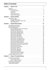
... Hard Disk Drive 32 Removing the Left Side Panel 34 Removing the Right Side Panel 35 Removing the Front Bezel 36 Removing the Optical Drive 38 Removing the Video Cards 39 Removing the TV Tuner Card 41 Removing the Card Reader Drive 42 Removing the Card Reader Board 44 Removing the Backplane Board 46 Removing the Memory Modules 48 Removing the Liquid Cooler Fan Assembly 49 Removing the Fan from the Liquid Cooler 51 Removing the Processor 52 Removing the Power Supply 54 Removing the HDD Fan 56 Removing the Top Cover...
... Hard Disk Drive 32 Removing the Left Side Panel 34 Removing the Right Side Panel 35 Removing the Front Bezel 36 Removing the Optical Drive 38 Removing the Video Cards 39 Removing the TV Tuner Card 41 Removing the Card Reader Drive 42 Removing the Card Reader Board 44 Removing the Backplane Board 46 Removing the Memory Modules 48 Removing the Liquid Cooler Fan Assembly 49 Removing the Fan from the Liquid Cooler 51 Removing the Processor 52 Removing the Power Supply 54 Removing the HDD Fan 56 Removing the Top Cover...
Service Guide
Page 8
Chapter 5 System Block Diagram and Board Layout 79 Board Layout 80 Mainboard 80 Back Panel I/O 81 System Switches and Jumpers 83 Serial ATA Connectors 83 Fan Power Connectors 83 IEEE 1394 Connector 84 Front Panel Connector 84 Front USB Connector 85 Chassis Intrusion Connector 85 Front Panel Auido Connector 85 Power Connectors 86 CMOS Reset Button 87 Chapter 6 FRU (Field Replaceable Unit) List 89 Aspire G7710 Series Exploded Diagram 90 Aspire G7710 Series 92 Appendix A Technical Specifications 97 Appendix B Test Compatible Components 101 viii
Chapter 5 System Block Diagram and Board Layout 79 Board Layout 80 Mainboard 80 Back Panel I/O 81 System Switches and Jumpers 83 Serial ATA Connectors 83 Fan Power Connectors 83 IEEE 1394 Connector 84 Front Panel Connector 84 Front USB Connector 85 Chassis Intrusion Connector 85 Front Panel Auido Connector 85 Power Connectors 86 CMOS Reset Button 87 Chapter 6 FRU (Field Replaceable Unit) List 89 Aspire G7710 Series Exploded Diagram 90 Aspire G7710 Series 92 Appendix A Technical Specifications 97 Appendix B Test Compatible Components 101 viii
Service Guide
Page 9
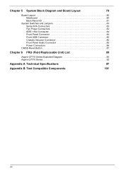
... • BD/HD DVD reader + SuperMulti DVD burner • Super-Multi DVD drive (with Labelflash technology) • Four 3.5" easy-swap HDD drive bays • 4 HDD cage • Easy-swap HDD cage with hot-swap Networking • Gigabit Ethernet, Wake-on LAN ready (dual LAN support) • Modem: 56K ITU V.92, Wake-on the model purchased. The exact configuration of the computer's many feature: NOTE: The feature listed in this section...
... • BD/HD DVD reader + SuperMulti DVD burner • Super-Multi DVD drive (with Labelflash technology) • Four 3.5" easy-swap HDD drive bays • 4 HDD cage • Easy-swap HDD cage with hot-swap Networking • Gigabit Ethernet, Wake-on LAN ready (dual LAN support) • Modem: 56K ITU V.92, Wake-on the model purchased. The exact configuration of the computer's many feature: NOTE: The feature listed in this section...

Service Guide
Page 13
Front Panel Item 1 2 3 4 5 6 7 8 9 10 11 12 13 14 Icon Component USB 2.0 ports Microphone/speaker-out/line-in jack Headphone/line-out jack Power button/power indicator Optical disk drives XD (eXtreme Digital) slot USB 2.0 port IEEE 1394 port (4-pin) CFI/II (CompactFlash Type I/II) slot Drive bay door Easy-swap hard disk drives (1-4) MS/MS Pro (Memory Stick/Memory Stick Pro Duo) slot SD/MMC (SecureDigital/MultimediaCard) slot Optical disk drive eject buttons Chapter 1 5
Front Panel Item 1 2 3 4 5 6 7 8 9 10 11 12 13 14 Icon Component USB 2.0 ports Microphone/speaker-out/line-in jack Headphone/line-out jack Power button/power indicator Optical disk drives XD (eXtreme Digital) slot USB 2.0 port IEEE 1394 port (4-pin) CFI/II (CompactFlash Type I/II) slot Drive bay door Easy-swap hard disk drives (1-4) MS/MS Pro (Memory Stick/Memory Stick Pro Duo) slot SD/MMC (SecureDigital/MultimediaCard) slot Optical disk drive eject buttons Chapter 1 5

Service Guide
Page 14
Rear Panel Item 1 2 3 4 5 6 7 8 9 10 11 12 13 14 15 16 17 18 19 20 Icon 6 Component Power supply PS2 mouse port System fan Network ports Rear speaker jack Center speaker/subwoofer jack Expansion slot locks S-video port DVI port Audio-in/line-in jack Headphone/line-out/front speaker jack Microphone/line-in jack S/PDIF jack USB 2.0 ports IEEE 1394 port (6-pin) eSATA (External Serial Advanced Technology Attachment) ports Clear CMOS button PS2 keyboard port Power connector Main power switch Chapter 1
Rear Panel Item 1 2 3 4 5 6 7 8 9 10 11 12 13 14 15 16 17 18 19 20 Icon 6 Component Power supply PS2 mouse port System fan Network ports Rear speaker jack Center speaker/subwoofer jack Expansion slot locks S-video port DVI port Audio-in/line-in jack Headphone/line-out/front speaker jack Microphone/line-in jack S/PDIF jack USB 2.0 ports IEEE 1394 port (6-pin) eSATA (External Serial Advanced Technology Attachment) ports Clear CMOS button PS2 keyboard port Power connector Main power switch Chapter 1

Service Guide
Page 17
... power is no need to run this utility under the following conditions. • When changing the system configuration settings • When redefining the communication ports to prevent any conflicts • When modifying the power management configuration • When changing the password or making other changes to run this utility. The system reboots immediately after you have saved all open files. Chapter 2 System Utilities CMOS Setup Utility CMOS setup is a hardware configuration program built into the system ROM, called CMOS RAM...
... power is no need to run this utility under the following conditions. • When changing the system configuration settings • When redefining the communication ports to prevent any conflicts • When modifying the power management configuration • When changing the password or making other changes to run this utility. The system reboots immediately after you have saved all open files. Chapter 2 System Utilities CMOS Setup Utility CMOS setup is a hardware configuration program built into the system ROM, called CMOS RAM...

Service Guide
Page 21
.../SATA/E-SATA connectors. & Serial-ATA 1~6 channel & E-SATA 1/2 Halt On Determines whether the system will stop for the IDE/SATA/E-SATA drive. is necessary. Primary Master/Slave Press Enter to view detailed device information connected to the device occurs one sector at a time if the device supports it. For drivers with more than 504 MB, LBA mode is a utility that monitors the hard disk's condition. S.M.A.R.T. Enables or disables the 32-bit data transfer mode. Option...
.../SATA/E-SATA connectors. & Serial-ATA 1~6 channel & E-SATA 1/2 Halt On Determines whether the system will stop for the IDE/SATA/E-SATA drive. is necessary. Primary Master/Slave Press Enter to view detailed device information connected to the device occurs one sector at a time if the device supports it. For drivers with more than 504 MB, LBA mode is a utility that monitors the hard disk's condition. S.M.A.R.T. Enables or disables the 32-bit data transfer mode. Option...
Service Guide
Page 22
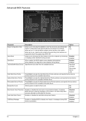
... Protection Enables or disables the boot sector virus protection feature. Disabled Enabled Hard Disk Write Protect Enables or disables the hard disk write protect feature. When disabled, the diagnostic screen displays during USB device enumeration. If enabled, BIOS will show a warning message on state for boot if the system has a PnP OS. Yes When set to display error beeps or messages during startup. Enabled Disabled 1st/2nd/3rd/4th Boot Device Specifies the boot order from available CD/DVD drives. Optical Disk Drive Priority Press Enter...
... Protection Enables or disables the boot sector virus protection feature. Disabled Enabled Hard Disk Write Protect Enables or disables the hard disk write protect feature. When disabled, the diagnostic screen displays during USB device enumeration. If enabled, BIOS will show a warning message on state for boot if the system has a PnP OS. Yes When set to display error beeps or messages during startup. Enabled Disabled 1st/2nd/3rd/4th Boot Device Specifies the boot order from available CD/DVD drives. Optical Disk Drive Priority Press Enter...
Service Guide
Page 24
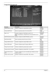
...or disables support for the onboard SATA. Note: This parameter is configurable only if the SATA Mode is set to 6. Enables or disables the ESATA RAID/IDE controller. Option Enabled Disabled RAID Native IDE Disabled Enabled Disabled Enabled IDE RAID Enabled Disabled Enabled Disabled Enabled Disabled Enabled Disabled Disabled Enabled Enabled Disabled 16 Chapter 2 Onboard SATA Mode Select an operating mode for legacy USB devices. Onboard LAN1/2 Option ROM Onboard 1394 Controller Enables or disables the load of embedded option ROM for the ATA controller. Onboard Audio Controller...
...or disables support for the onboard SATA. Note: This parameter is configurable only if the SATA Mode is set to 6. Enables or disables the ESATA RAID/IDE controller. Option Enabled Disabled RAID Native IDE Disabled Enabled Disabled Enabled IDE RAID Enabled Disabled Enabled Disabled Enabled Disabled Enabled Disabled Disabled Enabled Enabled Disabled 16 Chapter 2 Onboard SATA Mode Select an operating mode for legacy USB devices. Onboard LAN1/2 Option ROM Onboard 1394 Controller Enables or disables the load of embedded option ROM for the ATA controller. Onboard Audio Controller...

Service Guide
Page 25
... from a power saving mode through a Power Management Event (PME). Enables or disables to reboot after a power failure or interrupt occurs. Option S3 (STR) S1 (POS) Enable Disabled Disabled Enabled Enabled Disabled Enabled Disabled Enabled Disabled Enabled Disabled Enabled Disabled Off On Last State Chapter 2 17 If enabled, press any key or click the mouse will wake system from a power saving mode using a PS2 mouse. Enables for disables Deep Power off function (deep power off mode reserve only certain power for the CMOS battery and remove other power source such as CPU, memory, WOL...
... from a power saving mode through a Power Management Event (PME). Enables or disables to reboot after a power failure or interrupt occurs. Option S3 (STR) S1 (POS) Enable Disabled Disabled Enabled Enabled Disabled Enabled Disabled Enabled Disabled Enabled Disabled Enabled Disabled Off On Last State Chapter 2 17 If enabled, press any key or click the mouse will wake system from a power saving mode using a PS2 mouse. Enables for disables Deep Power off function (deep power off mode reserve only certain power for the CMOS battery and remove other power source such as CPU, memory, WOL...
Service Guide
Page 28
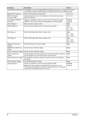
... Memory Reference Voltage Set the NB memory reference voltage. Auto DIMM Memory Reference Set the memory reference voltage. Parameter Description Option Adjust DRAM Configuration Press Enter to access the Adjust DRAM Configuration submenu to lock up. A slight jitter can introduce a temporary boost in clock speed causing the overclocked processor to override the memory's Serial Presence Detect (SPD) settings by manually entering values for DRAM timings. Enabled Disabled CPU Voltage (V) Select processor voltage control...
... Memory Reference Voltage Set the NB memory reference voltage. Auto DIMM Memory Reference Set the memory reference voltage. Parameter Description Option Adjust DRAM Configuration Press Enter to access the Adjust DRAM Configuration submenu to lock up. A slight jitter can introduce a temporary boost in clock speed causing the overclocked processor to override the memory's Serial Presence Detect (SPD) settings by manually entering values for DRAM timings. Enabled Disabled CPU Voltage (V) Select processor voltage control...
Service Guide
Page 29
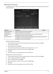
... keys to select Change Supervisor Password menu then press Enter. 2. Select Yes to save the new password and close the Setup Utility. Use the up access passwords. User password is set. Changing the supervisor password 1. Type a new password then press Enter. 4. Chapter 2 21 Supervisor password prevents unauthorized access to change the Supervisor password. User password is available only when a Supervisor password is used to control entry access to change the User password. A password box will appear. 2. Press Enter to the BIOS Setup Utility. Retype the password...
... keys to select Change Supervisor Password menu then press Enter. 2. Select Yes to save the new password and close the Setup Utility. Use the up access passwords. User password is set. Changing the supervisor password 1. Type a new password then press Enter. 4. Chapter 2 21 Supervisor password prevents unauthorized access to change the Supervisor password. User password is available only when a Supervisor password is used to control entry access to change the User password. A password box will appear. 2. Press Enter to the BIOS Setup Utility. Retype the password...

Service Guide
Page 30
... the new password and close the Setup Utility. Type the original password then press Enter. 3. Select Yes to select Set User Password menu then press Enter. 2. Removing a user password 1. Use the up /down arrow keys to select Set User Password menu then press Enter. Use the up /down arrow keys to save the new password and close the Setup Utility. Enter the current password then press Enter. 3. Press Enter twice without entering anything in the password fields. Removing a supervisor password 1. Setting a user password 1. Type a password then press Enter. Use the...
... the new password and close the Setup Utility. Type the original password then press Enter. 3. Select Yes to select Set User Password menu then press Enter. 2. Removing a user password 1. Use the up /down arrow keys to select Set User Password menu then press Enter. Use the up /down arrow keys to save the new password and close the Setup Utility. Enter the current password then press Enter. 3. Press Enter twice without entering anything in the password fields. Removing a supervisor password 1. Setting a user password 1. Type a password then press Enter. Use the...
Service Guide
Page 37
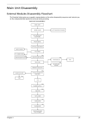
... RIGHT SIDE PANEL FRONT BEZEL OPTICAL DISK DRIVE PCI CARDS Bx2 CARD READER DRIVE HDD CAGE MEMORY MODULES Ex4 LIQUID COOLER FAN ASSEMBLY CPU Gx4 POWER SUPPLY Hx4 HDD FAN TOP COVER Ix2 USB BOARD Jx6 MAINBOARD FRONT AND REAR FOOT STANDS Ax4 HDD MODULE Dx2 BACKPLANE BOARD HDD Chapter 3 29 Main Unit Disassembly External Modules Disassembly Flowchart The flowchart below gives you a graphic representation on the entire disassembly sequence and instructs you on the components that need to be removed during servicing.
... RIGHT SIDE PANEL FRONT BEZEL OPTICAL DISK DRIVE PCI CARDS Bx2 CARD READER DRIVE HDD CAGE MEMORY MODULES Ex4 LIQUID COOLER FAN ASSEMBLY CPU Gx4 POWER SUPPLY Hx4 HDD FAN TOP COVER Ix2 USB BOARD Jx6 MAINBOARD FRONT AND REAR FOOT STANDS Ax4 HDD MODULE Dx2 BACKPLANE BOARD HDD Chapter 3 29 Main Unit Disassembly External Modules Disassembly Flowchart The flowchart below gives you a graphic representation on the entire disassembly sequence and instructs you on the components that need to be removed during servicing.
Service Guide
Page 75
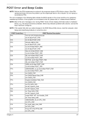
... after you make changes in the computer. POST Error and Beep Codes NOTE: Perform the FRU replacement or actions in the sequence shown in FRU/Action column, if the FRU replacement does not solve the problem, put the original part back in the BIOS Setup Utility menus, reset the computer, enter Setup and install Setup defaults or correct the error. NOTE: Most of memory installed. Others may indicate a problem with a device, such as...
... after you make changes in the computer. POST Error and Beep Codes NOTE: Perform the FRU replacement or actions in the sequence shown in FRU/Action column, if the FRU replacement does not solve the problem, put the original part back in the BIOS Setup Utility menus, reset the computer, enter Setup and install Setup defaults or correct the error. NOTE: Most of memory installed. Others may indicate a problem with a device, such as...

Service Guide
Page 79
... Check Install POST INT 09h Handler_FAR far Init USB HC Validate Attached USB Mass Devices far Init USB HC By Pass DMAC8237Test_FAR DMAC8237Test_FAR Init DMAC8237_FAR Global Device Init At Mid POST_FAR Init RTC_FAR Global Device Init At Mid POST_FAR OEMBOARD_B_Init System RAM_FAR Init System RAM_FAR Check Memory Above 4GB_FAR Init System RAM_FAR Display 4GB Plus System RAM Size_FAR Display System RAM Size_FAR Display...
... Check Install POST INT 09h Handler_FAR far Init USB HC Validate Attached USB Mass Devices far Init USB HC By Pass DMAC8237Test_FAR DMAC8237Test_FAR Init DMAC8237_FAR Global Device Init At Mid POST_FAR Init RTC_FAR Global Device Init At Mid POST_FAR OEMBOARD_B_Init System RAM_FAR Init System RAM_FAR Check Memory Above 4GB_FAR Init System RAM_FAR Display 4GB Plus System RAM Size_FAR Display System RAM Size_FAR Display...

Service Guide
Page 89
... Line-Out Clear CMOS Button USB Ports Optical Mic S/PDIF-Out Code Mouse Keyboard 1394 port Optical S/PDIF-out jack eSATA ports Clear CMOS Button LAN Jacks USB ports CS-Out RS-Out SS-Out Line-In Color Green Purple Blue Orange Black Blue Blue Line-Out Mic Green Pink Component PS/2 mouse port PS/2 keyboard port IEEE 1394 port (6-pin) S/PDIF port eSATA ports CMOS reset button Network ports USB ports Center speaker/subwoofer jack (in 5.1/7.1 channel mode) Rear speaker/surround out jack (in 4/5.1/7.1 channel mode) Side speaker/surround out...
... Line-Out Clear CMOS Button USB Ports Optical Mic S/PDIF-Out Code Mouse Keyboard 1394 port Optical S/PDIF-out jack eSATA ports Clear CMOS Button LAN Jacks USB ports CS-Out RS-Out SS-Out Line-In Color Green Purple Blue Orange Black Blue Blue Line-Out Mic Green Pink Component PS/2 mouse port PS/2 keyboard port IEEE 1394 port (6-pin) S/PDIF port eSATA ports CMOS reset button Network ports USB ports Center speaker/subwoofer jack (in 5.1/7.1 channel mode) Rear speaker/surround out jack (in 4/5.1/7.1 channel mode) Side speaker/surround out...

Service Guide
Page 90
... be connected to the +12V; You may occur during transmission. the black wire is a high-speed Serial ATA interface port. Otherwise, data loss may select how many percentage of speed for CPUFAN. Fan Power Connectors The fan power connectors (CPUFAN and SYSFAN1-5) support system cooling fan with 3 or 4 pins are supported by ICH10R SATA1_3 SATA2_4 SATA5_6 IMPORTANT:Please do not fold the Serial ATA cable into 90-degree angle. CONTROL...
... be connected to the +12V; You may occur during transmission. the black wire is a high-speed Serial ATA interface port. Otherwise, data loss may select how many percentage of speed for CPUFAN. Fan Power Connectors The fan power connectors (CPUFAN and SYSFAN1-5) support system cooling fan with 3 or 4 pins are supported by ICH10R SATA1_3 SATA2_4 SATA5_6 IMPORTANT:Please do not fold the Serial ATA cable into 90-degree angle. CONTROL...

Service Guide
Page 103
Appendix A Technical Specifications This section provides technical specifications for more informtion. AVLC Processor Item Specification Type Intel Core 2 Extreme Model Number QX9650 Core Quad (45 nm) L2 Cache Size (MB) 12 Clock Speed (GHz) 3 Front Side Bus (MHz) 1333 Frequency (MHz) 3000 Socket LGA 775 Clock Multiplier 9x Voltage (V) 0.85 - 1.3625 Thermal Design 130 Power (W) System Board Major Chips Q9300 Quad (45 nm...
Appendix A Technical Specifications This section provides technical specifications for more informtion. AVLC Processor Item Specification Type Intel Core 2 Extreme Model Number QX9650 Core Quad (45 nm) L2 Cache Size (MB) 12 Clock Speed (GHz) 3 Front Side Bus (MHz) 1333 Frequency (MHz) 3000 Socket LGA 775 Clock Multiplier 9x Voltage (V) 0.85 - 1.3625 Thermal Design 130 Power (W) System Board Major Chips Q9300 Quad (45 nm...

Service Guide
Page 105
.../DL) 10x / 8x / 12x / 8x max. CAV DVD-R DL 6x max. CAV CD-R/RW/ROM 32x / 24x / 32x max. IEEE 1394 Interface Item IEEE 1394 controller Connectors Optical Drive BD-R Item Vendor Model name Drive type Write Speed Read Speed Data Transfer Rate Access Time Buffer Size Interface Type Specification VIA 6315N 1394a controller 1 rear 6pin IEEE1394 port 1 2x5pin on board jumper Specification HLDS GGW-H20N BD-R GGC-H20N BD...
.../DL) 10x / 8x / 12x / 8x max. CAV DVD-R DL 6x max. CAV CD-R/RW/ROM 32x / 24x / 32x max. IEEE 1394 Interface Item IEEE 1394 controller Connectors Optical Drive BD-R Item Vendor Model name Drive type Write Speed Read Speed Data Transfer Rate Access Time Buffer Size Interface Type Specification VIA 6315N 1394a controller 1 rear 6pin IEEE1394 port 1 2x5pin on board jumper Specification HLDS GGW-H20N BD-R GGC-H20N BD...


