
Aspire G7700 Series User's Guide
Page 9
...structure 8 Closed front panel 8 Front panel 10 Using the memory card reader 12 Rear panel 14 Internal components 16 System board 18 Mainboard 18 Audio card (optional) 21 System board switches and connectors 22 Power button 22 Reset button 22 IDE connector 23 Serial ATA ...Fan power connectors 24 Front panel connectors 24 Serial port connector 25 System LED indicators 26 Front and rear panel LED indicators 26 Mainboard LED indicators 27 3 Setting up your computer 29 Arranging a comfortable work area 30 Adjusting your chair 30 Positioning your PC ...
...structure 8 Closed front panel 8 Front panel 10 Using the memory card reader 12 Rear panel 14 Internal components 16 System board 18 Mainboard 18 Audio card (optional) 21 System board switches and connectors 22 Power button 22 Reset button 22 IDE connector 23 Serial ATA ...Fan power connectors 24 Front panel connectors 24 Serial port connector 25 System LED indicators 26 Front and rear panel LED indicators 26 Mainboard LED indicators 27 3 Setting up your computer 29 Arranging a comfortable work area 30 Adjusting your chair 30 Positioning your PC ...
Aspire G7700 Series User's Guide
Page 29
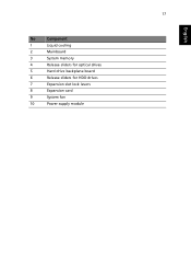
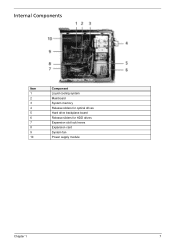
17 English No Component 1 Liquid cooling 2 Mainboard 3 System memory 4 Release sliders for optical drives 5 Hard drive backplane board 6 Release sliders for HDD drives 7 Expansion slot lock levers 8 Expansion card 9 System fan 10 Power supply module
17 English No Component 1 Liquid cooling 2 Mainboard 3 System memory 4 Release sliders for optical drives 5 Hard drive backplane board 6 Release sliders for HDD drives 7 Expansion slot lock levers 8 Expansion card 9 System fan 10 Power supply module
Aspire G7700 Series User's Guide
Page 34
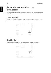
Reset button Press this reset button (RESET1) on or off or reset the computer when user testing the system. Power button Press the power button (POWER1) on the mainboard to reset the system. English 22 2 System tour System board switches and connectors The System board switches are easy to turn the system on the mainboard to turn off .
Reset button Press this reset button (RESET1) on or off or reset the computer when user testing the system. Power button Press the power button (POWER1) on the mainboard to reset the system. English 22 2 System tour System board switches and connectors The System board switches are easy to turn the system on the mainboard to turn off .
Aspire G7700 Series User's Guide
Page 39
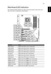
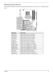
... functional. Lights when PCI E2 slot is functional. Lights when PCI1 slot is functional. Lights when PCI E4 slot is functional. English 27 Mainboard LED indicators The mainboard LED indicators are easy to check the system status when user open the cover or testing the system board... Lights when PCI E3 slot...
... functional. Lights when PCI E2 slot is functional. Lights when PCI1 slot is functional. Lights when PCI E4 slot is functional. English 27 Mainboard LED indicators The mainboard LED indicators are easy to check the system status when user open the cover or testing the system board... Lights when PCI E3 slot...

Aspire G7700 Series User's Guide
Page 107
The DDR2 DIMMs require 1.8 volts. Each channel is made up of 8 GB. The mainboard has four DDR2 DIMM slots divided into two channels. You can install PC2 6400/DDR2 800, or PC2 8500/DDR2 1066 modules in the DDR2 ... slots. DIMM 1 and DIMM 2 • Channel B - Contact your dealer for removing and installing a memory module. System memory interface The four 240-pin sockets on the mainboard support Double Data Rate 2 (DDR2) Synchronous Dynamic Random Access Memory (SDRAM)-type DIMMs. You may install 512 MB, 1 GB or 2 GB DIMMs for a maximum memory...
The DDR2 DIMMs require 1.8 volts. Each channel is made up of 8 GB. The mainboard has four DDR2 DIMM slots divided into two channels. You can install PC2 6400/DDR2 800, or PC2 8500/DDR2 1066 modules in the DDR2 ... slots. DIMM 1 and DIMM 2 • Channel B - Contact your dealer for removing and installing a memory module. System memory interface The four 240-pin sockets on the mainboard support Double Data Rate 2 (DDR2) Synchronous Dynamic Random Access Memory (SDRAM)-type DIMMs. You may install 512 MB, 1 GB or 2 GB DIMMs for a maximum memory...
Aspire G7700 Series User's Guide
Page 109
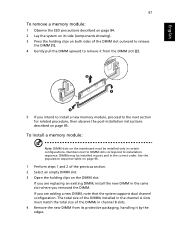
To install a memory module: Note: DIMM slots on the mainboard must match the total size of the DIMM slot outward to release the DIMM (1). 4 Gently pull the DIMM upward to remove it by the edges. ...
To install a memory module: Note: DIMM slots on the mainboard must match the total size of the DIMM slot outward to release the DIMM (1). 4 Gently pull the DIMM upward to remove it by the edges. ...

Aspire G7700 Series User's Guide
Page 113
... the second PCI Express power cord from the SLI-Ready power supply and plug it was before °V the "top" card, or original card that mainboard. The system comes with an SLI connector designed to connect the two graphic cards. Note: When you power up the PC, you'll want to...
... the second PCI Express power cord from the SLI-Ready power supply and plug it was before °V the "top" card, or original card that mainboard. The system comes with an SLI connector designed to connect the two graphic cards. Note: When you power up the PC, you'll want to...

Aspire G7700 Series User's Guide
Page 136
... mouse 32 connecting power cable 35 keyboard 31 monitor 31 mouse 31 side panel install 89 remove 89 system board audio card 21 connectors 22 mainboard 18 switches 22 system memory install 97 system tuning 79 T turning off computer 38 software shutdown 38 suspend mode 38 turning on computer 36 power... button 36 power switch 36 U upgrade computer 95 installation precautions post-installation 85 open computer 86 remove computer cover 86 replace components memory 95 AS G7700 V1.0
... mouse 32 connecting power cable 35 keyboard 31 monitor 31 mouse 31 side panel install 89 remove 89 system board audio card 21 connectors 22 mainboard 18 switches 22 system memory install 97 system tuning 79 T turning off computer 38 software shutdown 38 suspend mode 38 turning on computer 36 power... button 36 power switch 36 U upgrade computer 95 installation precautions post-installation 85 open computer 86 remove computer cover 86 replace components memory 95 AS G7700 V1.0
Aspire G7700 Service Guide
Page 7
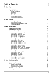
Table of Contents System Tour 1 Features 1 Aspire G7700 Tour 4 Closed Front Panel 4 Front Panel 5 Rear Panel 6 Internal Components 7 System LED Indicators 8 Mainboard LED indicators 9 System Utilities 11 CMOS Setup Utility 11 Entering CMOS setup 12 Navigating Through the Setup Utility 12...Removing the Power Supply 56 Removing the HDD Fan 58 Removing the Top Cover 59 Removing the USB Board 60 Removing the Mainboard 62 Removing the Front Foot Stand 64 Removing the Rear Foot Stand 65 System Troubleshooting 67 Hardware Diagnostic Procedure 67 System Check...
Table of Contents System Tour 1 Features 1 Aspire G7700 Tour 4 Closed Front Panel 4 Front Panel 5 Rear Panel 6 Internal Components 7 System LED Indicators 8 Mainboard LED indicators 9 System Utilities 11 CMOS Setup Utility 11 Entering CMOS setup 12 Navigating Through the Setup Utility 12...Removing the Power Supply 56 Removing the HDD Fan 58 Removing the Top Cover 59 Removing the USB Board 60 Removing the Mainboard 62 Removing the Front Foot Stand 64 Removing the Rear Foot Stand 65 System Troubleshooting 67 Hardware Diagnostic Procedure 67 System Check...
Aspire G7700 Service Guide
Page 15
Internal Components Item 1 2 3 4 5 6 7 8 9 10 Component Liquid cooling system Mainboard System memory Release sliders for optical drives Hard drive backplane board Release sliders for HDD drives Expansion slot lock levers Expansion card System fan Power supply module Chapter 1 7
Internal Components Item 1 2 3 4 5 6 7 8 9 10 Component Liquid cooling system Mainboard System memory Release sliders for optical drives Hard drive backplane board Release sliders for HDD drives Expansion slot lock levers Expansion card System fan Power supply module Chapter 1 7
Aspire G7700 Service Guide
Page 17
Lights when PCI E4 slot is functional. Lights when the DIMM1 slot is functional. Mainboard LED indicators The mainboard LED indicators are easy to check the system status when user open the cover or testing the system board. Lights when the system is functional. ...
Lights when PCI E4 slot is functional. Lights when the DIMM1 slot is functional. Mainboard LED indicators The mainboard LED indicators are easy to check the system status when user open the cover or testing the system board. Lights when the system is functional. ...

Aspire G7700 Service Guide
Page 30
.... Auto Set the memory reference voltage. Auto Set the memory terminator voltage. Set the NB GTL reference voltage to provide the best level of the mainboard's EMI. Note: Remember to override the memory's Serial Presence Detect (SPD) settings by manually entering values for DRAM timings. Enabled Disabled Select processor voltage control...
.... Auto Set the memory reference voltage. Auto Set the memory terminator voltage. Set the NB GTL reference voltage to provide the best level of the mainboard's EMI. Note: Remember to override the memory's Serial Presence Detect (SPD) settings by manually entering values for DRAM timings. Enabled Disabled Select processor voltage control...

Aspire G7700 Service Guide
Page 39
... CARD READER DRIVE HDD CAGE MEMORY MODULES Ex4 LIQUID COOLER FAN ASSEMBLY CPU Gx4 POWER SUPPLY Hx4 HDD FAN TOP COVER Ix2 USB BOARD Jx6 MAINBOARD FRONT AND REAR FOOT STANDS Ax4 HDD MODULE Dx2 BACKPLANE BOARD HDD 31
... CARD READER DRIVE HDD CAGE MEMORY MODULES Ex4 LIQUID COOLER FAN ASSEMBLY CPU Gx4 POWER SUPPLY Hx4 HDD FAN TOP COVER Ix2 USB BOARD Jx6 MAINBOARD FRONT AND REAR FOOT STANDS Ax4 HDD MODULE Dx2 BACKPLANE BOARD HDD 31
Aspire G7700 Service Guide
Page 46
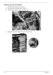
Disconnect the front panel cable from the chassis interior. 38 Chapter 3 Release the front bezel retention tabs from the mainboard. 4. See "Removing the Left Side Panel" on page 33. 2. See "Removing the Bezel Door" on page 36. 3. Removing the Front Bezel 1.
Disconnect the front panel cable from the chassis interior. 38 Chapter 3 Release the front bezel retention tabs from the mainboard. 4. See "Removing the Left Side Panel" on page 33. 2. See "Removing the Bezel Door" on page 36. 3. Removing the Front Bezel 1.
Aspire G7700 Service Guide
Page 49
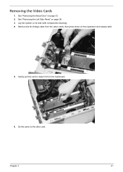
Gently pull the card to the other card. Do the same to detach it from the video cards, then press down on page 36. 3. See "Removing the Left Side Panel" on the expansion slot release latch. 5. Remove the SLI bridge cable from the mainboard. 6. Chapter 3 41 See "Removing the Bezel Door" on its side (with components showing). 4. Lay the system on page 33. 2. Removing the Video Cards 1.
Gently pull the card to the other card. Do the same to detach it from the video cards, then press down on page 36. 3. See "Removing the Left Side Panel" on the expansion slot release latch. 5. Remove the SLI bridge cable from the mainboard. 6. Chapter 3 41 See "Removing the Bezel Door" on its side (with components showing). 4. Lay the system on page 33. 2. Removing the Video Cards 1.
Aspire G7700 Service Guide
Page 51
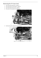
See "Removing the Bezel Door" on the expansion slot release latch. 5. Gently pull the card to detach it from the mainboard. Press down on page 33. 2. Removing the TV Tuner Card 1. Chapter 3 43 See "Removing the Video Cards" on page 36. 3. See "Removing the Left Side Panel" on page 41. 4.
See "Removing the Bezel Door" on the expansion slot release latch. 5. Gently pull the card to detach it from the mainboard. Press down on page 33. 2. Removing the TV Tuner Card 1. Chapter 3 43 See "Removing the Video Cards" on page 36. 3. See "Removing the Left Side Panel" on page 41. 4.
Aspire G7700 Service Guide
Page 52
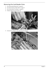
See "Removing the Bezel Door" on page 38. 4. See "Removing the Front Bezel" on page 33. 2. Release cables from the mainboard. 44 Chapter 3 Disconnect the USB and 1394 cables from the retention clip. 5. See "Removing the Left Side Panel" on page 36. 3. Removing the Card Reader Drive 1.
See "Removing the Bezel Door" on page 38. 4. See "Removing the Front Bezel" on page 33. 2. Release cables from the mainboard. 44 Chapter 3 Disconnect the USB and 1394 cables from the retention clip. 5. See "Removing the Left Side Panel" on page 36. 3. Removing the Card Reader Drive 1.
Aspire G7700 Service Guide
Page 58
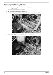
See "Removing the Bezel Door" on page 36. 3. Press the holding clips on both sides of the DIMM slot outward to pull it away from the memory board, make sure to create a backup file of all important data. 1. See "Removing the Left Side Panel" on page 33. 2. Gently pull the DIMM upward and to release the DIMM. 4. Removing the Memory Modules IMPORTANT:Before removing any DIMM from the mainboard. 50 Chapter 3
See "Removing the Bezel Door" on page 36. 3. Press the holding clips on both sides of the DIMM slot outward to pull it away from the memory board, make sure to create a backup file of all important data. 1. See "Removing the Left Side Panel" on page 33. 2. Gently pull the DIMM upward and to release the DIMM. 4. Removing the Memory Modules IMPORTANT:Before removing any DIMM from the mainboard. 50 Chapter 3

Aspire G7700 Service Guide
Page 60
Lift the fan and heat exchanger end of the liquid cooler fan assembly to the chassis. Lay cooler on its side-with the thermal patch facing sideways. Do not let the thermal patch touch the work surface. 9. 6. Remove the four screws (E) securing the fan end of the liquid cooler assembly from the chassis, then gently detach the cooler end from both the liquid cooler and the processor. 52 Chapter 3 Screw (Quantity) Liquid cooler screw (4) Color Black Torque 4.5 to wipe off the thermal grease from the mainboard. 8. Use an alcohol pad to 5.5 kgf-cm Part No. N/A 7.
Lift the fan and heat exchanger end of the liquid cooler fan assembly to the chassis. Lay cooler on its side-with the thermal patch facing sideways. Do not let the thermal patch touch the work surface. 9. 6. Remove the four screws (E) securing the fan end of the liquid cooler assembly from the chassis, then gently detach the cooler end from both the liquid cooler and the processor. 52 Chapter 3 Screw (Quantity) Liquid cooler screw (4) Color Black Torque 4.5 to wipe off the thermal grease from the mainboard. 8. Use an alcohol pad to 5.5 kgf-cm Part No. N/A 7.
Aspire G7700 Service Guide
Page 62
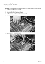
See "Removing the Left Side Panel" on . WARNING:The processor becomes very hot when the system is on page 36. 3. See "Removing the Bezel Door" on page 51. 5. Lift the load lever up and open the load plate. 54 Chapter 3 Allow it to release load lever. 6. See "Removing the Liquid Cooler Fan Assembly" on page 33. 2. Press down to cool off first before handling. 1. See "Removing the Memory Modules" on page 50. 4. Removing the Processor IMPORTANT:Before removing a processor from the mainboard, make sure to create a backup file of all important data.
See "Removing the Left Side Panel" on . WARNING:The processor becomes very hot when the system is on page 36. 3. See "Removing the Bezel Door" on page 51. 5. Lift the load lever up and open the load plate. 54 Chapter 3 Allow it to release load lever. 6. See "Removing the Liquid Cooler Fan Assembly" on page 33. 2. Press down to cool off first before handling. 1. See "Removing the Memory Modules" on page 50. 4. Removing the Processor IMPORTANT:Before removing a processor from the mainboard, make sure to create a backup file of all important data.

