Acer Aspire 7750, 7750G, 7750Z Notebook Service Guide
Page 6
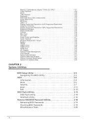
... Hard Disk Drive (AVL components 1-30 Super-Multi Drive 1-32 BD Drive 1-33 LED 17.3 1-34 Display Supported Resolution (LCD Supported Resolution 1-34 Graphics Controller 1-35 Display Supported Resolution (GPU Supported Resolution 1-35 Bluetooth Interface 1-35 Bluetooth Module 1-36 Camera 1-36 Mini Card 1-36 3G Card 1-36 Audio Codec and Amplifier 1-37 Audio Interface 1-38 Wireless Module 802.11b/g/n 1-38 Battery 1-39 VRAM 1-39 USB2.0 Port 1-39 USB3.0 Port 1-40 HDMI Port 1-40 AC Adapter 1-40 System Power Management 1-40 Card Reader 1-41 System LED Indicator...
... Hard Disk Drive (AVL components 1-30 Super-Multi Drive 1-32 BD Drive 1-33 LED 17.3 1-34 Display Supported Resolution (LCD Supported Resolution 1-34 Graphics Controller 1-35 Display Supported Resolution (GPU Supported Resolution 1-35 Bluetooth Interface 1-35 Bluetooth Module 1-36 Camera 1-36 Mini Card 1-36 3G Card 1-36 Audio Codec and Amplifier 1-37 Audio Interface 1-38 Wireless Module 802.11b/g/n 1-38 Battery 1-39 VRAM 1-39 USB2.0 Port 1-39 USB3.0 Port 1-40 HDMI Port 1-40 AC Adapter 1-40 System Power Management 1-40 Card Reader 1-41 System LED Indicator...

Acer Aspire 7750, 7750G, 7750Z Notebook Service Guide
Page 7
... Module Removal 3-12 HDD Module Installation 3-13 DIMM Module Removal 3-14 DIMM Module Installation 3-14 WLAN Module Removal 3-15 WLAN Module Installation 3-15 RTC Battery Removal 3-16 RTC Battery Installation 3-16 ODD Module Removal 3-17 ODD Module Installation 3-18 Keyboard Removal 3-19 Keyboard Installation 3-20 Upper Cover Removal 3-21 Upper Cover Installation 3-22 Power Board Removal 3-23 Power Board Installation 3-23 Bluetooth Module Removal 3-24 Bluetooth Module Installation 3-24 USB Module Removal 3-25 USB Module Installation 3-25 LAN Module Removal 3-26 LAN Module...
... Module Removal 3-12 HDD Module Installation 3-13 DIMM Module Removal 3-14 DIMM Module Installation 3-14 WLAN Module Removal 3-15 WLAN Module Installation 3-15 RTC Battery Removal 3-16 RTC Battery Installation 3-16 ODD Module Removal 3-17 ODD Module Installation 3-18 Keyboard Removal 3-19 Keyboard Installation 3-20 Upper Cover Removal 3-21 Upper Cover Installation 3-22 Power Board Removal 3-23 Power Board Installation 3-23 Bluetooth Module Removal 3-24 Bluetooth Module Installation 3-24 USB Module Removal 3-25 USB Module Installation 3-25 LAN Module Removal 3-26 LAN Module...

Acer Aspire 7750, 7750G, 7750Z Notebook Service Guide
Page 23
... Off. Hard Disk Drive Indicates when the hard disk drive is charging. 2. Closed Front View 0 1 2 Figure 1-2. Fully charged: The light shows blue when in -1 card Accepts Secure Digital (SD), MultiMediaCard reader (MMC), Memory Stick PRO (MS PRO), xD-Picture Card (xD). Hardware Specifications and Configurations 1-13 Closed Front View Table 1-2. Battery indicator Indicates the computer's battery status. 1. Charging: The light shows amber when the battery is active. (HDD) indicator Communication key Enables/disables the computer's communication devices. (Communication...
... Off. Hard Disk Drive Indicates when the hard disk drive is charging. 2. Closed Front View 0 1 2 Figure 1-2. Fully charged: The light shows blue when in -1 card Accepts Secure Digital (SD), MultiMediaCard reader (MMC), Memory Stick PRO (MS PRO), xD-Picture Card (xD). Hardware Specifications and Configurations 1-13 Closed Front View Table 1-2. Battery indicator Indicates the computer's battery status. 1. Charging: The light shows amber when the battery is active. (HDD) indicator Communication key Enables/disables the computer's communication devices. (Communication...
Acer Aspire 7750, 7750G, 7750Z Notebook Service Guide
Page 24
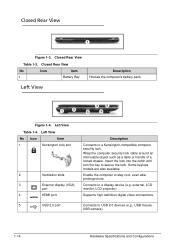
... or handle of a locked drawer. Connects to USB 2.0 devices (e.g., USB mouse, USB camera). 1-14 Hardware Specifications and Configurations Supports high definition digital video connections. 5 USB 2.0 port Connects to a display device (e.g. Closed Rear View 0 1 Figure 1-3. Left View No Icon Item 1 Kensington lock slot 2 Ventilation slots 3 External display (VGA) port 4 HDMI port Description Connects to stay cool, even after prolonged use. Enable the computer to a Kensington-compatible computer security lock. external, LCD monitor, LCD projector). Closed Rear View...
... or handle of a locked drawer. Connects to USB 2.0 devices (e.g., USB mouse, USB camera). 1-14 Hardware Specifications and Configurations Supports high definition digital video connections. 5 USB 2.0 port Connects to a display device (e.g. Closed Rear View 0 1 Figure 1-3. Left View No Icon Item 1 Kensington lock slot 2 Ventilation slots 3 External display (VGA) port 4 HDMI port Description Connects to stay cool, even after prolonged use. Enable the computer to a Kensington-compatible computer security lock. external, LCD monitor, LCD projector). Closed Rear View...

Acer Aspire 7750, 7750G, 7750Z Notebook Service Guide
Page 25
...-based network. 8 DC-in jack Description Accepts inputs from the drive. Hardware Specifications and Configurations 1-15 Lights up when the optical drive is active. Headphone/speaker jack Connects to USB devices. * A USB 3.0 port can be compatible. Right View No Icon Item 1 USB 2.0 port 2 USB 2.0 / 3.0* port 3 Optical drive 4 Optical disk access indicator 5 Optical drive eject button 6 Emergency eject hole 7 Ethernet (RJ-45) port Description Connects to an AC adapter. Ejects the optical disk from external microphones. Right View Table 1-5. Devices without USB...
...-based network. 8 DC-in jack Description Accepts inputs from the drive. Hardware Specifications and Configurations 1-15 Lights up when the optical drive is active. Headphone/speaker jack Connects to USB devices. * A USB 3.0 port can be compatible. Right View No Icon Item 1 USB 2.0 port 2 USB 2.0 / 3.0* port 3 Optical drive 4 Optical disk access indicator 5 Optical drive eject button 6 Emergency eject hole 7 Ethernet (RJ-45) port Description Connects to an AC adapter. Ejects the optical disk from external microphones. Right View Table 1-5. Devices without USB...

Acer Aspire 7750, 7750G, 7750Z Notebook Service Guide
Page 26
Base View Table 1-6. Releases the battery for certain models only). 1-16 Hardware Specifications and Configurations Base View No Icon Item 1 Battery bay 2 Battery release latch/lock Description Houses the computer's battery pack. Insert a suitable tool into the latch and slide to release. 3 Memory Houses the computer's main memory. compartment 4 Hard disk bay-Main Houses the computer's hard disk (secured with screws). 5 Hard disk Houses the computer's hard disk (secured with screws) bay-Secondary (for removal. Base View 0 1 2 3 4 5 Figure 1-6.
Base View Table 1-6. Releases the battery for certain models only). 1-16 Hardware Specifications and Configurations Base View No Icon Item 1 Battery bay 2 Battery release latch/lock Description Houses the computer's battery pack. Insert a suitable tool into the latch and slide to release. 3 Memory Houses the computer's main memory. compartment 4 Hard disk bay-Main Houses the computer's hard disk (secured with screws). 5 Hard disk Houses the computer's hard disk (secured with screws) bay-Secondary (for removal. Base View 0 1 2 3 4 5 Figure 1-6.
Acer Aspire 7750, 7750G, 7750Z Notebook Service Guide
Page 27
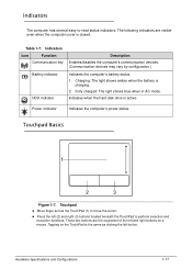
... left and right buttons on the TouchPad is closed. Charging: The light shows amber when the battery is active. Touchpad Basics 0 1 2 3 Figure 1-7. Touchpad Move finger across the TouchPad (1) to move the cursor. Press the left button. Table 1-7. Power indicator Indicates the computer's power status. Hardware Specifications and Configurations 1-17 Indicates when the hard disk drive is charging. 2. These two buttons are visible even when the computer cover is the same...
... left and right buttons on the TouchPad is closed. Charging: The light shows amber when the battery is active. Touchpad Basics 0 1 2 3 Figure 1-7. Touchpad Move finger across the TouchPad (1) to move the cursor. Press the left button. Table 1-7. Power indicator Indicates the computer's power status. Hardware Specifications and Configurations 1-17 Indicates when the hard disk drive is charging. 2. These two buttons are visible even when the computer cover is the same...

Acer Aspire 7750, 7750G, 7750Z Notebook Service Guide
Page 29
... of Access Center Application key This key has the same effect as clicking the right mouse button; It can also be used with other keys to items on the Quick Launch toolbar and the system tray) < > + : Cycle through programs on the Windows Start button; Functions supported by Windows XP: < > + : Show the System Properties dialog box < > + : Open Ease of functions. Hardware Specifications and Configurations 1-19 Windows Keys 0 The keyboard has two keys that perform Windows-specific functions...
... of Access Center Application key This key has the same effect as clicking the right mouse button; It can also be used with other keys to items on the Quick Launch toolbar and the system tray) < > + : Cycle through programs on the Windows Start button; Functions supported by Windows XP: < > + : Show the System Properties dialog box < > + : Open Ease of functions. Hardware Specifications and Configurations 1-19 Windows Keys 0 The keyboard has two keys that perform Windows-specific functions...

Acer Aspire 7750, 7750G, 7750Z Notebook Service Guide
Page 30
... used to access most of the computer's controls like screen brightness and volume output. Turns Off LCD back light Touchpad toggle Speaker toggle Turns touchpad On or Off. Plays or pauses media file. Keyboard Hotkeys Table 1-11. Sleep Puts computer in the combination. Brightness Down Play/Pause Decreases screen brightness. Volume up window. Stop Stops media file. 1-20 Hardware Specifications and Configurations To activate hotkeys, press and hold the key before pressing the key in Sleep mode. + + + + + Display toggle Display off Switches display output...
... used to access most of the computer's controls like screen brightness and volume output. Turns Off LCD back light Touchpad toggle Speaker toggle Turns touchpad On or Off. Plays or pauses media file. Keyboard Hotkeys Table 1-11. Sleep Puts computer in the combination. Brightness Down Play/Pause Decreases screen brightness. Volume up window. Stop Stops media file. 1-20 Hardware Specifications and Configurations To activate hotkeys, press and hold the key before pressing the key in Sleep mode. + + + + + Display toggle Display off Switches display output...
Acer Aspire 7750, 7750G, 7750Z Notebook Service Guide
Page 39
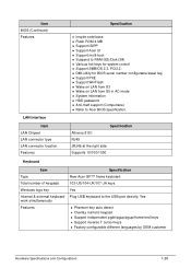
... pgdn/pgup/pgup/home/end keys Support reverse T cursor keys Factory configurable different languages by OEM customer Hardware Specifications and Configurations 1-29 Item LAN Chipset LAN connector type LAN connector location Features Specification Atheros 8151 RJ45 JRJ45 at the right side Supports 10/100/1000 Keyboard Item Type Total number of keypads Windows logo key Internal & external keyboard work simultaneously Features Specification New Acer GF7T frame keyboard 103-US/104-UK/107-JA keys Yes Plug USB keyboard to Acer BIOS specification.
... pgdn/pgup/pgup/home/end keys Support reverse T cursor keys Factory configurable different languages by OEM customer Hardware Specifications and Configurations 1-29 Item LAN Chipset LAN connector type LAN connector location Features Specification Atheros 8151 RJ45 JRJ45 at the right side Supports 10/100/1000 Keyboard Item Type Total number of keypads Windows logo key Internal & external keyboard work simultaneously Features Specification New Acer GF7T frame keyboard 103-US/104-UK/107-JA keys Yes Plug USB keyboard to Acer BIOS specification.

Acer Aspire 7750, 7750G, 7750Z Notebook Service Guide
Page 46
Bluetooth Module Item Controller Features Camera Item Vendor and Model Type Mini Card Item Number supported Features 3G Card Features Item Specification Atheros BU12 / Atheros AR3011/ Broadcom BCM2070/ Broadcom BCM2046 Bluetooth 3.0 compliant Point-to-multipoint operation External USB interface for data Onboard antenna and SMA RF connector Coexistence support Specification Chicony CNFA13021004970LH, Lite-on 10P2TF103, Suyin HF1316-P80A-SS03 1.3M...
Bluetooth Module Item Controller Features Camera Item Vendor and Model Type Mini Card Item Number supported Features 3G Card Features Item Specification Atheros BU12 / Atheros AR3011/ Broadcom BCM2070/ Broadcom BCM2046 Bluetooth 3.0 compliant Point-to-multipoint operation External USB interface for data Onboard antenna and SMA RF connector Coexistence support Specification Chicony CNFA13021004970LH, Lite-on 10P2TF103, Suyin HF1316-P80A-SS03 1.3M...

Acer Aspire 7750, 7750G, 7750Z Notebook Service Guide
Page 59
... a problem arises. The utility is a hardware configuration program built into a computer's BIOS (Basic Input/Output System). use the left and right arrow keys Item - Navigation keys appear at the bottom of screen. System Utilities BIOS Setup Utility 0 This utility is pre-configured and optimized so most users do not need to be changed if enclosed in the Item Specific Help area of the screen. To change the boot device without entering BIOS Setup Utility, set to Disabled...
... a problem arises. The utility is a hardware configuration program built into a computer's BIOS (Basic Input/Output System). use the left and right arrow keys Item - Navigation keys appear at the bottom of screen. System Utilities BIOS Setup Utility 0 This utility is pre-configured and optimized so most users do not need to be changed if enclosed in the Item Specific Help area of the screen. To change the boot device without entering BIOS Setup Utility, set to Disabled...

Acer Aspire 7750, 7750G, 7750Z Notebook Service Guide
Page 66
If the password entered does not match the current password, the screen shows the Setup Warning dialog. (Figure 2-8) Figure 2-9. Setup Warning 2-10 System Utilities Press F10 to activate the password feature. 5. NOTE: NOTE: Password on Boot must be set to Enabled to save changes and exit BIOS Setup Utility. Figure 2-8. Setup Notice The password setting is OK, the screen shows as follows. If the verification is complete after the user presses Enter.
If the password entered does not match the current password, the screen shows the Setup Warning dialog. (Figure 2-8) Figure 2-9. Setup Warning 2-10 System Utilities Press F10 to activate the password feature. 5. NOTE: NOTE: Password on Boot must be set to Enabled to save changes and exit BIOS Setup Utility. Figure 2-8. Setup Notice The password setting is OK, the screen shows as follows. If the verification is complete after the user presses Enter.

Acer Aspire 7750, 7750G, 7750Z Notebook Service Guide
Page 80
... Module Removal 3-12 HDD Module Installation 3-13 DIMM Module Removal 3-14 DIMM Module Installation 3-14 WLAN Module Removal 3-15 WLAN Module Installation 3-15 RTC Battery Removal 3-16 RTC Battery Installation 3-16 ODD Module Removal 3-17 ODD Module Installation 3-18 Keyboard Removal 3-19 Keyboard Installation 3-20 Upper Cover Removal 3-21 Upper Cover Installation 3-22 Power Board Removal 3-23 Power Board Installation 3-23 Bluetooth Module Removal 3-24 Bluetooth Module Installation 3-24 USB Module Removal 3-25 USB Module Installation 3-25 LAN Module Removal 3-26 LAN Module...
... Module Removal 3-12 HDD Module Installation 3-13 DIMM Module Removal 3-14 DIMM Module Installation 3-14 WLAN Module Removal 3-15 WLAN Module Installation 3-15 RTC Battery Removal 3-16 RTC Battery Installation 3-16 ODD Module Removal 3-17 ODD Module Installation 3-18 Keyboard Removal 3-19 Keyboard Installation 3-20 Upper Cover Removal 3-21 Upper Cover Installation 3-22 Power Board Removal 3-23 Power Board Installation 3-23 Bluetooth Module Removal 3-24 Bluetooth Module Installation 3-24 USB Module Removal 3-25 USB Module Installation 3-25 LAN Module Removal 3-26 LAN Module...

Acer Aspire 7750, 7750G, 7750Z Notebook Service Guide
Page 101
Install and secure two (2) screws (C) to upper cover. 3. Locate power board (A) on upper cover. 2. Guide FFC cable (D) through upper cover opening (E). 4. B C A C D E Figure 3-18. Put board (A) and module (B) onto upper cover. 2. ID Size C M2.5*3 Ni Quantity 2 0 Screw Type Machine Maintenance Procedures 3-23 Install upper cover. Power Board Removal 0 Prerequisite: Upper Cover Removal 1. Lift board (A) from upper cover. 5. Remove power saver module (B) from upper cover. Power Board Power Board Installation 1. Remove two (2) screws (C) securing board to board (A)....
Install and secure two (2) screws (C) to upper cover. 3. Locate power board (A) on upper cover. 2. Guide FFC cable (D) through upper cover opening (E). 4. B C A C D E Figure 3-18. Put board (A) and module (B) onto upper cover. 2. ID Size C M2.5*3 Ni Quantity 2 0 Screw Type Machine Maintenance Procedures 3-23 Install upper cover. Power Board Removal 0 Prerequisite: Upper Cover Removal 1. Lift board (A) from upper cover. 5. Remove power saver module (B) from upper cover. Power Board Power Board Installation 1. Remove two (2) screws (C) securing board to board (A)....

Acer Aspire 7750, 7750G, 7750Z Notebook Service Guide
Page 125
... intended for troubleshooting computer problems. The step by re-creating the failure through diagnostic tests or repeating the operation that led to the problem. 3. Troubleshooting Introduction 0 This chapter contains information about the problem. 2. Non-Acer products, prototype cards, or modified options can give false errors and invalid system responses. 1. Table 4-1. NOTE: NOTE: Do not replace a non-defective FRU. Use Table 4-1 with the notebook. Obtain as...
... intended for troubleshooting computer problems. The step by re-creating the failure through diagnostic tests or repeating the operation that led to the problem. 3. Troubleshooting Introduction 0 This chapter contains information about the problem. 2. Non-Acer products, prototype cards, or modified options can give false errors and invalid system responses. 1. Table 4-1. NOTE: NOTE: Do not replace a non-defective FRU. Use Table 4-1 with the notebook. Obtain as...

Acer Aspire 7750, 7750G, 7750Z Notebook Service Guide
Page 127
... RAM module Replace M/B CPU thermal module well No screw? Fasten Screw Figure 4-2. Reference Product pages for 10 seconds. 4. DDRRAM module well No connected? Make sure the computer has power by checking for one at a time. 1. START Replace LCD panel/ No LCD cable LCD module OK? Check connection Replace Ext. Switching between internal and external by removing the power cable and battery. Connect the power and reboot the computer. DDRRAM module OK? Hold the power button for specific model procedures. 2. Troubleshooting 4-5 Make sure that internal display...
... RAM module Replace M/B CPU thermal module well No screw? Fasten Screw Figure 4-2. Reference Product pages for 10 seconds. 4. DDRRAM module well No connected? Make sure the computer has power by checking for one at a time. 1. START Replace LCD panel/ No LCD cable LCD module OK? Check connection Replace Ext. Switching between internal and external by removing the power cable and battery. Connect the power and reboot the computer. DDRRAM module OK? Hold the power button for specific model procedures. 2. Troubleshooting 4-5 Make sure that internal display...
Acer Aspire 7750, 7750G, 7750Z Notebook Service Guide
Page 128
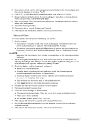
...;If extensive pixel damage is present (different colored spots in the same locations on -screen prompts. 9. Refer to Online Support Information. 8. Remove any memory cards and CD/DVD discs. 8. Start the computer. If the display is properly installed. Roll back the video driver to Online Support Information. 4-6 Troubleshooting Check the Device Manager to determine that the computer is still not resolved, refer to the previous version...
...;If extensive pixel damage is present (different colored spots in the same locations on -screen prompts. 9. Refer to Online Support Information. 8. Remove any memory cards and CD/DVD discs. 8. Start the computer. If the display is properly installed. Roll back the video driver to Online Support Information. 4-6 Troubleshooting Check the Device Manager to determine that the computer is still not resolved, refer to the previous version...

Acer Aspire 7750, 7750G, 7750Z Notebook Service Guide
Page 140
... if external modules are functioning correctly. Change mainboard to check if current one at a time until failing FRU is found , replace the FRU. 3. When analyzing an intermittent problem, perform the following devices: Non-Acer devices Printer, mouse, and other external devices Battery pack Hard disk drive DIMM CD-ROM/Diskette drive Module PC Cards 4. Remove power...
... if external modules are functioning correctly. Change mainboard to check if current one at a time until failing FRU is found , replace the FRU. 3. When analyzing an intermittent problem, perform the following devices: Non-Acer devices Printer, mouse, and other external devices Battery pack Hard disk drive DIMM CD-ROM/Diskette drive Module PC Cards 4. Remove power...

Acer Aspire 7750, 7750G, 7750Z Notebook Service Guide
Page 144
... BDS_BEFORE_PCIIO_INSTALL BDS_PCI_ENUMERATION_END BDS_CONNECT_CONSOLE_IN Phase Post Code Description BDS 10 Enter BDS entry BDS 11 Install Hotkey service BDS 12 ASF Initialization BDS 13 PCI enumeration BDS 14 PCI resource assign complete BDS 15 PCI enumeration complete BDS 16 Keyboard Controller, keyboard and mouse initialization 4-22 Troubleshooting DXE Phase POST Code Table (Continued) Functionality Name (Include\PostCode.h) Phase Post Code Description DXE_SMART_TIMER_INIT DXE 51...
... BDS_BEFORE_PCIIO_INSTALL BDS_PCI_ENUMERATION_END BDS_CONNECT_CONSOLE_IN Phase Post Code Description BDS 10 Enter BDS entry BDS 11 Install Hotkey service BDS 12 ASF Initialization BDS 13 PCI enumeration BDS 14 PCI resource assign complete BDS 15 PCI enumeration complete BDS 16 Keyboard Controller, keyboard and mouse initialization 4-22 Troubleshooting DXE Phase POST Code Table (Continued) Functionality Name (Include\PostCode.h) Phase Post Code Description DXE_SMART_TIMER_INIT DXE 51...


