Acer Aspire 7535 Notebook Service Guide
Page 8
...the CPU 82 LCD Module Disassembly Process 84 LCD Module Disassembly Flowchart 84 Removing the LCD Bezel 85 Removing the LCD panel with the Brackets 88 Removing the LCD Brackets 90 Removing the Web Camera 90 Removing the Microphone Module 91 Removing the FPC Cable 93 Removing ...FRU (Field Replaceable Unit) List 121 Aspire 7738/7738G Series, Aspire7735/7735G/7735Z/7735ZG Series and Aspire 7535/7535G/7235 Series Exploded Diagram 122 Model Definition and Configuration 183 Aspire 7738/7738G Series 184 Aspire 7735/7735G/7735Z/7735ZG Series 193 Aspire 7535/7535G/7235 Series 198 Test ...
...the CPU 82 LCD Module Disassembly Process 84 LCD Module Disassembly Flowchart 84 Removing the LCD Bezel 85 Removing the LCD panel with the Brackets 88 Removing the LCD Brackets 90 Removing the Web Camera 90 Removing the Microphone Module 91 Removing the FPC Cable 93 Removing ...FRU (Field Replaceable Unit) List 121 Aspire 7738/7738G Series, Aspire7735/7735G/7735Z/7735ZG Series and Aspire 7535/7535G/7235 Series Exploded Diagram 122 Model Definition and Configuration 183 Aspire 7738/7738G Series 184 Aspire 7735/7735G/7735Z/7735ZG Series 193 Aspire 7535/7535G/7235 Series 198 Test ...
Acer Aspire 7535 Notebook Service Guide
Page 50
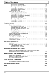
...system on a flat, stable surface. 4. Observe the order of the sequence to avoid damage to the system and all power and signal cables from the system. 3. General Information Pre-disassembly Instructions Before proceeding with the disassembly procedure, make sure that order. Remove the battery pack... Process The disassembly process is divided into the following stages: • External module disassembly • Main unit disassembly • LCD module disassembly The flowcharts provided in that you do the following: 1. Turn off the power to any of the hardware components.
...system on a flat, stable surface. 4. Observe the order of the sequence to avoid damage to the system and all power and signal cables from the system. 3. General Information Pre-disassembly Instructions Before proceeding with the disassembly procedure, make sure that order. Remove the battery pack... Process The disassembly process is divided into the following stages: • External module disassembly • Main unit disassembly • LCD module disassembly The flowcharts provided in that you do the following: 1. Turn off the power to any of the hardware components.
Acer Aspire 7535 Notebook Service Guide
Page 69
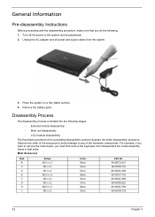
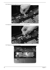
...Removing the Middle Cover" on page 48. 5. Chapter 3 61 Release the keyboard from its connector on the main board and detach the keyboard. Removing the LCD Module 1. See "Removing the Back Cover" on page 57. 11. See "Removing the DIMM Module" on page 54. 10. See "Removing the Optical Drive ...Module" on page 53. 9. Release the latch (a) and disconnect the keyboard cable (b) from the latches and turn it over on page 60. See "Removing the Battery Pack" on page 48. 6. See "Removing the Hard Disk Drive 1 (...
...Removing the Middle Cover" on page 48. 5. Chapter 3 61 Release the keyboard from its connector on the main board and detach the keyboard. Removing the LCD Module 1. See "Removing the Back Cover" on page 57. 11. See "Removing the DIMM Module" on page 54. 10. See "Removing the Optical Drive ...Module" on page 53. 9. Release the latch (a) and disconnect the keyboard cable (b) from the latches and turn it over on page 60. See "Removing the Battery Pack" on page 48. 6. See "Removing the Hard Disk Drive 1 (...
Acer Aspire 7535 Notebook Service Guide
Page 70
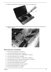
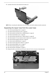
Remove the LCD cable from the latches. 62 Chapter 3 Release the cables from its connector on the main board. 14. Remove the DC-IN cable from its connector on the main board. 13. 12.
Remove the LCD cable from the latches. 62 Chapter 3 Release the cables from its connector on the main board. 14. Remove the DC-IN cable from its connector on the main board. 13. 12.
Acer Aspire 7535 Notebook Service Guide
Page 72
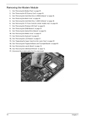
... Drive 2 (HDD2) Module" on page 50. 7. See "Removing the TV Tuner Card (for certain models only)" on page 46. 4. Carefully remove the LCD module from the Lower Case 1. See "Removing the Hard Disk Drive 1 (HDD1) Module" on the main board. 64 Chapter 3 Release the latch (a) and... disconnect the launch cable (b) from its connector on page 48. 6. See "Removing the Wireless LAN Card" on page 48. 5. See "Removing the Back Cover" on page 52. ...
... Drive 2 (HDD2) Module" on page 50. 7. See "Removing the TV Tuner Card (for certain models only)" on page 46. 4. Carefully remove the LCD module from the Lower Case 1. See "Removing the Hard Disk Drive 1 (HDD1) Module" on the main board. 64 Chapter 3 Release the latch (a) and... disconnect the launch cable (b) from its connector on page 48. 6. See "Removing the Wireless LAN Card" on page 48. 5. See "Removing the Back Cover" on page 52. ...
Acer Aspire 7535 Notebook Service Guide
Page 82
... 45. 3. See "Separating the Upper Case from the main board. 74 Chapter 3 Disconnect the modem cable from the Lower Case" on page 48. 6. See "Removing the SD Dummy Card" on page 50. 7. See "Removing the LCD Module" on page 54. 10. See "Removing the Optical Drive Module" on page 61. 13. See...
... 45. 3. See "Separating the Upper Case from the main board. 74 Chapter 3 Disconnect the modem cable from the Lower Case" on page 48. 6. See "Removing the SD Dummy Card" on page 50. 7. See "Removing the LCD Module" on page 54. 10. See "Removing the Optical Drive Module" on page 61. 13. See...
Acer Aspire 7535 Notebook Service Guide
Page 97
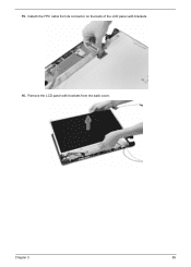
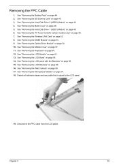
Remove the LCD panel with brackets. 16. Detach the FPC cable from its connector on the back of the LCD panel with brackets from the back cover. Chapter 3 89 15.
Remove the LCD panel with brackets. 16. Detach the FPC cable from its connector on the back of the LCD panel with brackets from the back cover. Chapter 3 89 15.

Acer Aspire 7535 Notebook Service Guide
Page 99
... 88. 15. See "Removing the SD Dummy Card" on page 48. 5. See "Removing the Back Cover" on page 45. 3. Disconnect the web camera cable from the LCD module back cover. See "Removing the LCD panel with the Brackets" on the web camera module. 17. WARNING: The web camera module is glued to the...) Module" on page 44. 2. Removing the Microphone Module 1. See "Removing the Hard Disk Drive 2 (HDD2) Module" on page 90. 16. Chapter 3 91 See "Removing the LCD Brackets" on page 46. 4. See "Removing the TV Tuner Card (for certain models only)" on page 85. 14. See "Removing the...
... 88. 15. See "Removing the SD Dummy Card" on page 48. 5. See "Removing the Back Cover" on page 45. 3. Disconnect the web camera cable from the LCD module back cover. See "Removing the LCD panel with the Brackets" on the web camera module. 17. WARNING: The web camera module is glued to the...) Module" on page 44. 2. Removing the Microphone Module 1. See "Removing the Hard Disk Drive 2 (HDD2) Module" on page 90. 16. Chapter 3 91 See "Removing the LCD Brackets" on page 46. 4. See "Removing the TV Tuner Card (for certain models only)" on page 85. 14. See "Removing the...

Acer Aspire 7535 Notebook Service Guide
Page 100
... "Removing the Keyboard" on page 90. 16. See "Removing the LCD Brackets" on page 60. 12. Detach adhesive tapes that glue the microphone cable to the back cover. See "Removing the LCD Bezel" on page 88. 15. See "Removing the LCD panel with the Brackets" on page 85. 14. See "Removing the... Web Camera" on page 61. 13. Detach the microphone cable from the LCD module back cover. 92 Chapter 3 See "Removing the LCD Module" on page 90. 17. 7. See "Removing the Wireless LAN Card" on page 53. 9. See "Removing the DIMM Module...
... "Removing the Keyboard" on page 90. 16. See "Removing the LCD Brackets" on page 60. 12. Detach adhesive tapes that glue the microphone cable to the back cover. See "Removing the LCD Bezel" on page 88. 15. See "Removing the LCD panel with the Brackets" on page 85. 14. See "Removing the... Web Camera" on page 61. 13. Detach the microphone cable from the LCD module back cover. 92 Chapter 3 See "Removing the LCD Module" on page 90. 17. 7. See "Removing the Wireless LAN Card" on page 53. 9. See "Removing the DIMM Module...
Acer Aspire 7535 Notebook Service Guide
Page 101
See "Removing the Optical Drive Module" on page 90. 16. See "Removing the LCD Brackets" on page 54. 10. Disconnect the FPC cable from the LCD panel. See "Removing the DIMM Module" on page 61. 13. See "Removing the LCD Module" on page 53. 9. See "Removing the Web Camera" on page 45. 3. Chapter 3... (for certain models only)" on page 48. 6. Detach all adhesive tapes and any cable that is glued to the LCD panel. 19. See "Removing the Hard Disk Drive 1 (HDD1) Module" on page 50. 7. See "Removing the LCD panel with the Brackets" on page 60. 12. See "Removing the Keyboard" on ...
See "Removing the Optical Drive Module" on page 90. 16. See "Removing the LCD Brackets" on page 54. 10. Disconnect the FPC cable from the LCD panel. See "Removing the DIMM Module" on page 61. 13. See "Removing the LCD Module" on page 53. 9. See "Removing the Web Camera" on page 45. 3. Chapter 3... (for certain models only)" on page 48. 6. Detach all adhesive tapes and any cable that is glued to the LCD panel. 19. See "Removing the Hard Disk Drive 1 (HDD1) Module" on page 50. 7. See "Removing the LCD panel with the Brackets" on page 60. 12. See "Removing the Keyboard" on ...
Acer Aspire 7535 Notebook Service Guide
Page 102
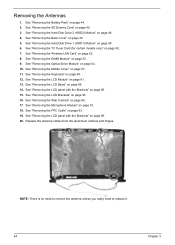
...on page 57. 11. See "Removing the Middle Cover" on page 53. 9. See "Removing the LCD panel with the Brackets" on page 88. 20. See "Removing the Web Camera" on page 48. 5. Release the antenna cables from the aluminium notches and hinges. See "Removing the Back Cover" on page 90. 17. See... Drive 1 (HDD1) Module" on page 85. 14. See "Removing the LCD Bezel" on page 48. 6. See "Removing the LCD panel with the Brackets" on page 60. 12. See "Removing the LCD Module" on page 93. 19. See "Removing the FPC Cable" on page 61. 13. See "Removing the Optical Drive Module" on page...
...on page 57. 11. See "Removing the Middle Cover" on page 53. 9. See "Removing the LCD panel with the Brackets" on page 88. 20. See "Removing the Web Camera" on page 48. 5. Release the antenna cables from the aluminium notches and hinges. See "Removing the Back Cover" on page 90. 17. See... Drive 1 (HDD1) Module" on page 85. 14. See "Removing the LCD Bezel" on page 48. 6. See "Removing the LCD panel with the Brackets" on page 60. 12. See "Removing the LCD Module" on page 93. 19. See "Removing the FPC Cable" on page 61. 13. See "Removing the Optical Drive Module" on page...
Acer Aspire 7535 Notebook Service Guide
Page 109
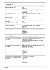
.... FRU/Action in BIOS Setup Utility. See "Power System Check" on page 97.. Ensure every connector is blank. LCD inverter ID LCD cable LCD inverter LCD System board Chapter 4 101 Error Message List Error Messages Fail-Safe Timer NMI Failed Device Address Conflict Allocation Error for ... in BIOS Setup Utility. Reconnect the DIMM. Reconnect the LCD connector Hard disk drive LCD inverter ID LCD cable LCD Inverter LCD System board Reconnect the LCD connectors. RTC battery System board Enter Setup and see POST on and LCD is connected tightly and correctly. No beep, power-on ...
.... FRU/Action in BIOS Setup Utility. See "Power System Check" on page 97.. Ensure every connector is blank. LCD inverter ID LCD cable LCD inverter LCD System board Chapter 4 101 Error Message List Error Messages Fail-Safe Timer NMI Failed Device Address Conflict Allocation Error for ... in BIOS Setup Utility. Reconnect the DIMM. Reconnect the LCD connector Hard disk drive LCD inverter ID LCD cable LCD Inverter LCD System board Reconnect the LCD connectors. RTC battery System board Enter Setup and see POST on and LCD is connected tightly and correctly. No beep, power-on ...
Acer Aspire 7535 Notebook Service Guide
Page 115
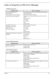
... Chapter 4 107 Action in Sequence Power source (battery pack and power adapter). See "Power System Check" on . LCD inverter ID LCD cable LCD inverter LCD System board Reconnect the LCD connector LCD inverter ID LCD cable LCD inverter LCD System board LCD inverter ID LCD inverter LCD cable LCD System board Indicator-Related Symptoms Symptom / Error Indicator incorrectly remains off or on, but system runs correctly...
... Chapter 4 107 Action in Sequence Power source (battery pack and power adapter). See "Power System Check" on . LCD inverter ID LCD cable LCD inverter LCD System board Reconnect the LCD connector LCD inverter ID LCD cable LCD inverter LCD System board LCD inverter ID LCD inverter LCD cable LCD System board Indicator-Related Symptoms Symptom / Error Indicator incorrectly remains off or on, but system runs correctly...

Acer Aspire 7535 Notebook Service Guide
Page 117
... Setup Utility to execute "Load Default Settings", then reboot system. LCD cover switch System board Remove battery pack and let it cool for 2 hours. Printer driver Printer cable Printer System Board Device driver Device cable Device System board Keyboard/Touchpad-Related Symptoms Symptom / Error Keyboard (...power off, then charge battery). Power Management-Related Symptoms Symptom / Error The system doesn't resume from standby mode after opening the LCD. Battery pack System board Reconnect hard disk/CD-ROM drives. USB does not work . Reconnect hard disk/CD-ROM/diskette drives. ...
... Setup Utility to execute "Load Default Settings", then reboot system. LCD cover switch System board Remove battery pack and let it cool for 2 hours. Printer driver Printer cable Printer System Board Device driver Device cable Device System board Keyboard/Touchpad-Related Symptoms Symptom / Error Keyboard (...power off, then charge battery). Power Management-Related Symptoms Symptom / Error The system doesn't resume from standby mode after opening the LCD. Battery pack System board Reconnect hard disk/CD-ROM drives. USB does not work . Reconnect hard disk/CD-ROM/diskette drives. ...
Acer Aspire 7535 Notebook Service Guide
Page 121
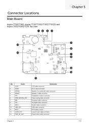
..., Aspire 7735/7735G/7735Z/7735ZG and Aspire 7535/7535G/7235 Top View Chapter 5 No. 1 2 3 4 5 6 7 8 9 10 11 12 13 Code LCD1 DCIN1 SPKR2 SPKR1 FP1 PWR_SAVING_CN1 KB1 TP1 MDC1 USB_CN1 RTC1 LAUN_CH1 PWE_BT_CN1 Connector LCD cable connector DC-in cable connector Speaker 2 or subwoofer cable connector Speaker 1 cable connector Fingerprint or button connector Power saving cable connector Keyboard cable connector Touchpad cable...
..., Aspire 7735/7735G/7735Z/7735ZG and Aspire 7535/7535G/7235 Top View Chapter 5 No. 1 2 3 4 5 6 7 8 9 10 11 12 13 Code LCD1 DCIN1 SPKR2 SPKR1 FP1 PWR_SAVING_CN1 KB1 TP1 MDC1 USB_CN1 RTC1 LAUN_CH1 PWE_BT_CN1 Connector LCD cable connector DC-in cable connector Speaker 2 or subwoofer cable connector Speaker 1 cable connector Fingerprint or button connector Power saving cable connector Keyboard cable connector Touchpad cable...
Acer Aspire 7535 Notebook Service Guide
Page 133
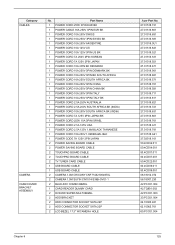
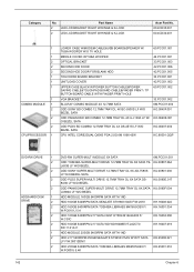
...JAPAN 2 POWER SAVING BOARD CABLE 2 POWER SAVING BOARD CABLE 2 TOUCHPAD BOARD CABLE 2 TOUCHPAD BOARD CABLE 2 TV TUNER CARD CABLE 1 USB BOARD CABLE 1 USB BOARD CABLE 2 CAMERA 1.0M CHICONY ...CNF714821004970L 2 CAMERA 1.0M SUYIN CN1014-S36B-OV01-1 2 BLUE-RAY COMBO BEZEL 1 CARD READER DUMMY CARD 2 DVD-RW SUPER-MULTI BEZEL 2 HDD BRACKET 2 HDD CONNECTOR SOCKET SATA 22P 2 HDD CONNECTOR SOCKET SATA 22P 2 LCD BEZEL 17.3" W/CAMERA HOLE Acer...
...JAPAN 2 POWER SAVING BOARD CABLE 2 POWER SAVING BOARD CABLE 2 TOUCHPAD BOARD CABLE 2 TOUCHPAD BOARD CABLE 2 TV TUNER CARD CABLE 1 USB BOARD CABLE 1 USB BOARD CABLE 2 CAMERA 1.0M CHICONY ...CNF714821004970L 2 CAMERA 1.0M SUYIN CN1014-S36B-OV01-1 2 BLUE-RAY COMBO BEZEL 1 CARD READER DUMMY CARD 2 DVD-RW SUPER-MULTI BEZEL 2 HDD BRACKET 2 HDD CONNECTOR SOCKET SATA 22P 2 HDD CONNECTOR SOCKET SATA 22P 2 LCD BEZEL 17.3" W/CAMERA HOLE Acer...
Acer Aspire 7535 Notebook Service Guide
Page 134
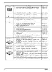
....3" IMR BLUE W/ANTENNA*2 & LOGO NONE 3G 2 LCD COVER 17.3" IMR BLUE W/ANTENNA*3 & LOGO NONE 3G Acer Part No. 60.PCC01.005 60.PCC01.006 2 LED LCD BRACKET LEFT W/HINGE & DC-IN CABLE 120W 2 LED LCD BRACKET LEFT W/HINGE & DC-IN CABLE 120W 2 LED LCD BRACKET RIGHT W/HINGE & K-LOCK 2 LED LCD BRACKET RIGHT W/HINGE & K-LOCK 60.4CD37.001 60...
....3" IMR BLUE W/ANTENNA*2 & LOGO NONE 3G 2 LCD COVER 17.3" IMR BLUE W/ANTENNA*3 & LOGO NONE 3G Acer Part No. 60.PCC01.005 60.PCC01.006 2 LED LCD BRACKET LEFT W/HINGE & DC-IN CABLE 120W 2 LED LCD BRACKET LEFT W/HINGE & DC-IN CABLE 120W 2 LED LCD BRACKET RIGHT W/HINGE & K-LOCK 2 LED LCD BRACKET RIGHT W/HINGE & K-LOCK 60.4CD37.001 60...
Acer Aspire 7535 Notebook Service Guide
Page 142
... LCD COVER 17.3" IMR BLUE W/ANTENNA*3 & LOGO NONE 3G Acer Part No. 42.PCC01.004 42.TQ901.003 42.PCC01.003 33.PCC01.004 22.10300.481 62.10065.761 60.PCC01.004 60.PCC01.005 60.PCC01.006 2 LED LCD BRACKET LEFT W/HINGE & DC-IN CABLE 90W 2 LED LCD BRACKET LEFT W/HINGE & DC-IN CABLE... 90W 2 LED LCD BRACKET RIGHT W/HINGE...
... LCD COVER 17.3" IMR BLUE W/ANTENNA*3 & LOGO NONE 3G Acer Part No. 42.PCC01.004 42.TQ901.003 42.PCC01.003 33.PCC01.004 22.10300.481 62.10065.761 60.PCC01.004 60.PCC01.005 60.PCC01.006 2 LED LCD BRACKET LEFT W/HINGE & DC-IN CABLE 90W 2 LED LCD BRACKET LEFT W/HINGE & DC-IN CABLE... 90W 2 LED LCD BRACKET RIGHT W/HINGE...
Acer Aspire 7535 Notebook Service Guide
Page 149
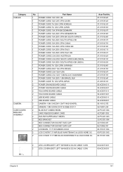
... BLACK TAIWANESE POWER CORD 10A 250V 1.8M BRAZIL BLK POWER CODE 7A 125V 2PIN JAPAN POWER SAVING BOARD CABLE POWER SAVING BOARD CABLE TOUCHPAD BOARD CABLE TOUCHPAD BOARD CABLE USB BOARD CABLE USB BOARD CABLE CAMERA 1.0M CHICONY CNF714821004970L CAMERA 1.0M SUYIN CN1014-S36B-OV01-1 BLUE-RAY COMBO BEZEL CARD READER DUMMY ...MULTI BEZEL HDD BRACKET HDD CONNECTOR SOCKET SATA 22P HDD CONNECTOR SOCKET SATA 22P LCD BEZEL 17.3" W/CAMERA HOLE LCD COVER17.3" IMR BLUE W/ANTENNA*2 & LOGO NONE 3G LCD COVER 17.3" IMR BLUE W/ANTENNA*3 & LOGO NONE 3G Acer Part No. 27.01518.641 27.01518.521 27.01518.531 27.01518....
... BLACK TAIWANESE POWER CORD 10A 250V 1.8M BRAZIL BLK POWER CODE 7A 125V 2PIN JAPAN POWER SAVING BOARD CABLE POWER SAVING BOARD CABLE TOUCHPAD BOARD CABLE TOUCHPAD BOARD CABLE USB BOARD CABLE USB BOARD CABLE CAMERA 1.0M CHICONY CNF714821004970L CAMERA 1.0M SUYIN CN1014-S36B-OV01-1 BLUE-RAY COMBO BEZEL CARD READER DUMMY ...MULTI BEZEL HDD BRACKET HDD CONNECTOR SOCKET SATA 22P HDD CONNECTOR SOCKET SATA 22P LCD BEZEL 17.3" W/CAMERA HOLE LCD COVER17.3" IMR BLUE W/ANTENNA*2 & LOGO NONE 3G LCD COVER 17.3" IMR BLUE W/ANTENNA*3 & LOGO NONE 3G Acer Part No. 27.01518.641 27.01518.521 27.01518.531 27.01518....
Acer Aspire 7535 Notebook Service Guide
Page 150
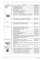
Category No. 2 2 Part Name LED LCD BRACKET RIGHT W/HINGE & K-LOCK LED LCD BRACKET RIGHT W/HINGE & K-LOCK Acer Part No. 60.4CD35.001 60.4CD32.001 1 1 2 2 2 1 1 1 1 COMBO MODULE 1 2 2 2 CPU/PROCESSOR 1 LOWER CASE W/MODEM CABLE&USB BOARD&SPEAKER W/ TUBA WOOFER W/O TV HOLE MIDDLE COVER W/TUBA WOOFER OPTICAL BRACKET SECOND HDD DOOR SECOND HDD DOOR FOR BLANK HDD...
Category No. 2 2 Part Name LED LCD BRACKET RIGHT W/HINGE & K-LOCK LED LCD BRACKET RIGHT W/HINGE & K-LOCK Acer Part No. 60.4CD35.001 60.4CD32.001 1 1 2 2 2 1 1 1 1 COMBO MODULE 1 2 2 2 CPU/PROCESSOR 1 LOWER CASE W/MODEM CABLE&USB BOARD&SPEAKER W/ TUBA WOOFER W/O TV HOLE MIDDLE COVER W/TUBA WOOFER OPTICAL BRACKET SECOND HDD DOOR SECOND HDD DOOR FOR BLANK HDD...


