
Quick Start Guide
Page 5
.... 4 Speakers Left and right speakers deliver stereo audio output. 5 Keyboard For entering data into your hands when you use the computer. 9 HDD Indicates when the hard disk drive is activated. English 5 # Icon Item Description 2 Display screen Also called Liquid-Crystal Display (LCD), displays computer output. 3 Touchpad toggle Turns the internal touchpad on...
.... 4 Speakers Left and right speakers deliver stereo audio output. 5 Keyboard For entering data into your hands when you use the computer. 9 HDD Indicates when the hard disk drive is activated. English 5 # Icon Item Description 2 Display screen Also called Liquid-Crystal Display (LCD), displays computer output. 3 Touchpad toggle Turns the internal touchpad on...
Quick Start Guide
Page 10
... 16:9 aspect ratio Mobile Intel® GL40 Express Chipset 2.5" hard disk drive DVD-Super Multi double-layer drive Multi-in-1 card reader Two built-in stereo speakers High-definition audio support MS-Sound compatible Integrated Acer Crystal Eye webcam* WLAN: • Acer InviLink™ 802.11b/g/Draft-N* • Acer InviLink™ 802.11b/g* LAN: Fast Ethernet;
... 16:9 aspect ratio Mobile Intel® GL40 Express Chipset 2.5" hard disk drive DVD-Super Multi double-layer drive Multi-in-1 card reader Two built-in stereo speakers High-definition audio support MS-Sound compatible Integrated Acer Crystal Eye webcam* WLAN: • Acer InviLink™ 802.11b/g/Draft-N* • Acer InviLink™ 802.11b/g* LAN: Fast Ethernet;

Service Guide
Page 7
Table of Contents System Specifications 1 Features 1 System Block Diagram 3 Your Acer Notebook tour 4 Front View 4 Closed Front View 5 Rear View 6 Left View 6 Right View 7 Bottom View 7 Indicators 8 TouchPad Basics 9 Using the Keyboard 10 Lock Keys and ... the Battery Pack 46 Removing the SD Dummy Card 47 Removing the Lower Covers 48 Removing the Optical Drive Module 49 Removing the DIMM Modules 51 Removing the WLAN Module 52 Removing the Hard Disk Drive Module 54 Main Unit Disassembly Process 56 Main Unit Disassembly Flowchart 56 Removing the Switch Cover 57...
Table of Contents System Specifications 1 Features 1 System Block Diagram 3 Your Acer Notebook tour 4 Front View 4 Closed Front View 5 Rear View 6 Left View 6 Right View 7 Bottom View 7 Indicators 8 TouchPad Basics 9 Using the Keyboard 10 Lock Keys and ... the Battery Pack 46 Removing the SD Dummy Card 47 Removing the Lower Covers 48 Removing the Optical Drive Module 49 Removing the DIMM Modules 51 Removing the WLAN Module 52 Removing the Hard Disk Drive Module 54 Main Unit Disassembly Process 56 Main Unit Disassembly Flowchart 56 Removing the Switch Cover 57...

Service Guide
Page 8
... the Power Board 106 Replacing the Upper Cover 106 Replacing the LCD Module 110 Replacing the Keyboard 115 Replacing the Switch Cover 116 Replacing the Hard Disk Drive Module 116 Replacing the WLAN Module 118 Replacing the DIMM Modules 118 Replacing the ODD Module 119 Replacing the Lower Covers 119 Replacing the...
... the Power Board 106 Replacing the Upper Cover 106 Replacing the LCD Module 110 Replacing the Keyboard 115 Replacing the Switch Cover 116 Replacing the Hard Disk Drive Module 116 Replacing the WLAN Module 118 Replacing the DIMM Modules 118 Replacing the ODD Module 119 Replacing the Lower Covers 119 Replacing the...

Service Guide
Page 11
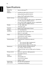
...* Display • • 17" HD+ 1600 x 900 16:9 aspect ratio Graphics • Mobile Intel® GL40 Express Chipset Storage subsystem • 2.5" hard disk drive • DVD-Super Multi double-layer drive • Multi-in-1 card reader Audio • • • Two built-in stereo speakers High-definition audio support MS-Sound compatible Dimensions...
...* Display • • 17" HD+ 1600 x 900 16:9 aspect ratio Graphics • Mobile Intel® GL40 Express Chipset Storage subsystem • 2.5" hard disk drive • DVD-Super Multi double-layer drive • Multi-in-1 card reader Audio • • • Two built-in stereo speakers High-definition audio support MS-Sound compatible Dimensions...
Service Guide
Page 15
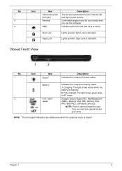
... mode. 2 5-in-1 card Accepts Secure Digital (SD), MultiMediaCard reader (MMC), Memory Stick (MS), Memory Stick PRO (MS PRO), xDPicture Card (xD). Indicates when the hard disk drive is charging. 2. Charging: The light shows amber when the battery is active. Only one card can operate at any given time. NOTE: 1 The front panel...
... mode. 2 5-in-1 card Accepts Secure Digital (SD), MultiMediaCard reader (MMC), Memory Stick (MS), Memory Stick PRO (MS PRO), xDPicture Card (xD). Indicates when the hard disk drive is charging. 2. Charging: The light shows amber when the battery is active. Only one card can operate at any given time. NOTE: 1 The front panel...

Service Guide
Page 18
... fan prolonged use. compartment 7 Ventilation slots Enable the computer to -read status indicators. Fully charged: The light shows green when in position. 4 Hard disk bay- Indicates when the hard disk drive is charging. 2. Lights up when Caps Lock is activated. Battery HDD Num Lock Caps Lock Indicates the computer's battery status. Lights up...
... fan prolonged use. compartment 7 Ventilation slots Enable the computer to -read status indicators. Fully charged: The light shows green when in position. 4 Hard disk bay- Indicates when the hard disk drive is charging. 2. Lights up when Caps Lock is activated. Battery HDD Num Lock Caps Lock Indicates the computer's battery status. Lights up...

Service Guide
Page 26
Hard Disk Drive Interface Item Vendor & Model Name Seagate ST9500325AS ST9250315AS Capacity (MB) 500, 250 Bytes per sector 512 Data heads 4, 2 Drive Format Disks 2, 1 Spindle speed (RPM) 5400 Performance Specifications Buffer size 8 MB Interface SATA Internal transfer rate (Mbits/sec, max) I/O data transfer rate (Mbytes/sec max) ...
Hard Disk Drive Interface Item Vendor & Model Name Seagate ST9500325AS ST9250315AS Capacity (MB) 500, 250 Bytes per sector 512 Data heads 4, 2 Drive Format Disks 2, 1 Spindle speed (RPM) 5400 Performance Specifications Buffer size 8 MB Interface SATA Internal transfer rate (Mbits/sec, max) I/O data transfer rate (Mbytes/sec max) ...

Service Guide
Page 33
... startup to skip certain tests while booting, decreasing the time needed to factory defaults. The function allows the user to create a hidden partition on hard disc drive to store operation system and restore the system to boot the system. Main The Main screen allows the user to 23. Enables, disables the system...
... startup to skip certain tests while booting, decreasing the time needed to factory defaults. The function allows the user to create a hidden partition on hard disc drive to store operation system and restore the system to boot the system. Main The Main screen allows the user to 23. Enables, disables the system...

Service Guide
Page 41
... Item F5/F6 Change Values F9 Setup Default Select Menu Enter Select SubMenu F10 Save and Exit Chapter 2 31 Bootable devices includes the USB diskette drives, the onboard hard disk drive and the DVD drive in the module bay. Network Boot : Atheros Boot Agent 5.
... Item F5/F6 Change Values F9 Setup Default Select Menu Enter Select SubMenu F10 Save and Exit Chapter 2 31 Bootable devices includes the USB diskette drives, the onboard hard disk drive and the DVD drive in the module bay. Network Boot : Atheros Boot Agent 5.

Service Guide
Page 64
Removing the Hard Disk Drive Module 1. Lift the HDD Module clear of the arrow to device, avoid pressing down on it or placing heavy objects on page 48. 2. Using the pull-tab, slide the HDD Module in the direction of the HDD bay. NOTE: To prevent damage to disconnect the interface. 3. See "Removing the Lower Covers" on top of it. 54 Chapter 3
Removing the Hard Disk Drive Module 1. Lift the HDD Module clear of the arrow to device, avoid pressing down on it or placing heavy objects on page 48. 2. Using the pull-tab, slide the HDD Module in the direction of the HDD bay. NOTE: To prevent damage to disconnect the interface. 3. See "Removing the Lower Covers" on top of it. 54 Chapter 3

Service Guide
Page 126
Place the HDD in the HDD carrier. 2. Replacing the Hard Disk Drive Module 1. Place the Switch Cover left side first on to snap the Switch Cover into place. Press down as indicated to the Upper Cover. 2. Replace the four screws (two each side) to secure the carrier. 116 Chapter 3 Replacing the Switch Cover 1.
Place the HDD in the HDD carrier. 2. Replacing the Hard Disk Drive Module 1. Place the Switch Cover left side first on to snap the Switch Cover into place. Press down as indicated to the Upper Cover. 2. Replace the four screws (two each side) to secure the carrier. 116 Chapter 3 Replacing the Switch Cover 1.

Service Guide
Page 146
... radiation, electrostatic discharge, or software errors. Rerun the test to do the following devices: • Non-Acer devices • Printer, mouse, and other external devices • Battery pack • Hard disk drive • DIMM • CD-ROM/Diskette drive Module • PC Cards 4. Power-on page 124.): 1. Do not replace a non-defective FRU: •...
... radiation, electrostatic discharge, or software errors. Rerun the test to do the following devices: • Non-Acer devices • Printer, mouse, and other external devices • Battery pack • Hard disk drive • DIMM • CD-ROM/Diskette drive Module • PC Cards 4. Power-on page 124.): 1. Do not replace a non-defective FRU: •...

Service Guide
Page 167
... 575 PGA 2.0G 1M 667 MV CPU Intel Celeron 585 PGA 2.16G 1M 667 MV CPU Intel Celeron 900 PGA 2.2G 1M 800 35W HDD/HARD DISK DRIVE HDD SEAGATE 2.5" 5400rpm 160GB ST9160310AS Crockett SATA LF F/W:0303 HDD TOSHIBA 2.5" 5400rpm 160GB MK1655GSX Libra SATA LF F/W: FG011J HDD HGST 2.5" 5400rpm 160GB HTS543216L9A300 Falcon...
... 575 PGA 2.0G 1M 667 MV CPU Intel Celeron 585 PGA 2.16G 1M 667 MV CPU Intel Celeron 900 PGA 2.2G 1M 800 35W HDD/HARD DISK DRIVE HDD SEAGATE 2.5" 5400rpm 160GB ST9160310AS Crockett SATA LF F/W:0303 HDD TOSHIBA 2.5" 5400rpm 160GB MK1655GSX Libra SATA LF F/W: FG011J HDD HGST 2.5" 5400rpm 160GB HTS543216L9A300 Falcon...

Service Guide
Page 197
... hotkeys 12 E EasyTouch Failure 134 External Module Disassembly Flowchart 45 F Features 1 Flash Utility 33 FPC Cable Removing 86 FRU (Field Replaceable Unit) List 151 H Hard Disk Drive Removing 54 Replacing 116 HDTV Switch Failure 135 Hibernation mode hotkey 12 Hot Keys 10 I Indicators 8 Intermittent Problems 136 Internal Microphone Failure 129 Internal Speaker...
... hotkeys 12 E EasyTouch Failure 134 External Module Disassembly Flowchart 45 F Features 1 Flash Utility 33 FPC Cable Removing 86 FRU (Field Replaceable Unit) List 151 H Hard Disk Drive Removing 54 Replacing 116 HDTV Switch Failure 135 Hibernation mode hotkey 12 Hot Keys 10 I Indicators 8 Intermittent Problems 136 Internal Microphone Failure 129 Internal Speaker...


