
Quick Start Guide
Page 6
... operate at any given time. 1. Fully charged: The light shows blue when in AC mode. 2 Multi-in-1 Accepts Secure Digital (SD), MultiMediaCard card (MMC), Memory Stick (MS), Memory Stick PRO (MS reader PRO), xD-Picture Card (xD). Volume down Decreases the screen brightness. Battery1 Indicates the computer's battery status. 1. Brightness up Increases...
... operate at any given time. 1. Fully charged: The light shows blue when in AC mode. 2 Multi-in-1 Accepts Secure Digital (SD), MultiMediaCard card (MMC), Memory Stick (MS), Memory Stick PRO (MS reader PRO), xD-Picture Card (xD). Volume down Decreases the screen brightness. Battery1 Indicates the computer's battery status. 1. Brightness up Increases...

Quick Start Guide
Page 9
.... 2 Battery release latch Releases the battery for certain models only). 5 Hard disk bay-Main Houses the computer's hard disk (secured with screws). 6 Memory compartment Houses the computer's main memory. 7 Ventilation slots and Enable the computer to stay cool, even cooling fan after prolonged use. Secondary Houses the computer's hard disk (secured with...
.... 2 Battery release latch Releases the battery for certain models only). 5 Hard disk bay-Main Houses the computer's hard disk (secured with screws). 6 Memory compartment Houses the computer's main memory. 7 Ventilation slots and Enable the computer to stay cool, even cooling fan after prolonged use. Secondary Houses the computer's hard disk (secured with...
Quick Start Guide
Page 10
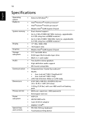
...;* 99-/100-/103-key keyboard Touchpad pointing device 10 English Specifications Operating • system Platform • • • System memory • • • Display • • Graphics • Storage • subsystem • • Audio &#...memory, upgradeable to 4 GB using two soDIMM modules* 17" HD+ 1600 x 900 16:9 aspect ratio Mobile Intel® GL40 Express Chipset 2.5" hard disk drive DVD-Super Multi double-layer drive Multi-in-1 card reader Two built-in stereo speakers High-definition audio support MS-Sound compatible Integrated Acer...
...;* 99-/100-/103-key keyboard Touchpad pointing device 10 English Specifications Operating • system Platform • • • System memory • • • Display • • Graphics • Storage • subsystem • • Audio &#...memory, upgradeable to 4 GB using two soDIMM modules* 17" HD+ 1600 x 900 16:9 aspect ratio Mobile Intel® GL40 Express Chipset 2.5" hard disk drive DVD-Super Multi double-layer drive Multi-in-1 card reader Two built-in stereo speakers High-definition audio support MS-Sound compatible Integrated Acer...

Service Guide
Page 5
...the functionality of a machine (e.g. These LOCALIZED FEATURES will not be covered in this printed Service Guide. If, for Acer's "global" product offering. For ACER-AUTHORIZED SERVICE PROVIDERS, your regional offices or the responsible personnel/channel to provide you should check the most up-to the... note WHEN ORDERING FRU PARTS, that you with all technical information relating to -date information available on card, modem, or extra memory capability). Preface Before using this information and the product it will NOT be noted in the printed Service Guide. To better fit local...
...the functionality of a machine (e.g. These LOCALIZED FEATURES will not be covered in this printed Service Guide. If, for Acer's "global" product offering. For ACER-AUTHORIZED SERVICE PROVIDERS, your regional offices or the responsible personnel/channel to provide you should check the most up-to the... note WHEN ORDERING FRU PARTS, that you with all technical information relating to -date information available on card, modem, or extra memory capability). Preface Before using this information and the product it will NOT be noted in the printed Service Guide. To better fit local...
Service Guide
Page 9
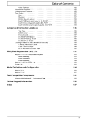
Table of Contents Other Failures 135 Intermittent Problems 136 Undetermined Problems 136 Post Codes 137 Sec 137 Memory 137 BDS & Specific action 138 Each PEIM entry point used in 80_PORT 140 Each Driver entry point used in 80_PORT 140 Each... by Crisis Disk 150 FRU (Field Replaceable Unit) List 151 Aspire 7715Z/7315 Exploded Diagrams 152 Main Assembly 152 Base Assembly 153 Rear Assembly 154 Aspire 7715Z/7315 FRU List 155 Screw List 163 Model Definition and Configuration 164 Aspire 7315 165 Aspire 7715Z 167 Test Compatible Components 181 Microsoft® Windows® 7 ...
Table of Contents Other Failures 135 Intermittent Problems 136 Undetermined Problems 136 Post Codes 137 Sec 137 Memory 137 BDS & Specific action 138 Each PEIM entry point used in 80_PORT 140 Each Driver entry point used in 80_PORT 140 Each... by Crisis Disk 150 FRU (Field Replaceable Unit) List 151 Aspire 7715Z/7315 Exploded Diagrams 152 Main Assembly 152 Base Assembly 153 Rear Assembly 154 Aspire 7715Z/7315 FRU List 155 Screw List 163 Model Definition and Configuration 164 Aspire 7315 165 Aspire 7715Z 167 Test Compatible Components 181 Microsoft® Windows® 7 ...

Service Guide
Page 11
...mobile processor* • Intel® Celeron® mobile processor* • Mobile Intel® GL40 Express Chipset System Memory • Dual-channel support • Up to 2 GB of DDR2 667 MHz memory, upgradeable to 4 GB using two soDIMM modules* • Up to 4 GB using two soDIMM modules* Display &#... x 26.8/39.6 (H) mm (16 x 10.45 x 1.04/1.54 inches) Chapter 1 1 System Specifications Chapter 1 Features Below is a brief summary of DDR3 1066 MHz memory, upgradeable to 2 GB of the computer's many features: NOTE: Items denoted with an (*) are only available for selected models.
...mobile processor* • Intel® Celeron® mobile processor* • Mobile Intel® GL40 Express Chipset System Memory • Dual-channel support • Up to 2 GB of DDR2 667 MHz memory, upgradeable to 4 GB using two soDIMM modules* • Up to 4 GB using two soDIMM modules* Display &#... x 26.8/39.6 (H) mm (16 x 10.45 x 1.04/1.54 inches) Chapter 1 1 System Specifications Chapter 1 Features Below is a brief summary of DDR3 1066 MHz memory, upgradeable to 2 GB of the computer's many features: NOTE: Items denoted with an (*) are only available for selected models.
Service Guide
Page 15
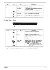
Fully charged: The light shows green when in AC mode. 2 5-in-1 card Accepts Secure Digital (SD), MultiMediaCard reader (MMC), Memory Stick (MS), Memory Stick PRO (MS PRO), xDPicture Card (xD). Lights up when Num Lock is activated. Battery1 Indicates the computer's battery status. 1. NOTE: Push to remove/install ...
Fully charged: The light shows green when in AC mode. 2 5-in-1 card Accepts Secure Digital (SD), MultiMediaCard reader (MMC), Memory Stick (MS), Memory Stick PRO (MS PRO), xDPicture Card (xD). Lights up when Num Lock is activated. Battery1 Indicates the computer's battery status. 1. NOTE: Push to remove/install ...

Service Guide
Page 18
No. 3 Icon Item Battery lock Description Locks the battery in AC mode. Houses the computer's hard disk (secured Secondary with screws). 6 Memory Houses the computer's main memory. Note: Do not cover or obstruct the fan opening. Battery HDD Num Lock Caps Lock Indicates the computer's battery status. Indicates when the hard disk ...
No. 3 Icon Item Battery lock Description Locks the battery in AC mode. Houses the computer's hard disk (secured Secondary with screws). 6 Memory Houses the computer's main memory. Note: Do not cover or obstruct the fan opening. Battery HDD Num Lock Caps Lock Indicates the computer's battery status. Indicates when the hard disk ...

Service Guide
Page 24
... Item BIOS vendor BIOS Version BIOS ROM type Features ICH9-M BGA-676 System Memory Item Memory controller Memory size DIMM socket number Supports memory size per socket Supports maximum memory size Supports DIMM type Supports DIMM Speed Supports DIMM voltage Specification Specification Insyde BIOS... V0.06-T02 Flash • Flash ROM 1MB • Supports ISIPP • Supports Acer UI • Supports multi-boot ...
... Item BIOS vendor BIOS Version BIOS ROM type Features ICH9-M BGA-676 System Memory Item Memory controller Memory size DIMM socket number Supports memory size per socket Supports maximum memory size Supports DIMM type Supports DIMM Speed Supports DIMM voltage Specification Specification Insyde BIOS... V0.06-T02 Flash • Flash ROM 1MB • Supports ISIPP • Supports Acer UI • Supports multi-boot ...

Service Guide
Page 25
...You may combine DIMMs with various capacities to form other combinations. On above table, the configuration of slot 1 and slot 2 could be reversed. Memory Combinations Slot 1 0MB 0MB 0MB 512MB 512MB 512MB 1024MB 1024MB 1024MB 1024MB 2048MB 2048MB 2048MB 2048MB 512MB 1024MB 2048MB 512MB 1024MB 2048MB 0MB 512MB 1024MB... 2048MB 0MB 512MB 1024MB 2048MB Slot 2 Total Memory 512MB 1024MB 2048MB 1024MB 1536MB 2560MB 1024MB 1536MB 2048MB 3072MB 2048MB 2560MB 3072MB 4096MB NOTE: Above table lists some system...
...You may combine DIMMs with various capacities to form other combinations. On above table, the configuration of slot 1 and slot 2 could be reversed. Memory Combinations Slot 1 0MB 0MB 0MB 512MB 512MB 512MB 1024MB 1024MB 1024MB 1024MB 2048MB 2048MB 2048MB 2048MB 512MB 1024MB 2048MB 512MB 1024MB 2048MB 0MB 512MB 1024MB... 2048MB 0MB 512MB 1024MB 2048MB Slot 2 Total Memory 512MB 1024MB 2048MB 1024MB 1536MB 2560MB 1024MB 1536MB 2048MB 3072MB 2048MB 2560MB 3072MB 4096MB NOTE: Above table lists some system...

Service Guide
Page 27
... (DL) 8.5GB (Ver. 3.0) V2.0 & 2.1 &2.2. Sustained: 11.08 Mbytes/s (8x) max. Super-Multi Drive Module Item Vendor & model name Performance Specification Transfer rate (MB/ sec) Buffer Memory Interface Applicable disc formats Loading mechanism Power Requirement Input Voltage HLDS GT20N Specification Sony AD7580S With CD Diskette With DVD Diskette With CD Diskette With...
... (DL) 8.5GB (Ver. 3.0) V2.0 & 2.1 &2.2. Sustained: 11.08 Mbytes/s (8x) max. Super-Multi Drive Module Item Vendor & model name Performance Specification Transfer rate (MB/ sec) Buffer Memory Interface Applicable disc formats Loading mechanism Power Requirement Input Voltage HLDS GT20N Specification Sony AD7580S With CD Diskette With DVD Diskette With CD Diskette With...

Service Guide
Page 33
... to set the system time and date as well as enable and disable boot option and recovery. Parameter System Time System Date Total Memory Video Memory Quick Boot Network Boot F12 Boot Menu D2D Recovery SATA Mode Description Sets the system time. Format/Option Format: HH:MM:SS (... Main screen allows the user to factory defaults. InsydeH20 Setup Utility Information Main Advanced Security Power Boot Exit Rev. 3.5 System Time: System Date: Total Memory: Video Memory: Quick Boot Network Boot F12 Boot Menu D2D Recovery SATA Mode [19:10:59] [01/09/2009] 4095 MB 512 MB [Enabled] [Enabled...
... to set the system time and date as well as enable and disable boot option and recovery. Parameter System Time System Date Total Memory Video Memory Quick Boot Network Boot F12 Boot Menu D2D Recovery SATA Mode Description Sets the system time. Format/Option Format: HH:MM:SS (... Main screen allows the user to factory defaults. InsydeH20 Setup Utility Information Main Advanced Security Power Boot Exit Rev. 3.5 System Time: System Date: Total Memory: Video Memory: Quick Boot Network Boot F12 Boot Menu D2D Recovery SATA Mode [19:10:59] [01/09/2009] 4095 MB 512 MB [Enabled] [Enabled...

Service Guide
Page 35
... the USB Configuration menu. Express Card PCI EXpress Root Port 1 ~ 6 ASF Configuration Submenu Items • Render Standby • IGD-Device2, Function1 • IGD-Pre-allocat Memory • IGD-DVMT Size • Clock Chip Initialize • Enabled CK SSC • IGD-Boot Type • IGD-LCD Panel Type • IGD-TV •...
... the USB Configuration menu. Express Card PCI EXpress Root Port 1 ~ 6 ASF Configuration Submenu Items • Render Standby • IGD-Device2, Function1 • IGD-Pre-allocat Memory • IGD-DVMT Size • Clock Chip Initialize • Enabled CK SSC • IGD-Boot Type • IGD-LCD Panel Type • IGD-TV •...
Service Guide
Page 43
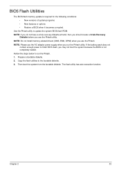
NOTE: Do not install memory-related drivers (XMS, EMS, DPMI) when you may not boot the system because the BIOS is required for the following conditions: • New versions of ... becomes corrupted. Prepare a bootable diskette. 2. If the battery pack does not contain enough power to run the Phlash utility. BIOS Flash Utilities The BIOS flash memory update is not completely loaded. Use the Phlash utility to the bootable diskette. 3. Then boot the system from the bootable diskette. The flash utility has...
NOTE: Do not install memory-related drivers (XMS, EMS, DPMI) when you may not boot the system because the BIOS is required for the following conditions: • New versions of ... becomes corrupted. Prepare a bootable diskette. 2. If the battery pack does not contain enough power to run the Phlash utility. BIOS Flash Utilities The BIOS flash memory update is not completely loaded. Use the Phlash utility to the bootable diskette. 3. Then boot the system from the bootable diskette. The flash utility has...
Service Guide
Page 50
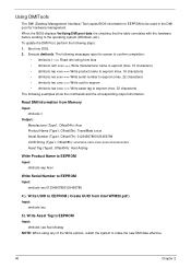
...xxxx ==> Write uuid to eeprom • dmitools /wa xxxx ==> Write asset tag to EEPROM ( Create UUID from Memory Input: dmitools /r Output: Manufacturer (Type1, Offset04h): Acer Product Name (Type1, Offset05h): TravelMate xxxxx Serial Number (Type1, Offset07h): 01234567890123456789 UUID String (Type1, Offset08h): xxxxxxxx-xxxx-...xxxx-xxxx-xxxxxxxxxxxx Asset Tag (Type3, Offset04h): Acet Asstag Write Product Name to EEPROM Input: dmitools /wp Acer Write Serial Number to make the new DMI data effective. 40 Chapter 2 Using DMITools The DMI (Desktop Management Interface) Tool...
...xxxx ==> Write uuid to eeprom • dmitools /wa xxxx ==> Write asset tag to EEPROM ( Create UUID from Memory Input: dmitools /r Output: Manufacturer (Type1, Offset04h): Acer Product Name (Type1, Offset05h): TravelMate xxxxx Serial Number (Type1, Offset07h): 01234567890123456789 UUID String (Type1, Offset08h): xxxxxxxx-xxxx-...xxxx-xxxx-xxxxxxxxxxxx Asset Tag (Type3, Offset04h): Acet Asstag Write Product Name to EEPROM Input: dmitools /wp Acer Write Serial Number to make the new DMI data effective. 40 Chapter 2 Using DMITools The DMI (Desktop Management Interface) Tool...

Service Guide
Page 58
Remove the HDD cover as shown. Memory Cover HDD Cover Step Lower Covers Size M2.5*8 3. Carefully open the Memory Cover. 48 Chapter 3 Removing the Lower Covers 1. Quantity 3 Screw Type 4. See "Removing the Battery Pack" on page 46. 2. Remove the three screws securing the Memory and HDD Covers.
Remove the HDD cover as shown. Memory Cover HDD Cover Step Lower Covers Size M2.5*8 3. Carefully open the Memory Cover. 48 Chapter 3 Removing the Lower Covers 1. Quantity 3 Screw Type 4. See "Removing the Battery Pack" on page 46. 2. Remove the three screws securing the Memory and HDD Covers.

Service Guide
Page 129
Replacing the ODD Module 1. Secure the ODD bracket with the casing. flush with the two screws. Replace the Memory Cover as shown. Chapter 3 119 secure it is 4. Replacing the Lower Covers 1. Push the ODD Module into the tray, bottom edge first, to the ODD Module. 3. Replace the HDD Cover as shown. 2. Replace the single screw to ensure that the all the securing tabs are correctly located in the casing. Press the bezel into the ODD bay until it to 2. IMPORTANT: Press down around the perimeter of the covers to secure the Module.
Replacing the ODD Module 1. Secure the ODD bracket with the casing. flush with the two screws. Replace the Memory Cover as shown. Chapter 3 119 secure it is 4. Replacing the Lower Covers 1. Push the ODD Module into the tray, bottom edge first, to the ODD Module. 3. Replace the HDD Cover as shown. 2. Replace the single screw to ensure that the all the securing tabs are correctly located in the casing. Press the bezel into the ODD bay until it to 2. IMPORTANT: Press down around the perimeter of the covers to secure the Module.

Service Guide
Page 130
Push until the card clicks into the slot as shown. 2. Insert the SD Dummy Card into place and is flush with the casing. 120 Chapter 3 3. Replace the three screws to secure the covers in place. Memory Cover HDD Cover Replacing the SD Dummy Card 1.
Push until the card clicks into the slot as shown. 2. Insert the SD Dummy Card into place and is flush with the casing. 120 Chapter 3 3. Replace the three screws to secure the covers in place. Memory Cover HDD Cover Replacing the SD Dummy Card 1.

Service Guide
Page 135
...holding down the power button for specific model procedures. 2. Make sure the computer has power by pressing Fn+F5. Restart the computer. Reseat the memory modules. 7. Chapter 4 125 Disconnect power and all external devices including port replicators or docking stations. Remove the drives (see "Power On Issue...44). 8. No Display Issue If the Display doesn't work, perform the following actions one at a time to correct the problem. 1. Drain any memory cards and CD/DVD discs. If the Issue is no power, see "Disassembly Process" on page 124. 3. On this model). If the POST ...
...holding down the power button for specific model procedures. 2. Make sure the computer has power by pressing Fn+F5. Restart the computer. Reseat the memory modules. 7. Chapter 4 125 Disconnect power and all external devices including port replicators or docking stations. Remove the drives (see "Power On Issue...44). 8. No Display Issue If the Display doesn't work, perform the following actions one at a time to correct the problem. 1. Drain any memory cards and CD/DVD discs. If the Issue is no power, see "Disassembly Process" on page 124. 3. On this model). If the POST ...
Service Guide
Page 136
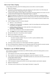
...; There are still lost, replace the cables. 4. See "Disassembly Process" on the desktop and select Personalize´ Display Settings. Reboot the computer. 2. d. Run the Windows Memory Diagnostic from the BIOS, the drive may reduce display brightness.
...; There are still lost, replace the cables. 4. See "Disassembly Process" on the desktop and select Personalize´ Display Settings. Reboot the computer. 2. d. Run the Windows Memory Diagnostic from the BIOS, the drive may reduce display brightness.


