Quick Start Guide
Page 3
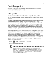
... Format (PDF) and comes preloaded on AcerSystem User Guide. Note: Viewing the file requires Adobe Reader. For instructions on how to be more on such subjects as Acer's Empowering Technology, using the keyboard, audio, etc. Your guides To help you use Adobe Reader, access the Help and Support menu. The Quick Guide introduces you to the basic features and functions of your computer can help you to use your notebook. This guide...
... Format (PDF) and comes preloaded on AcerSystem User Guide. Note: Viewing the file requires Adobe Reader. For instructions on how to be more on such subjects as Acer's Empowering Technology, using the keyboard, audio, etc. Your guides To help you use Adobe Reader, access the Help and Support menu. The Quick Guide introduces you to the basic features and functions of your computer can help you to use your notebook. This guide...
Quick Start Guide
Page 5
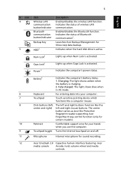
... hard disk drive is activated. Caps Lock1 Power1 Lights up when Num Lock is charging. 2. Battery1 Indicates the computer's battery status. 1. Charging: The light shows amber when the battery is activated. Indicates the status of wireless LAN button/indicator communication. The center button serves as Acer Bio Protection fingerprint reader supporting Acer FingerNav 4-way control function (only for certain models). 10 Palmrest Comfortable support area for your computer. 7 Touchpad Touch-sensitive pointing device which functions like a computer mouse. 8 Click buttons...
... hard disk drive is activated. Caps Lock1 Power1 Lights up when Num Lock is charging. 2. Battery1 Indicates the computer's battery status. 1. Charging: The light shows amber when the battery is activated. Indicates the status of wireless LAN button/indicator communication. The center button serves as Acer Bio Protection fingerprint reader supporting Acer FingerNav 4-way control function (only for certain models). 10 Palmrest Comfortable support area for your computer. 7 Touchpad Touch-sensitive pointing device which functions like a computer mouse. 8 Click buttons...

Quick Start Guide
Page 6
... the screen brightness. Turns the display screen backlight off to return. 1. Hotkey Icon + + Function System Properties Bluetooth + Sleep Description Starts System Properties for certain models). Enables/disables the Bluetooth function*. Press any key to save power. Turns the display screen backlight off to access most of the computer's controls like screen brightness, volume output. Keyboard backlight toggle Brightness up . Left and right speakers deliver stereo audio output. Turns Acer CineBoost Color Engine on and off . The front panel indicators are...
... the screen brightness. Turns the display screen backlight off to return. 1. Hotkey Icon + + Function System Properties Bluetooth + Sleep Description Starts System Properties for certain models). Enables/disables the Bluetooth function*. Press any key to save power. Turns the display screen backlight off to access most of the computer's controls like screen brightness, volume output. Keyboard backlight toggle Brightness up . Left and right speakers deliver stereo audio output. Turns Acer CineBoost Color Engine on and off . The front panel indicators are...
Quick Start Guide
Page 12
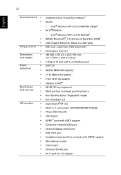
...-LAN ready BIOS user, supervisor, HDD passwords Kensington lock slot 383 (W) x 250 (D) x 26/37 (H) mm (15.1 x 9.9 x 1.03/1.5 inches) 2.8 kg (6.16 lbs.) with 6-cell battery pack ACPI 3.0 48.8 W 4400 mAh battery* 71 W 4800 mAh battery* 3-pin 90 W AC adapter ENERGY STAR®* 86-/87-/91-key keyboard Multi-gesture touchpad pointing device Acer Bio-Protection fingerprint reader Acer CineDash 2.0 ExpressCard®/54 slot Multi-in-1 card reader (SD/MMC/MS/MS PRO/xD) Three USB 2.0 ports...
...-LAN ready BIOS user, supervisor, HDD passwords Kensington lock slot 383 (W) x 250 (D) x 26/37 (H) mm (15.1 x 9.9 x 1.03/1.5 inches) 2.8 kg (6.16 lbs.) with 6-cell battery pack ACPI 3.0 48.8 W 4400 mAh battery* 71 W 4800 mAh battery* 3-pin 90 W AC adapter ENERGY STAR®* 86-/87-/91-key keyboard Multi-gesture touchpad pointing device Acer Bio-Protection fingerprint reader Acer CineDash 2.0 ExpressCard®/54 slot Multi-in-1 card reader (SD/MMC/MS/MS PRO/xD) Three USB 2.0 ports...
Service Guide
Page 7
... 10 TouchPad Basics (with fingerprint reader 11 Using the Keyboard 12 Lock Keys and embedded numeric keypad 12 Windows Keys 13 Hot Keys 14 Special Keys 15 Hardware Specifications and Configurations 16 System Utilities 23 BIOS Setup Utility 23 Navigating the BIOS Utility 23 Information 24 Main 25 Security 26 Boot 29 Exit 30 BIOS Flash Utilities 31 DOS Flash Utility 32 WinFlash Utility 34 Remove HDD/BIOS Password Utilities 35 Machine Disassembly and Replacement 41 Disassembly Requirements 41 General Information 42 Pre-disassembly Instructions 42 Disassembly Process...
... 10 TouchPad Basics (with fingerprint reader 11 Using the Keyboard 12 Lock Keys and embedded numeric keypad 12 Windows Keys 13 Hot Keys 14 Special Keys 15 Hardware Specifications and Configurations 16 System Utilities 23 BIOS Setup Utility 23 Navigating the BIOS Utility 23 Information 24 Main 25 Security 26 Boot 29 Exit 30 BIOS Flash Utilities 31 DOS Flash Utility 32 WinFlash Utility 34 Remove HDD/BIOS Password Utilities 35 Machine Disassembly and Replacement 41 Disassembly Requirements 41 General Information 42 Pre-disassembly Instructions 42 Disassembly Process...
Service Guide
Page 8
... Speaker Module 115 Replacing the Launch Board 117 Replacing the Media Board 119 Replacing the Upper Cover 120 Replacing the Keyboard 124 Replacing the WLAN Module 125 Replacing the DIMM Modules 127 Replacing the Hard Disk Drive Module 127 Replacing the ODD Module 128 Replacing the Lower Covers 129 Replacing the SD Dummy Card 129 Replacing the PCI Express Dummy Card 130 Replacing the Battery 130 Troubleshooting 131 Common Problems 131 Power On Issue 132 No Display Issue 133 Random Loss of BIOS Settings 134 LCD...
... Speaker Module 115 Replacing the Launch Board 117 Replacing the Media Board 119 Replacing the Upper Cover 120 Replacing the Keyboard 124 Replacing the WLAN Module 125 Replacing the DIMM Modules 127 Replacing the Hard Disk Drive Module 127 Replacing the ODD Module 128 Replacing the Lower Covers 129 Replacing the SD Dummy Card 129 Replacing the PCI Express Dummy Card 130 Replacing the Battery 130 Troubleshooting 131 Common Problems 131 Power On Issue 132 No Display Issue 133 Random Loss of BIOS Settings 134 LCD...
Service Guide
Page 16
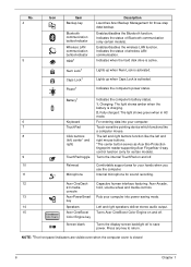
... key Screen blank Turns the display screen backlight off to return. NOTE: 1The front panel indicators are visible even when the computer cover is activated. Lights up when Caps Lock is active. Lights up when Num Lock is closed 6 Chapter 1 Indicates the status of wireless LAN communication. Indicates when the hard disk drive is activated. Battery1 Indicates the computer's battery status. 1. right) *The center button serves as Acer Bio-Protection fingerprint reader supporting Acer FingerNav 4-way control function (only for certain models). 9 TouchPad toggle Turns...
... key Screen blank Turns the display screen backlight off to return. NOTE: 1The front panel indicators are visible even when the computer cover is activated. Lights up when Caps Lock is active. Lights up when Num Lock is closed 6 Chapter 1 Indicates the status of wireless LAN communication. Indicates when the hard disk drive is activated. Battery1 Indicates the computer's battery status. 1. right) *The center button serves as Acer Bio-Protection fingerprint reader supporting Acer FingerNav 4-way control function (only for certain models). 9 TouchPad toggle Turns...

Service Guide
Page 24
... . Press any key to save power. Hotkey + + Icon Function System Properties Bluetooth Description Starts System Properties for displaying system information. Hot Keys The computer employs hotkeys or key combinations to access most of the computer's controls like screen brightness, volume output and the BIOS utility. Increases the sound volume. + < > Volume down Volume up Puts the computer in the hotkey combination. Turns the speakers on or off . Switches display output between the display screen, external monitor (if connected) and both. To activate hot keys, press...
... . Press any key to save power. Hotkey + + Icon Function System Properties Bluetooth Description Starts System Properties for displaying system information. Hot Keys The computer employs hotkeys or key combinations to access most of the computer's controls like screen brightness, volume output and the BIOS utility. Increases the sound volume. + < > Volume down Volume up Puts the computer in the hotkey combination. Turns the speakers on or off . Switches display output between the display screen, external monitor (if connected) and both. To activate hot keys, press...
Service Guide
Page 36
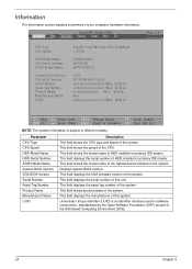
... Change Values F9 Setup Default Select Menu Enter Select SubMenu F10 Save and Exit NOTE: The system information is an identifier standard used in the system. This field displays the serial number of HDD installed on primary IDE master. This field displays the VGA firmware version of the system. Universally Unique Identifier (UUID) is subject to different models. This field shows the model name of HDD installed...
... Change Values F9 Setup Default Select Menu Enter Select SubMenu F10 Save and Exit NOTE: The system information is an identifier standard used in the system. This field displays the serial number of HDD installed on primary IDE master. This field displays the VGA firmware version of the system. Universally Unique Identifier (UUID) is subject to different models. This field shows the model name of HDD installed...
Service Guide
Page 39
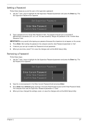
... password, the computer sets the User Password parameter to save the changes and exit the BIOS Setup Utility. Press Enter twice without typing anything in the "Enter New Password" field. When you have changed the settings, press u to "Clear". 4. Use the ↑ and ↓ keys to highlight the Set Supervisor Password parameter and press the Enter key. Type a password in the Enter New Password and Confirm New Password fields. Press Enter. Type the current password in the "Confirm New Password" field. Setting a Password Follow these steps: 1. Removing a Password...
... password, the computer sets the User Password parameter to save the changes and exit the BIOS Setup Utility. Press Enter twice without typing anything in the "Enter New Password" field. When you have changed the settings, press u to "Clear". 4. Use the ↑ and ↓ keys to highlight the Set Supervisor Password parameter and press the Enter key. Type a password in the Enter New Password and Confirm New Password fields. Press Enter. Type the current password in the "Confirm New Password" field. Setting a Password Follow these steps: 1. Removing a Password...

Service Guide
Page 40
... Password field and press Enter. 3. After setting the password, the computer sets the User Password parameter to highlight the Set Supervisor Password parameter and press the Enter key. The Set Password box appears. Type a password in the Enter New Password field. If desired, you are done, press F10 to save the changes and exit the BIOS Setup Utility. If the current password entered does not match the actual current password, the screen will display the following . Setup Warning Passwords...
... Password field and press Enter. 3. After setting the password, the computer sets the User Password parameter to highlight the Set Supervisor Password parameter and press the Enter key. The Set Password box appears. Type a password in the Enter New Password field. If desired, you are done, press F10 to save the changes and exit the BIOS Setup Utility. If the current password entered does not match the actual current password, the screen will display the following . Setup Warning Passwords...
Service Guide
Page 42
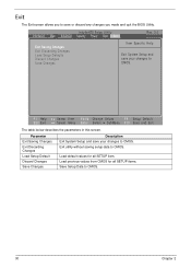
... Menu Enter Select SubMenu F10 Save and Exit The table below describes the parameters in this screen. Load default values for all SETUP item. Exit The Exit screen allows you made and quit the BIOS Utility. InsydeH20 Setup Utility Information Main Advanced Security Power Boot Exit Rev. 3.0 Exit Saving Changes Exit Discarding Changes Load Setup Defaults Discard Changes Save Changes Item Specific Help Exit System Setup and save your changes to CMOS...
... Menu Enter Select SubMenu F10 Save and Exit The table below describes the parameters in this screen. Load default values for all SETUP item. Exit The Exit screen allows you made and quit the BIOS Utility. InsydeH20 Setup Utility Information Main Advanced Security Power Boot Exit Rev. 3.0 Exit Saving Changes Exit Discarding Changes Load Setup Defaults Discard Changes Save Changes Item Specific Help Exit System Setup and save your changes to CMOS...
Service Guide
Page 143
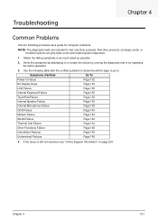
... Display Issue Page 133 LCD Failure Page 135 Internal Keyboard Failure Page 135 TouchPad Failure Page 136 Internal Speaker Failure Page 136 Internal Microphone Failure Page 138 ODD Failure Page 140 Modem Failure Page 143 WLAN Failure Page 143 Thermal Unit Failure Page 144 Other Functions Failure Page 145 Intermittent Failures Page 146 Undermined Failures Page 146 4. Troubleshooting Chapter 4 Common Problems Use...
... Display Issue Page 133 LCD Failure Page 135 Internal Keyboard Failure Page 135 TouchPad Failure Page 136 Internal Speaker Failure Page 136 Internal Microphone Failure Page 138 ODD Failure Page 140 Modem Failure Page 143 WLAN Failure Page 143 Thermal Unit Failure Page 144 Other Functions Failure Page 145 Intermittent Failures Page 146 Undermined Failures Page 146 4. Troubleshooting Chapter 4 Common Problems Use...
Service Guide
Page 145
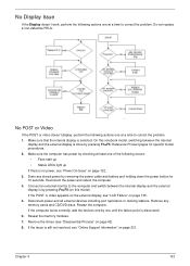
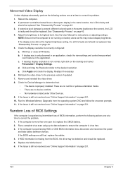
... memory cards and CD/DVD discs. Connect an external monitor to correct the problem. Restart the computer. If the Issue is by removing the power cable and battery and holding down the power button for specific model procedures. 2. Remove the drives (see "LCD Failure" on page 135. 5. Remove any stored power by pressing Fn+F5 (on page 132. 3. Do not replace a non-defective FRUs: No POST or Video If the POST or video doesn't display...
... memory cards and CD/DVD discs. Connect an external monitor to correct the problem. Restart the computer. If the Issue is by removing the power cable and battery and holding down the power button for specific model procedures. 2. Remove the drives (see "LCD Failure" on page 135. 5. Remove any stored power by pressing Fn+F5 (on page 132. 3. Do not replace a non-defective FRUs: No POST or Video If the POST or video doesn't display...
Service Guide
Page 146
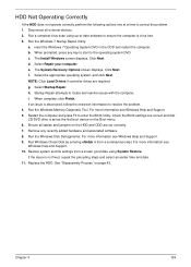
... dim at the highest brightness setting, the LCD is experiencing HDD or ODD BIOS information loss, disconnect and reconnect the power and data cables between devices. Click and drag the Resolution slider to its highest level. Run the Windows Memory Diagnostic from the BIOS, the drive may reduce display brightness. If the computer is faulty and should be replaced. See the User Manual for instructions on page 42...
... dim at the highest brightness setting, the LCD is experiencing HDD or ODD BIOS information loss, disconnect and reconnect the power and data cables between devices. Click and drag the Resolution slider to its highest level. Run the Windows Memory Diagnostic from the BIOS, the drive may reduce display brightness. If the computer is faulty and should be replaced. See the User Manual for instructions on page 42...
Service Guide
Page 151
... software. 8. The Install Windows screen displays. The System Recovery Options screen displays. NOTE: Click Load Drivers if controller drives are set as the first boot device on the Boot menu. 6. Startup Repair attempts to enter the BIOS Utility. i. Ensure all external devices. 2. Run Windows Check Disk by entering chkdsk /r from a known good date using up-to-date software to resolve the problem. 4. Chapter 4 139 b. Select Repair your computer. f. For more information see Windows Help and Support. 10. For more information see Windows Help and Support...
... software. 8. The Install Windows screen displays. The System Recovery Options screen displays. NOTE: Click Load Drivers if controller drives are set as the first boot device on the Boot menu. 6. Startup Repair attempts to enter the BIOS Utility. i. Ensure all external devices. 2. Run Windows Check Disk by entering chkdsk /r from a known good date using up-to-date software to resolve the problem. 4. Chapter 4 139 b. Select Repair your computer. f. For more information see Windows Help and Support. 10. For more information see Windows Help and Support...
Service Guide
Page 154
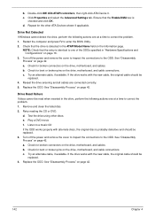
... to enter the BIOS Utility. 2. Turn off the power and remove the cover to inspect the connections to correct the problem. 1. a. Reseat the drive ensuring and all cables are connected correctly. 5. Drive Read Failure If discs cannot be replaced. 3. Retry reading the CD or DVD. Test the drive using other ATA Devices shown if applicable. e. Listen to a music CD If the ODD works properly with the new cable, the original cable should be...
... to enter the BIOS Utility. 2. Turn off the power and remove the cover to inspect the connections to correct the problem. 1. a. Reseat the drive ensuring and all cables are connected correctly. 5. Drive Read Failure If discs cannot be replaced. 3. Retry reading the CD or DVD. Test the drive using other ATA Devices shown if applicable. e. Listen to a music CD If the ODD works properly with the new cable, the original cable should be...
Service Guide
Page 156
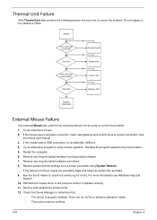
... date using System Restore. If the issue is a good connection. Roll back the mouse driver to verify mouse operation. Try an alternative mouse. 2. Remove any recently added software and reboot. 8. Remove any recently added hardware and associated software. 7. If the mouse uses a wireless connection, insert new batteries and confirm there is not fixed, repeat the preceding steps and select an earlier time and date. 9. Do not replace a non-defective FRUs: START Fan cable well connected? Try...
... date using System Restore. If the issue is a good connection. Roll back the mouse driver to verify mouse operation. Try an alternative mouse. 2. Remove any recently added software and reboot. 8. Remove any recently added hardware and associated software. 7. If the mouse uses a wireless connection, insert new batteries and confirm there is not fixed, repeat the preceding steps and select an earlier time and date. 9. Do not replace a non-defective FRUs: START Fan cable well connected? Try...
Service Guide
Page 245
...Board Removing 89 Replacing 101 Common Problems 132 computer on indicator 6 CPU 96 Replacing 97 Index D DIMM Modules Removing 52 Display 4 display hotkeys 14 E EasyTouch Failure 144 Euro 15 Express Dummy Card Removing 45 External Module Disassembly Flowchart 43 F Features 1 Finger Print Reader Removing 72 Replacing 108 Flash Utility 31 FRU (Field Replaceable Unit) List 167 H Hard Disk Drive Module Removing 50 HDD Removing 50 HDD Cover Removing 47 HDTV Switch Failure 144 Hibernation mode hotkey 14 Hinge Wells Removing 90 Replacing 101 Hot Keys 12 I Intermittent Problems 146 Internal Microphone...
...Board Removing 89 Replacing 101 Common Problems 132 computer on indicator 6 CPU 96 Replacing 97 Index D DIMM Modules Removing 52 Display 4 display hotkeys 14 E EasyTouch Failure 144 Euro 15 Express Dummy Card Removing 45 External Module Disassembly Flowchart 43 F Features 1 Finger Print Reader Removing 72 Replacing 108 Flash Utility 31 FRU (Field Replaceable Unit) List 167 H Hard Disk Drive Module Removing 50 HDD Removing 50 HDD Cover Removing 47 HDTV Switch Failure 144 Hibernation mode hotkey 14 Hinge Wells Removing 90 Replacing 101 Hot Keys 12 I Intermittent Problems 146 Internal Microphone...
Service Guide
Page 246
... K Keyboard Removing 57 Keyboard Failure 135 L Launch Board Removing 64 Replacing 117 LCD Failure 135 LCD Module Removing 77 Left Hinge Well Removing 90 Replacing 101 Left Saddle Removing 83 Replacing 104 Lower Cover Disassembly Flowchart 56 Lower Covers Removing 47 M Main Module Reassembly Procedure 97 Main Unit Disassembly Flowchart 55 Mainboard Removing 91 Replacing 100 media access on indicator 6 Media Board Removing 62 Replacing 119 Memory Check 132 Memory Cover Removing 47 MIC Board 234 Removing 71 Replacing 111 Model Definition 178 Modem Failure 143 MXM Card Removing...
... K Keyboard Removing 57 Keyboard Failure 135 L Launch Board Removing 64 Replacing 117 LCD Failure 135 LCD Module Removing 77 Left Hinge Well Removing 90 Replacing 101 Left Saddle Removing 83 Replacing 104 Lower Cover Disassembly Flowchart 56 Lower Covers Removing 47 M Main Module Reassembly Procedure 97 Main Unit Disassembly Flowchart 55 Mainboard Removing 91 Replacing 100 media access on indicator 6 Media Board Removing 62 Replacing 119 Memory Check 132 Memory Cover Removing 47 MIC Board 234 Removing 71 Replacing 111 Model Definition 178 Modem Failure 143 MXM Card Removing...


