Service Guide
Page 7
... System Block Diagram 6 UMA 6 Discrete (nVidia 7 Discrete (ATI 8 Your Acer Notebook tour 9 Top View 9 Rear view 10 Left View 11 Right View 12 Base view 13 Indicators 14 Touch Pad Basics 15 Using the Keyboard 16 Lock Keys and embedded numeric keypad 16 Windows Keys 17 Hot Keys...Navigating the BIOS Utility 31 Aspire 5742/5742G/5742Z/5742ZG BIOS 32 Information 32 Main 33 Security 34 Boot 37 Exit 38 BIOS Flash Utilities 39 DOS Flash Utility 40 WinFlash Utility 41 Remove HDD/BIOS Password Utilities 42 Machine Disassembly and Replacement 47 Disassembly Requirements 47 Pre...
... System Block Diagram 6 UMA 6 Discrete (nVidia 7 Discrete (ATI 8 Your Acer Notebook tour 9 Top View 9 Rear view 10 Left View 11 Right View 12 Base view 13 Indicators 14 Touch Pad Basics 15 Using the Keyboard 16 Lock Keys and embedded numeric keypad 16 Windows Keys 17 Hot Keys...Navigating the BIOS Utility 31 Aspire 5742/5742G/5742Z/5742ZG BIOS 32 Information 32 Main 33 Security 34 Boot 37 Exit 38 BIOS Flash Utilities 39 DOS Flash Utility 40 WinFlash Utility 41 Remove HDD/BIOS Password Utilities 42 Machine Disassembly and Replacement 47 Disassembly Requirements 47 Pre...
Service Guide
Page 8
... 140 Replacing the Speaker Module 141 Replacing the Upper Cover 142 Replacing the RTC Battery (UMA Only 146 Replacing the HDD Module 147 Replacing the WLAN Module 149 Replacing the DIMM Modules 151 Replacing the 3G Cover (Discrete Only 152 Replacing the Lower Logic Door 153 Replacing the ODD Module 154 Replacing the Keyboard 156 Replacing the SD Dummy Card 157 Replacing the...
... 140 Replacing the Speaker Module 141 Replacing the Upper Cover 142 Replacing the RTC Battery (UMA Only 146 Replacing the HDD Module 147 Replacing the WLAN Module 149 Replacing the DIMM Modules 151 Replacing the 3G Cover (Discrete Only 152 Replacing the Lower Logic Door 153 Replacing the ODD Module 154 Replacing the Keyboard 156 Replacing the SD Dummy Card 157 Replacing the...
Service Guide
Page 9
...159 Common Problems 159 Power On Issue 160 No Display Issue 161 Random Loss of BIOS Settings 162 LCD Failure 163 Internal Keyboard Failure 163 Touch Pad Failure 164 Internal Speaker Failure 164 Microphone Record Failure 166 USB Failure (Right side 167 HDD Not Operating... by Crisis Disk 197 FRU (Field Replaceable Unit) List 199 Aspire Exploded Diagrams 200 Main Assembly 200 Lower Cover 202 LCD Assembly 203 LED Assembly 204 Aspire FRU List 205 Screw List 229 Model Definition and Configuration 231 Aspire 5742/5742G 231 Aspire 5742Z/5742ZG 257 Test Compatible Components 273...
...159 Common Problems 159 Power On Issue 160 No Display Issue 161 Random Loss of BIOS Settings 162 LCD Failure 163 Internal Keyboard Failure 163 Touch Pad Failure 164 Internal Speaker Failure 164 Microphone Record Failure 166 USB Failure (Right side 167 HDD Not Operating... by Crisis Disk 197 FRU (Field Replaceable Unit) List 199 Aspire Exploded Diagrams 200 Main Assembly 200 Lower Cover 202 LCD Assembly 203 LED Assembly 204 Aspire FRU List 205 Screw List 229 Model Definition and Configuration 231 Aspire 5742/5742G 231 Aspire 5742Z/5742ZG 257 Test Compatible Components 273...
Service Guide
Page 59
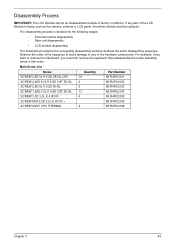
... the camera, antenna or LCD panel, the whole module must first remove the keyboard, then disassemble the inside assembly frame in the succeeding disassembly sections illustrate the entire disassembly sequence. Disassembly Process IMPORTANT: The LCD Module cannot be replaced. If any of factory conditions. For example, if you must be disassembled outside...
... the camera, antenna or LCD panel, the whole module must first remove the keyboard, then disassemble the inside assembly frame in the succeeding disassembly sections illustrate the entire disassembly sequence. Disassembly Process IMPORTANT: The LCD Module cannot be replaced. If any of factory conditions. For example, if you must be disassembled outside...

Service Guide
Page 166
Place the keyboard face down firmly to secure the cable in place. 3. Connect the keyboard FFC to the mainboard and close the locking latch to lock. 156 Chapter 3 Press down on the palm rest. 2. Replacing the Keyboard 1. Replace the keyboard by first lining up the bottom edge.
Place the keyboard face down firmly to secure the cable in place. 3. Connect the keyboard FFC to the mainboard and close the locking latch to lock. 156 Chapter 3 Press down on the palm rest. 2. Replacing the Keyboard 1. Replace the keyboard by first lining up the bottom edge.
Service Guide
Page 173
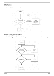
Do not replace a nondefective FRU: Internal Keyboard Failure If the built-in Keyboard fails, perform the following actions one at a time to correct the problem. Do not replace a non-defective FRU: Chapter 4 163 LCD Failure If the LCD fails, perform the following actions one at a time to correct the problem.
Do not replace a nondefective FRU: Internal Keyboard Failure If the built-in Keyboard fails, perform the following actions one at a time to correct the problem. Do not replace a non-defective FRU: Chapter 4 163 LCD Failure If the LCD fails, perform the following actions one at a time to correct the problem.


