Quick Start Guide
Page 5
...mentioned below will run the Adobe Reader setup program first. Follow the instructions on how to use your Acer notebook, we have designed a set of your computer. The Aspire Series Generic User Guide contains useful information applying to functions or features which are marked in Portable Document Format... you to the basic features and functions of guides: First off, the poster helps you get started with language such as using the keyboard and audio, etc. It covers basic topics such as "only for certain models". For more productive, please refer to the AcerSystem User...
...mentioned below will run the Adobe Reader setup program first. Follow the instructions on how to use your Acer notebook, we have designed a set of your computer. The Aspire Series Generic User Guide contains useful information applying to functions or features which are marked in Portable Document Format... you to the basic features and functions of guides: First off, the poster helps you get started with language such as using the keyboard and audio, etc. It covers basic topics such as "only for certain models". For more productive, please refer to the AcerSystem User...
Quick Start Guide
Page 7
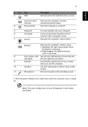
.... 1. The front panel indicators are visible even when the computer cover is closed up. Note: The exact configuration of your PC depends on and off. 5 Keyboard For entering data into your hands when you use the computer. 10 Speakers Left and right speakers deliver stereo audio output. 11 Microphone Internal microphone...
.... 1. The front panel indicators are visible even when the computer cover is closed up. Note: The exact configuration of your PC depends on and off. 5 Keyboard For entering data into your hands when you use the computer. 10 Speakers Left and right speakers deliver stereo audio output. 11 Microphone Internal microphone...
Service Guide
Page 7
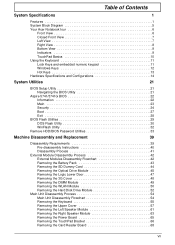
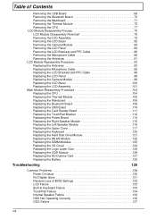
...Acer Notebook tour 6 Front View 6 Closed Front View 7 Left View 7 Right View 8 Bottom View 9 Indicators 9 TouchPad Basics 10 Using the Keyboard 11 Lock Keys and embedded numeric keypad 11 Windows Keys 12 Hot Keys 13 Hardware Specifications and Configurations 14 System Utilities 21 BIOS Setup Utility 21 Navigating the BIOS Utility 21 Aspire 5741... the Hard Disk Drive Module 52 Main Unit Disassembly Process 54 Main Unit Disassembly Flowchart 54 Removing the Keyboard 55 Removing the Upper Cover 57 Removing the Left Speaker Module 61 Removing the Right Speaker Module 63 ...
...Acer Notebook tour 6 Front View 6 Closed Front View 7 Left View 7 Right View 8 Bottom View 9 Indicators 9 TouchPad Basics 10 Using the Keyboard 11 Lock Keys and embedded numeric keypad 11 Windows Keys 12 Hot Keys 13 Hardware Specifications and Configurations 14 System Utilities 21 BIOS Setup Utility 21 Navigating the BIOS Utility 21 Aspire 5741... the Hard Disk Drive Module 52 Main Unit Disassembly Process 54 Main Unit Disassembly Flowchart 54 Removing the Keyboard 55 Removing the Upper Cover 57 Removing the Left Speaker Module 61 Removing the Right Speaker Module 63 ...
Service Guide
Page 8
... 112 Replacing the Power Board 114 Replacing the Right Speaker Module 115 Replacing the Left Speaker Module 116 Replacing the Upper Cover 117 Replacing the Keyboard 120 Replacing the Hard Disk Drive Module 121 Replacing the WLAN Module 122 Replacing the DIMM Modules 123 Replacing the 3G Cover 124 Replacing the...128 Troubleshooting 129 Common Problems 129 Power On Issue 130 No Display Issue 131 Random Loss of BIOS Settings 132 LCD Failure 133 Built-In Keyboard Failure 133 TouchPad Failure 134 Internal Speaker Failure 134 HDD Not Operating Correctly 136 ODD Failure 137 VIII
... 112 Replacing the Power Board 114 Replacing the Right Speaker Module 115 Replacing the Left Speaker Module 116 Replacing the Upper Cover 117 Replacing the Keyboard 120 Replacing the Hard Disk Drive Module 121 Replacing the WLAN Module 122 Replacing the DIMM Modules 123 Replacing the 3G Cover 124 Replacing the...128 Troubleshooting 129 Common Problems 129 Power On Issue 130 No Display Issue 131 Random Loss of BIOS Settings 132 LCD Failure 133 Built-In Keyboard Failure 133 TouchPad Failure 134 Internal Speaker Failure 134 HDD Not Operating Correctly 136 ODD Failure 137 VIII
Service Guide
Page 13
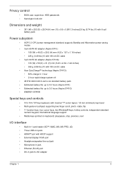
...Acer QuicCharge™ technology (Aspire 5741G): • 80% charge in 1 hour· • 2-hour rapid charge system-off • 48.8 W 4400 mAh 6-cell Li-ion standard battery pack • Estimated battery life: up to 4.0 hours (Aspire 5741) • Estimated battery life: up to 3.0 hours (Aspire... 5741G) • ENERGY STAR® Special keys and controls • 103-/104-/107-key keyboard, with inverted "T" cursor layout, 1.8 mm (minimum) key travel &#...
...Acer QuicCharge™ technology (Aspire 5741G): • 80% charge in 1 hour· • 2-hour rapid charge system-off • 48.8 W 4400 mAh 6-cell Li-ion standard battery pack • Estimated battery life: up to 4.0 hours (Aspire 5741) • Estimated battery life: up to 3.0 hours (Aspire... 5741G) • ENERGY STAR® Special keys and controls • 103-/104-/107-key keyboard, with inverted "T" cursor layout, 1.8 mm (minimum) key travel &#...
Service Guide
Page 16
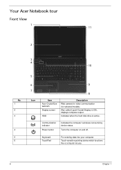
...device which functions like a computer mouse. 6 Chapter 1 Keyboard TouchPad For entering data into your computer. Communication indicator Power button Indicates the computer's wireless connectivitoy device status. Also called Liquid-Crystal Display (LCD), displays computer output. Your Acer Notebook tour Front View 1 11 2 No. 1 ...2 3 4 5 6 3 4 10 5 6 7 Icon 9 8 Item Acer Crystal Eye webcam Display screen HDD Description Web camera for video ...
...device which functions like a computer mouse. 6 Chapter 1 Keyboard TouchPad For entering data into your computer. Communication indicator Power button Indicates the computer's wireless connectivitoy device status. Also called Liquid-Crystal Display (LCD), displays computer output. Your Acer Notebook tour Front View 1 11 2 No. 1 ...2 3 4 5 6 3 4 10 5 6 7 Icon 9 8 Item Acer Crystal Eye webcam Display screen HDD Description Web camera for video ...

Service Guide
Page 21
Lock Keys and embedded numeric keypad The keyboard has two lock keys which you can toggle on , the contents of a text window scroll without moving the cursor. When Scroll Lock is on , the embedded keypad is in uppercase. When Num Lock is on , all alphabetic characters typed are in numeric mode. Chapter 1 11 Using the Keyboard The keyboard has full-sized keys and an embedded numeric keypad, separate cursor, lock, Windows, function and special keys. Lock key Caps Lock Scroll Lock Num Lock Description When Caps Lock is on and off.
Lock Keys and embedded numeric keypad The keyboard has two lock keys which you can toggle on , the contents of a text window scroll without moving the cursor. When Scroll Lock is on , the embedded keypad is in uppercase. When Num Lock is on , all alphabetic characters typed are in numeric mode. Chapter 1 11 Using the Keyboard The keyboard has full-sized keys and an embedded numeric keypad, separate cursor, lock, Windows, function and special keys. Lock key Caps Lock Scroll Lock Num Lock Description When Caps Lock is on and off.

Service Guide
Page 22
... box < > + : Cycle through programs on the taskbar < > + : Open Ease of Windows 7, some shortcuts may not function as clicking the right mouse button; Windows Keys The keyboard has two keys that perform Windows-specific functions. it launches the Start menu.
... box < > + : Cycle through programs on the taskbar < > + : Open Ease of Windows 7, some shortcuts may not function as clicking the right mouse button; Windows Keys The keyboard has two keys that perform Windows-specific functions. it launches the Start menu.
Service Guide
Page 28
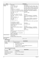
...; High Definition Audio Codec • Single Analogue MIC • 2.0 Watt speaker/5cc chamber/speaker size 18 phi, x2 • Headphone-out w/o SPDIF-out Power and Keyboard Controller Item Specification Controller Total number of keypads Windows logo key ENE KB926 99-/100-/103-key...
...; High Definition Audio Codec • Single Analogue MIC • 2.0 Watt speaker/5cc chamber/speaker size 18 phi, x2 • Headphone-out w/o SPDIF-out Power and Keyboard Controller Item Specification Controller Total number of keypads Windows logo key ENE KB926 99-/100-/103-key...
Service Guide
Page 51
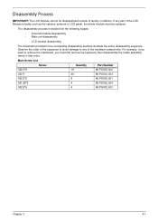
....5*6 4 86.PSV02.003 Chapter 3 41 The disassembly process is faulty, such as the camera, antenna or LCD panel, the whole module must first remove the keyboard, then disassemble the inside assembly frame in the succeeding disassembly sections illustrate the entire disassembly sequence. Disassembly Process IMPORTANT: The LCD Module cannot be replaced...
....5*6 4 86.PSV02.003 Chapter 3 41 The disassembly process is faulty, such as the camera, antenna or LCD panel, the whole module must first remove the keyboard, then disassemble the inside assembly frame in the succeeding disassembly sections illustrate the entire disassembly sequence. Disassembly Process IMPORTANT: The LCD Module cannot be replaced...
Service Guide
Page 52
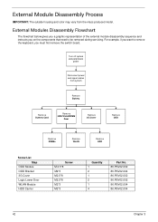
... Chapter 3 Turn off system and peripherals power Disconnect power and signal cables from the mass produced model. For example, if you want to remove the keyboard, you on the components that need to be removed during servicing. External Modules Disassembly Flowchart The flowchart below gives you a graphic representation of the external...
... Chapter 3 Turn off system and peripherals power Disconnect power and signal cables from the mass produced model. For example, if you want to remove the keyboard, you on the components that need to be removed during servicing. External Modules Disassembly Flowchart The flowchart below gives you a graphic representation of the external...
Service Guide
Page 64
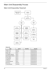
Main Unit Disassembly Process Main Unit Disassembly Flowchart Remove External Modules before proceeding Remove Keyboard Remove Upper Cover Upper Cover Lower Cover Remove Power Board Remove Left Speaker Module Remove Right Speaker Module Remove USB Board Remove TouchPad Bracket Remove ...
Main Unit Disassembly Process Main Unit Disassembly Flowchart Remove External Modules before proceeding Remove Keyboard Remove Upper Cover Upper Cover Lower Cover Remove Power Board Remove Left Speaker Module Remove Right Speaker Module Remove USB Board Remove TouchPad Bracket Remove ...
Service Guide
Page 65
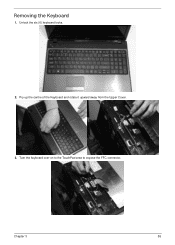
Turn the keyboard over on to the TouchPad area to expose the FFC connector. Unlock the six (6) keyboard locks. 2. Chapter 3 55 Pry up the centre of the Keyboard and rotate it upward away from the Upper Cover. 3. Removing the Keyboard 1.
Turn the keyboard over on to the TouchPad area to expose the FFC connector. Unlock the six (6) keyboard locks. 2. Chapter 3 55 Pry up the centre of the Keyboard and rotate it upward away from the Upper Cover. 3. Removing the Keyboard 1.

Service Guide
Page 66
Open the locking latch and disconnect the FFC from the mainboard. 5. 4. Lift the keyboard clear of the Upper Cover. 56 Chapter 3
Open the locking latch and disconnect the FFC from the mainboard. 5. 4. Lift the keyboard clear of the Upper Cover. 56 Chapter 3

Service Guide
Page 130
Connect the Keyboard FFC to the Mainboard and close the locking latch to lock. 120 Chapter 3 Press down firmly to secure the cable in place. 2. Replace the Keyboard by first lining up the bottom edge. Replacing the Keyboard 1.
Connect the Keyboard FFC to the Mainboard and close the locking latch to lock. 120 Chapter 3 Press down firmly to secure the cable in place. 2. Replace the Keyboard by first lining up the bottom edge. Replacing the Keyboard 1.
Service Guide
Page 139
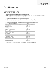
Non-Acer products, prototype cards, or modified options can give false errors and invalid system responses. 1. Use the following procedure as possible. 2. Symptoms (Verified) Go To Power On Issue Page 130 No Display Issue Page 131 LCD Failure Page 133 Internal Keyboard Failure Page 133 TouchPad ... Obtain the failing symptoms in as much detail as a guide for computer problems. NOTE: The diagnostic tests are intended to test only Acer products. Verify the symptoms by attempting to re-create the failure by running the diagnostic test or by repeating the same operation. 3. ...
Non-Acer products, prototype cards, or modified options can give false errors and invalid system responses. 1. Use the following procedure as possible. 2. Symptoms (Verified) Go To Power On Issue Page 130 No Display Issue Page 131 LCD Failure Page 133 Internal Keyboard Failure Page 133 TouchPad ... Obtain the failing symptoms in as much detail as a guide for computer problems. NOTE: The diagnostic tests are intended to test only Acer products. Verify the symptoms by attempting to re-create the failure by running the diagnostic test or by repeating the same operation. 3. ...
Service Guide
Page 143
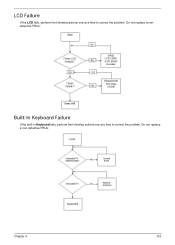
LCD Failure If the LCD fails, perform the following actions one at a time to correct the problem. Do not replace a non-defective FRUs: Chapter 4 133 Do not replace a nondefective FRUs: Built-In Keyboard Failure If the built-in Keyboard fails, perform the following actions one at a time to correct the problem.
LCD Failure If the LCD fails, perform the following actions one at a time to correct the problem. Do not replace a non-defective FRUs: Chapter 4 133 Do not replace a nondefective FRUs: Built-In Keyboard Failure If the built-in Keyboard fails, perform the following actions one at a time to correct the problem.

Service Guide
Page 156
... 2E 2F 30 31 32 33 34 Description Enter BDS entry Install Hotkey service ASF Initialization PCI enumeration PCI resource assign complete PCI enumeration complete Keyboard Controller, Keyboard and Mouse initialization Video device initialization Error report device initialization USB host controller initialization USB BUS driver initialization USB device driver initialization Console device...
... 2E 2F 30 31 32 33 34 Description Enter BDS entry Install Hotkey service ASF Initialization PCI enumeration PCI resource assign complete PCI enumeration complete Keyboard Controller, Keyboard and Mouse initialization Video device initialization Error report device initialization USB host controller initialization USB BUS driver initialization USB device driver initialization Console device...

Service Guide
Page 159
Jumper and Connector Locations Top View Chapter 5 Item JLVDS1 JSPK2 JSPK1 JKB1 JTP1 JUSB2 JCR1 Description Connect to LED / CCFL Connector Connect to Left Speaker Connect to Right Speaker Connect to Keyboard Connect to Touch pad (FFC) Connect to Power USB Board (FFC) Connect Card Reader Board (FFC) Item JLED1 JLED2 JP1 SW2/SW3 LED1/LED3 LED2/LED4 Description Connect to Powerboard (FFC) Connect to Powerboard (FFC) Connect to internal MIC Left button / Right button Power State Indicator Battery Charging Indicator Chapter 5 149
Jumper and Connector Locations Top View Chapter 5 Item JLVDS1 JSPK2 JSPK1 JKB1 JTP1 JUSB2 JCR1 Description Connect to LED / CCFL Connector Connect to Left Speaker Connect to Right Speaker Connect to Keyboard Connect to Touch pad (FFC) Connect to Power USB Board (FFC) Connect Card Reader Board (FFC) Item JLED1 JLED2 JP1 SW2/SW3 LED1/LED3 LED2/LED4 Description Connect to Powerboard (FFC) Connect to Powerboard (FFC) Connect to internal MIC Left button / Right button Power State Indicator Battery Charging Indicator Chapter 5 149
Service Guide
Page 166
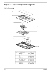
Aspire 5741/5741G Exploded Diagrams Main Assembly 1 2 3 6 7 4 5 8 No. Description 1 Keyboard 2 Upper Cover 3 CPU 4 USB Board 5 Card Reader Board 6 Thermal Module 7 Mainboard 8 Lower Cover Acer P/N KB.I170A.056 60.PSV02.001 KC.52001.DMP 55.PSV02.003 55.PSV02.002 60.PSV02.005 MB.PSV02.001 60.PSV02.002 156 Chapter 6
Aspire 5741/5741G Exploded Diagrams Main Assembly 1 2 3 6 7 4 5 8 No. Description 1 Keyboard 2 Upper Cover 3 CPU 4 USB Board 5 Card Reader Board 6 Thermal Module 7 Mainboard 8 Lower Cover Acer P/N KB.I170A.056 60.PSV02.001 KC.52001.DMP 55.PSV02.003 55.PSV02.002 60.PSV02.005 MB.PSV02.001 60.PSV02.002 156 Chapter 6


