
Acer Aspire 5534 Notebook Series Start Guide
Page 7
...'s battery pack. Note: Push to remove/install the card. Fully charged: The light shows blue when in -1 card reader Accepts Secure Digital (SD), MultiMediaCard (MMC), Memory Stick (MS), Memory Stick PRO (MS PRO), xDPicture Card (xD). Only one card can operate at any given time. 1.
...'s battery pack. Note: Push to remove/install the card. Fully charged: The light shows blue when in -1 card reader Accepts Secure Digital (SD), MultiMediaCard (MMC), Memory Stick (MS), Memory Stick PRO (MS PRO), xDPicture Card (xD). Only one card can operate at any given time. 1.
Acer Aspire 5534 Notebook Series Start Guide
Page 10
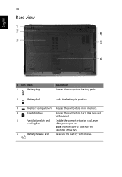
Note: Do not cover or obstruct the opening of the fan. 6 Battery release latch Releases the battery for removal. 10 Base view English # Icon Item 1 Battery bay Description Houses the computer's battery pack. 2 Battery lock Locks the battery in position. 3 Memory compartment Houses the computer's main memory. 4 Hard disk bay Houses the computer's hard disk (secured with screws). 5 Ventilation slots and Enable the computer to stay cool, even cooling fan after prolonged use.
Note: Do not cover or obstruct the opening of the fan. 6 Battery release latch Releases the battery for removal. 10 Base view English # Icon Item 1 Battery bay Description Houses the computer's battery pack. 2 Battery lock Locks the battery in position. 3 Memory compartment Houses the computer's main memory. 4 Hard disk bay Houses the computer's hard disk (secured with screws). 5 Ventilation slots and Enable the computer to stay cool, even cooling fan after prolonged use.
Acer Aspire 5534 Notebook Series Start Guide
Page 11
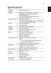
...; 64 X2 dual-core processor* AMD Athlon™ 64 single-core processor* AMD M780G Chipset Acer InviLink™ Nplify™ 802.11b/g/Draft-N* Acer InviLink™ 802.11b/g* Dual-channel support Up to 2 GB of DDR2 667 MHz memory, upgradeable to 4 GB using two soDIMM modules 15.6" HD 1366 x 768 16:9 aspect ratio...
...; 64 X2 dual-core processor* AMD Athlon™ 64 single-core processor* AMD M780G Chipset Acer InviLink™ Nplify™ 802.11b/g/Draft-N* Acer InviLink™ 802.11b/g* Dual-channel support Up to 2 GB of DDR2 667 MHz memory, upgradeable to 4 GB using two soDIMM modules 15.6" HD 1366 x 768 16:9 aspect ratio...

Aspire 5534 Service Guide
Page 5
...with all technical information relating to the BASIC CONFIGURATION decided for Acer's "global" product offering. For ACER-AUTHORIZED SERVICE PROVIDERS, your regional Acer office to -date information available on card, modem, or extra memory capability). This Service Guide provides you should check the most... have a DIFFERENT part number code to extend the functionality of a machine (e.g. You MUST use the list provided by your Acer office may have decided to those given in this printed Service Guide. To better fit local market requirements and enhance product competitiveness...
...with all technical information relating to the BASIC CONFIGURATION decided for Acer's "global" product offering. For ACER-AUTHORIZED SERVICE PROVIDERS, your regional Acer office to -date information available on card, modem, or extra memory capability). This Service Guide provides you should check the most... have a DIFFERENT part number code to extend the functionality of a machine (e.g. You MUST use the list provided by your Acer office may have decided to those given in this printed Service Guide. To better fit local market requirements and enhance product competitiveness...
Aspire 5534 Service Guide
Page 9
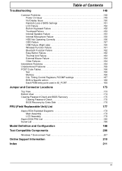
...Unit Failure 163 External Mouse Failure 164 Other Failures 164 Intermittent Problems 164 Undetermined Problems 165 POST Code Tables 166 Sec 166 Memory 166 DLL Timing Control Registers, RCOMP settings 167 BDS & Specific action 168 Each PEIM entry point used in 80_PORT 168 ...175 Clearing Password Check 175 BIOS Recovery by Crisis Disk 176 FRU (Field Replaceable Unit) List 177 Aspire 5534 Exploded Diagrams 178 Main Assembly 178 LCD Assembly 179 Aspire 5534 FRU List 180 Screw List 186 Model Definition and Configuration 188 Test Compatible Components 206 Windows 7 ...
...Unit Failure 163 External Mouse Failure 164 Other Failures 164 Intermittent Problems 164 Undetermined Problems 165 POST Code Tables 166 Sec 166 Memory 166 DLL Timing Control Registers, RCOMP settings 167 BDS & Specific action 168 Each PEIM entry point used in 80_PORT 168 ...175 Clearing Password Check 175 BIOS Recovery by Crisis Disk 176 FRU (Field Replaceable Unit) List 177 Aspire 5534 Exploded Diagrams 178 Main Assembly 178 LCD Assembly 179 Aspire 5534 FRU List 180 Screw List 186 Model Definition and Configuration 188 Test Compatible Components 206 Windows 7 ...

Aspire 5534 Service Guide
Page 11
...; AMD Athlon™ 64 single-core processor* • AMD M780G Chipset • Acer InviLink™ Nplify™ 802.11b/g/Draft-N* • Acer InviLink™ 802.11b/g* System Memory • Dual-channel support • Up to 2 GB of DDR2 667 MHz memory, upgradeable to 4 GB using two soDIMM modules Display and graphics • 15.6" HD... reader Audio subsystem • Two built-in stereo speakers • High-definition audio support • MS-Sound compatible • Built-in microphone Communication • Integrated Acer Crystal Eye webcam* • WLAN: Chapter 1 1
...; AMD Athlon™ 64 single-core processor* • AMD M780G Chipset • Acer InviLink™ Nplify™ 802.11b/g/Draft-N* • Acer InviLink™ 802.11b/g* System Memory • Dual-channel support • Up to 2 GB of DDR2 667 MHz memory, upgradeable to 4 GB using two soDIMM modules Display and graphics • 15.6" HD... reader Audio subsystem • Two built-in stereo speakers • High-definition audio support • MS-Sound compatible • Built-in microphone Communication • Integrated Acer Crystal Eye webcam* • WLAN: Chapter 1 1

Aspire 5534 Service Guide
Page 15
... time. HDD 10 Eject button 11 Speakers Closed Front View Indicates when the hard disk drive is charging. 2. Accepts Secure Digital (SD), MultiMediaCard (MMC), Memory Stick (MS), Memory Stick PRO (MS PRO), xDPicture Card (xD). No. 9 Icon Item Wireless LAN communication button/indicator Touchpad toggle Description Enables / disables the WLAN function. Chapter...
... time. HDD 10 Eject button 11 Speakers Closed Front View Indicates when the hard disk drive is charging. 2. Accepts Secure Digital (SD), MultiMediaCard (MMC), Memory Stick (MS), Memory Stick PRO (MS PRO), xDPicture Card (xD). No. 9 Icon Item Wireless LAN communication button/indicator Touchpad toggle Description Enables / disables the WLAN function. Chapter...

Aspire 5534 Service Guide
Page 17
... clip to the emergency eject hole to eject the optical drive tray when the computer is off . Memory compartment Hard Disk Bay Ventilation slots and/or cooling fan Battery Release Latch Houses the computer's main memory. Connects to an AC adapter. Enable the computer to USB 2.0 devices (e.g., USB mouse, USB camera). Connect...
... clip to the emergency eject hole to eject the optical drive tray when the computer is off . Memory compartment Hard Disk Bay Ventilation slots and/or cooling fan Battery Release Latch Houses the computer's main memory. Connects to an AC adapter. Enable the computer to USB 2.0 devices (e.g., USB mouse, USB camera). Connect...
Aspire 5534 Service Guide
Page 24
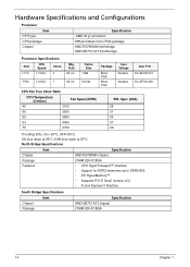
...AMD RS780MN chipset. Tech 65 nm TF20 1.6 GHz 1 65 nm Cache Size 1 MB 512 kB Package MicroPGA MicroPGA Core Voltage Variable Variable Acer P/N KC.AL002.310 KC.ATF02.200 CPU Fan True Value Table CPU Temperature (Celsius) Fan Speed (RPM) 45 3100 50 3500 55 ...Specification AMD S1g1 processor 638-pin lidless micro PGA package. Package 21MM 528-FCBGA Features • CPU HyperTransport™ Interface • Support for DDR2 memories up to DDR2-800 • ATI HyperMemory™ • Supports PCI-E Gen2 (version 2.0). • A-Link Express II Interface South Bridge ...
...AMD RS780MN chipset. Tech 65 nm TF20 1.6 GHz 1 65 nm Cache Size 1 MB 512 kB Package MicroPGA MicroPGA Core Voltage Variable Variable Acer P/N KC.AL002.310 KC.ATF02.200 CPU Fan True Value Table CPU Temperature (Celsius) Fan Speed (RPM) 45 3100 50 3500 55 ...Specification AMD S1g1 processor 638-pin lidless micro PGA package. Package 21MM 528-FCBGA Features • CPU HyperTransport™ Interface • Support for DDR2 memories up to DDR2-800 • ATI HyperMemory™ • Supports PCI-E Gen2 (version 2.0). • A-Link Express II Interface South Bridge ...

Aspire 5534 Service Guide
Page 25
Features Item System Memory Item Memory size DIMM socket number Supports memory size per socket Supports maximum memory size Supports DIMM type Supports DIMM Speed Video Specifications Item Chipset Package Features Specification • A-Link Express II interface • ...; Support for OpenGL® 2.0 • Motion Video Acceleration for HD DVD/Blu-ray technology • Adjustable 128MB UMA VGA memory share from North Bridge. • Adjustable 512MB DIS VGA memory share from North Bridge. • Max resoluiton 2048x1536 @85Hz (pixel clock at 388.5MHz) for 4:3 format, 2560x1440 @75Hz ...
Features Item System Memory Item Memory size DIMM socket number Supports memory size per socket Supports maximum memory size Supports DIMM type Supports DIMM Speed Video Specifications Item Chipset Package Features Specification • A-Link Express II interface • ...; Support for OpenGL® 2.0 • Motion Video Acceleration for HD DVD/Blu-ray technology • Adjustable 128MB UMA VGA memory share from North Bridge. • Adjustable 512MB DIS VGA memory share from North Bridge. • Max resoluiton 2048x1536 @85Hz (pixel clock at 388.5MHz) for 4:3 format, 2560x1440 @75Hz ...
Aspire 5534 Service Guide
Page 28
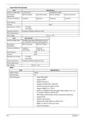
Super-Multi Drive Module Item Vendor & model name Performance Specification Transfer rate (MB/sec) Buffer Memory Interface Applicable disc formats Loading mechanism Power Requirement Input Voltage HLDS GU10N With CD Diskette Sustained: . Specification ...bezel SATA GBAS2.0 Performance Specification With CD Diskette With DVD Diskette Transfer rate (MB/sec) Sustained: 3,600 KB/sec Sustained: 10,800 KB/sec Buffer Memory 2 MB Interface SATA Applicable disc formats • • CD R/RW DVD R/RW Loading mechanism Emergency Release (draw open hole) Power Requirement Input Voltage...
Super-Multi Drive Module Item Vendor & model name Performance Specification Transfer rate (MB/sec) Buffer Memory Interface Applicable disc formats Loading mechanism Power Requirement Input Voltage HLDS GU10N With CD Diskette Sustained: . Specification ...bezel SATA GBAS2.0 Performance Specification With CD Diskette With DVD Diskette Transfer rate (MB/sec) Sustained: 3,600 KB/sec Sustained: 10,800 KB/sec Buffer Memory 2 MB Interface SATA Applicable disc formats • • CD R/RW DVD R/RW Loading mechanism Emergency Release (draw open hole) Power Requirement Input Voltage...
Aspire 5534 Service Guide
Page 35
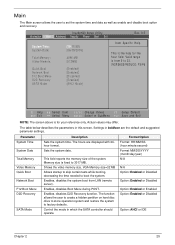
...Chapter 2 25 The table below describes the parameters in which the SATA controller should operate. Parameter System Time System Date Total Memory Video Memory Quick Boot Network Boot F12 Boot Menu D2D Recovery SATA Mode Description Sets the system time. The hours are the default and...of the system. Sets the system date. InsydeH20 Setup Utility Information Main Advanced Security Power Boot Exit Rev. 3.5 System Time: System Date: Total Memory: Video Memory: Quick Boot Network Boot F12 Boot Menu D2D Recovery SATA Mode [19:10:59] [06/09/2009] 4096 MB [512MB] [Enabled] [...
...Chapter 2 25 The table below describes the parameters in which the SATA controller should operate. Parameter System Time System Date Total Memory Video Memory Quick Boot Network Boot F12 Boot Menu D2D Recovery SATA Mode Description Sets the system time. The hours are the default and...of the system. Sets the system date. InsydeH20 Setup Utility Information Main Advanced Security Power Boot Exit Rev. 3.5 System Time: System Date: Total Memory: Video Memory: Quick Boot Network Boot F12 Boot Menu D2D Recovery SATA Mode [19:10:59] [06/09/2009] 4096 MB [512MB] [Enabled] [...
Aspire 5534 Service Guide
Page 37
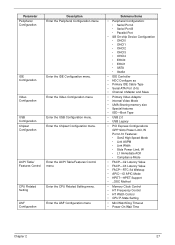
...IDE Cable Type • Serial ATA Port (0-5) • Channel 4 Master and Slave • Primary Video Adaptor • internal Video Mode • UMA Sharing memory size • Special features • IGD-Boot Type • USB 2.0 • USB Legacy • PCI Express Configurations GPP Slots Power Limit, W Port... FACP-C3 Latency Value • FACP-RTC S4 Wakeup • APIC-IO APIC Mode • HPET-HPET Support • _OSC Method • Memory Clock Control • HT Frequency Control • HT Width Control • CPU P-State Setting • Mini WatchDog Timeout • Power-On Wait...
...IDE Cable Type • Serial ATA Port (0-5) • Channel 4 Master and Slave • Primary Video Adaptor • internal Video Mode • UMA Sharing memory size • Special features • IGD-Boot Type • USB 2.0 • USB Legacy • PCI Express Configurations GPP Slots Power Limit, W Port... FACP-C3 Latency Value • FACP-RTC S4 Wakeup • APIC-IO APIC Mode • HPET-HPET Support • _OSC Method • Memory Clock Control • HT Frequency Control • HT Width Control • CPU P-State Setting • Mini WatchDog Timeout • Power-On Wait...

Aspire 5534 Service Guide
Page 44
BIOS Flash Utility The BIOS flash memory update is required for the following conditions: • New versions of system programs • New features or options • Restore a BIOS when it becomes corrupted. 34 Chapter 2
BIOS Flash Utility The BIOS flash memory update is required for the following conditions: • New versions of system programs • New features or options • Restore a BIOS when it becomes corrupted. 34 Chapter 2
Aspire 5534 Service Guide
Page 50
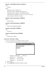
... editor, for example Notepad, to eeprom: 1. Example 1: Read DMI Information from Memory Input: dmitools /r Output: Manufacturer (Type1, Offset04h): Acer Product Name (Type1, Offset05h): Aspire 5534 xxxxx Serial Number (Type1, Offset07h): 01234567890123456789 UUID String (Type1, Offset08h): xxxxxxxx-xxxx-xxxx-xxxx-xxxxxxxxxxxx Asset Tag (Type3, Offset04h): Acer Asstag Example 2: Write Product Name to EEPROM Input: dmitools /wp...
... editor, for example Notepad, to eeprom: 1. Example 1: Read DMI Information from Memory Input: dmitools /r Output: Manufacturer (Type1, Offset04h): Acer Product Name (Type1, Offset05h): Aspire 5534 xxxxx Serial Number (Type1, Offset07h): 01234567890123456789 UUID String (Type1, Offset08h): xxxxxxxx-xxxx-xxxx-xxxx-xxxxxxxxxxxx Asset Tag (Type3, Offset04h): Acer Asstag Example 2: Write Product Name to EEPROM Input: dmitools /wp...

Aspire 5534 Service Guide
Page 63
... the thumb tab (indicated by the circle below shows the locations of SODIMM socket 1 to release the seven clips securing the cover in the Memory Cover. 3. Identify the SODIMM to remove. Push out the release latches on page 46 2. Removing the DIMM Module 1. Slot 0 must be... populated first when installing or replacing defective memory. 01 5. The image below ) to release the memory module. Chapter 3 53 Loosen the two captive screws in place. 4. Pull up to remove. See "Removing the Battery Pack...
... the thumb tab (indicated by the circle below shows the locations of SODIMM socket 1 to release the seven clips securing the cover in the Memory Cover. 3. Identify the SODIMM to remove. Push out the release latches on page 46 2. Removing the DIMM Module 1. Slot 0 must be... populated first when installing or replacing defective memory. 01 5. The image below ) to release the memory module. Chapter 3 53 Loosen the two captive screws in place. 4. Pull up to remove. See "Removing the Battery Pack...

Aspire 5534 Service Guide
Page 149
Replacing the DIMM Modules 1. Slot 0 must be populated first when installing or replacing defective memory. 2. 3. IMPORTANT:Ensure that the cables are replaced. The image below shows the locations of SODIMM slot 0 and SODIMM slot 1. NOTE: Cable placement is White to the AUX terminal (right) and Black to prevent them from being pinched when the lower covers are tucked into Slot 0. 01 Chapter 3 139 Insert a DIMM into the chassis to the MAIN terminal (left). Connect the Antenna cables to replace. Identify the SODIMM to the WLAN Board.
Replacing the DIMM Modules 1. Slot 0 must be populated first when installing or replacing defective memory. 2. 3. IMPORTANT:Ensure that the cables are replaced. The image below shows the locations of SODIMM slot 0 and SODIMM slot 1. NOTE: Cable placement is White to the AUX terminal (right) and Black to prevent them from being pinched when the lower covers are tucked into Slot 0. 01 Chapter 3 139 Insert a DIMM into the chassis to the MAIN terminal (left). Connect the Antenna cables to replace. Identify the SODIMM to the WLAN Board.

Aspire 5534 Service Guide
Page 155
Chapter 3 145 Place the HDD cover over the HDD bay. Press until the six tabs in the HDD Cover. 3. Replacing the Lower Covers 1. Place the Memory Cover on the memory bay. Tighten the two captive screws in the door engage. 2.
Chapter 3 145 Place the HDD cover over the HDD bay. Press until the six tabs in the HDD Cover. 3. Replacing the Lower Covers 1. Place the Memory Cover on the memory bay. Tighten the two captive screws in the door engage. 2.

Aspire 5534 Service Guide
Page 156
Tighten the two captive screws in the cover snap into place. 5. Press down until the seven clips in the Memory Cover. 146 Chapter 3 4.
Tighten the two captive screws in the cover snap into place. 5. Press down until the seven clips in the Memory Cover. 146 Chapter 3 4.
Aspire 5534 Service Guide
Page 160
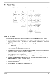
... on the external display, see "LCD Failure" on page 52). 8. Remove the drives (see "Disassembly Process" on page 152. 5. Drain any memory cards and CD/DVD discs. Reconnect the power and reboot the computer. 4. Remove any stored power by pressing Fn+F5. Restart the computer. Connect ...internal display is by pressing Fn+F5 (on page 191. Disconnect power and all external devices including port replicators or docking stations. Reseat the memory modules. 7. Do not replace a non-defective FRUs: No POST or Video If the POST or video doesn't display, perform the following ...
... on the external display, see "LCD Failure" on page 52). 8. Remove the drives (see "Disassembly Process" on page 152. 5. Drain any memory cards and CD/DVD discs. Reconnect the power and reboot the computer. 4. Remove any stored power by pressing Fn+F5. Restart the computer. Connect ...internal display is by pressing Fn+F5 (on page 191. Disconnect power and all external devices including port replicators or docking stations. Reseat the memory modules. 7. Do not replace a non-defective FRUs: No POST or Video If the POST or video doesn't display, perform the following ...


