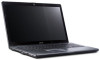
Acer Aspire 5534 Notebook Series Start Guide
Page 5
... Left and right speakers deliver stereo audio output. 5 English # Icon Item 2 Microphone Description Internal microphone for sound recording. 3 Display screen Also called Liquid-Crystal Display (LCD), displays computer output (Configuration may vary by models). 4 Power button / Turns the computer on and off . / indicator Indicates the computer's power status. 5 Keyboard For entering...
Acer Aspire 5534 Notebook Series Start Guide
Page 8
... stay cool, even after prolonged use. Connects to USB 2.0 devices (e.g., USB mouse, USB camera). USB 2.0 port Microphone-in jack Connect to a display device (e.g., external monitor, LCD projector). Accepts inputs from external microphones. 8 Left view English # Icon 1 2 3 4 5 Item Kensington lock slot Ventilation slots External display (VGA) port Description Connects to audio line...
Aspire 5534 Service Guide
Page 8
... the Thermal Module 88 Removing the CPU 89 LCD Module Disassembly Process 90 LCD Module Disassembly Flowchart 90 Removing the LCD Bezel 91 Removing the Camera Board 94 Removing the LCD Panel 95 Removing the FPC Cable 96 Removing the LCD Brackets 98 Removing the Microphone 99 Removing the ...the Antennas 103 Replacing the Microphone 104 Replacing the LCD Brackets 105 Replacing the FPC Cable 107 Replacing the LCD Panel 108 Replacing the Camera Board 109 Replacing the LCD Bezel 109 Main Unit Reassembly Process 112 Replacing the LCD Module 112 Replacing the CPU 113 Replacing the ...
Aspire 5534 Service Guide
Page 9
... Contents Troubleshooting 148 Common Problems 148 Power On Issue 149 No Display Issue 150 Random Loss of BIOS Settings 151 LCD Failure 152 Built-In Keyboard Failure 152 Touchpad Failure 153 Internal Speaker Failure 153 Internal Microphone Failure 155 HDD Not...Recovery 175 Clearing Password Check 175 BIOS Recovery by Crisis Disk 176 FRU (Field Replaceable Unit) List 177 Aspire 5534 Exploded Diagrams 178 Main Assembly 178 LCD Assembly 179 Aspire 5534 FRU List 180 Screw List 186 Model Definition and Configuration 188 Test Compatible Components 206 Windows 7 Environment ...
Aspire 5534 Service Guide
Page 14
... an overview of the features and functions of the notebook. Front View No. 1 2 3 4 5 6 7 8 4 Icon Item Acer Crystal Eye Webcam Microphone Description Web camera for sound recording. The left and right) Palmrest Also called Liquid-Crystal Display (LCD), displays computer output. Turns the computer on and off while indicating the computer's power status...
Aspire 5534 Service Guide
Page 16
... and turn the key to audio line-out devices (e.g., speakers, headphones). Connects to USB 2.0 devices (e.g., USB mouse, USB camera). Connect to a display device (e.g., external monitor, LCD projector).
Aspire 5534 Service Guide
Page 29
Integrated on mainboard • Supports 10/100/1000 mbps Specification ENE KB926 D3 Keyboard Controller 103/104/107 Yes Yes Chapter 1 19 LCD 15.6" Item Vendor/model name Screen Diagonal (mm.) Display Area (mm) Display resolution (pixels) Pixel Pitch (mm) Typical White Luminance (cd/ m2) also called Brightness ...
Aspire 5534 Service Guide
Page 54
... pack. Disassembly Process The disassembly process is divided into the following sections: q External components disassembly q Main unit disassembly q LCD module disassembly The flowcharts provided in that you must first remove the Keyboard, and LCD Module then disassemble the inside assembly frame in the succeeding disassembly sections illustrate the entire disassembly sequence. Observe...
Aspire 5534 Service Guide
Page 68
... Keyboard Remove Upper Cover Upper Cover Remove Function Board Lower Cover Remove Right Speaker Module Remove Left Speaker Module Remove I/O Board Remove Power Socket Remove LCD Module Remove CPU Fan Remove Power Board Remove Mainboard Remove Thermal Module Screw List Step Upper Cover Upper Cover Button Board TouchPad Bracket Power Board...
Aspire 5534 Service Guide
Page 69
Step I/O Board Mainboard Mainboard (Fan) LCD Module Fan Thermal Module Screw M2.5*6 M2.5*6 M2.5*6 M2.5*6 M2.5*6 M2.5*6 (spring tension) Quantity 1 1 1 3 1 4 Part No. 86.PEA02.007 86.PEA02.007 86.PEA02.007 86.PEA02.007 86.PEA02.007 86.PEA02.004 Chapter 3 59
Aspire 5534 Service Guide
Page 94
Removing the LCD Module 1. Remove the Microphone cable from the cable channel on page 81. 2. Lift the adhesive strip securing the WLAN cables in the cable channel 4. Remove the sponge securing the cables in place. 3. Remove the Antenna cables from the securing clips as shown, all the way to the hinge well. 5. See "Removing the Mainboard" on the Lower Cover as shown. 84 Chapter 3
Aspire 5534 Service Guide
Page 95
Remove the three screws on the rear of the Lower Cover securing the LCD Module to the Lower Cover. Using both hands, lift the LCD Module away from all cable clips before removing the LCD Module. 7. 6. Step LCD Module Size M2.5*6 Quantity 3 Screw Type IMPORTANT: Ensure that the LCD cables are free from the Lower Cover. Chapter 3 85
Aspire 5534 Service Guide
Page 100
... from Main Unit before proceeding Remove LCD Bezel Remove LCD Panel Remove Camera Module Remove LCD Brackets Remove LCD FPC Cable Remove Antennas Remove Microphone Screw List Step LCD Bezel LCD Panel Screw M2.5*4 M2*3 Quantity 4 4 Part No. 86.PEA02.003 86.PEA02.002 90 Chapter 3 During the removal and replacement ...are replaced in the disassembly procedures may not represent the actual model. NOTE: The product previews seen in the same position. LCD Module Disassembly Process IMPORTANT: Cable paths and positioning may not represent the final product color or configuration.
Aspire 5534 Service Guide
Page 101
Starting from the inside top edge, pry the bezel away from the LCD Module. Release the bottom edge of the bezel. 4. Chapter 3 91 Step LCD Bezel Size M2.5*4 Quantity 4 Screw Type p 3. Removing the LCD Bezel 1. See "Removing the LCD Module" on page 84. 2. Remove the four screw covers and four screws securing the front bezel to release the corners of the bezel, separating the securing clips. Continue moving along the top, prying the bezel away from the panel. If necessary, use a plastic pry to the LCD cover.
Aspire 5534 Service Guide
Page 102
Pry apart the hinge covers as shown. 6. Lift up the bezel and remove it from the LCD Module. 92 Chapter 3 5. Release the bottom edges of the LCD Module. 7.
Aspire 5534 Service Guide
Page 104
Disconnect the cable from the LCD Module. 3. Removing the Camera Board 1. Remove the Camera Board from the Camera Board as shown. 94 Chapter 3 See "Removing the LCD Bezel" on page 91. 2.
Aspire 5534 Service Guide
Page 105
on page 92. 2. Remove the four screws securing the LCD Panel to the LCD Module. Screw Type Chapter 3 95 See "Lift up the bezel and remove it from the LCD Module." Step LCD Panel M2*3 Size Quantity 4 3. Lift the LCD Panel out of the LCD Module front edge first. Removing the LCD Panel 1.
Aspire 5534 Service Guide
Page 106
Carefully lift the adhesive tape securing the LVDS cable connector to the LCD Panel. 4. Removing the FPC Cable 1. Hold the adhesive tape clear of the LCD Panel. 96 Chapter 3 Turn the LCD panel over on page 95. 2. Lift the camera cable to detach the adhesive securing the cable to the LCD Panel. 5. See "Removing the LCD Panel" on a clean surface. 3.
Aspire 5534 Service Guide
Page 107
6. Chapter 3 97 Disconnect the LCD cable as shown and remove the cable from the LCD Panel.
Aspire 5534 Service Guide
Page 108
Pick up and slide out from under the antenna cable. 98 Chapter 3 Lift the top of the left LCD Bracket up and slide out from under the antenna cable. 4. See "Removing the LCD Panel" on page 95. 2. Lift the top of the right LCD Bracket up the antenna cable so the bracket can clear the cable. 3. Removing the LCD Brackets 1.